Exploring Automotive Networks and ECUs in the World of SOME/IP
In the realm of automotive networks, Electronic Control Units (ECUs) play a vital role in managing various aspects of a vehicle's systems. Modern ECUs are sophisticated with Systems on Chip (SoCs) containing CPUs, memory, I/O ports, and communication interfaces. With examples of different types of ECUs in modern cars and the evolution towards more advanced functionalities like keyless entry and V2X communication, the automotive industry is constantly innovating to enhance vehicle performance and safety.

Download Presentation

Please find below an Image/Link to download the presentation.
The content on the website is provided AS IS for your information and personal use only. It may not be sold, licensed, or shared on other websites without obtaining consent from the author. Download presentation by click this link. If you encounter any issues during the download, it is possible that the publisher has removed the file from their server.
E N D
Presentation Transcript
Automotive networks and the world of SOME/IP Yaakov (J) Stein
ECUs An Electronic Control Unit (ECU) is exactly what you would imagine an electronic unit for controlling a (mechanical/electrical) system The term is mostly used in automotive systems where it can be confused with a specific ECU - the Engine Control Unit What exactly does an ECU do? input one or more (sensor) indications from the controlled system perform some calculation (all modern ECUs contain a CPU!) output one or more signals (actuations) to alter the operation of the controlled system ECU sensor actuator controlled system Y(J)S SOME/IP 2
Whats an ECU made of? Modern ECUs are SoCs (Systems on Chip) usually containing: CPU (8/16/32-bit, 10-100 MHz) flash memory for the software ( 1 MB) RAM for data (not always) signal conditioners, A/Ds, D/As, relays, etc. I/O ports (e.g., for diagnostics) communications interfaces (most of this talk!) Most ECUs today are specific to the car manufacturer and even to a model Y(J)S SOME/IP 3
For example? Modern cars can have between 10 and 100 ECUs, for example: Engine Control Unit (ECU) (fuel injection, air/fuel ratio, ignition timing, temp. correction, ) Transmission Control Unit* (automatic gear) Power Steering Controller Battery Management System Windshield Wiper Controller Speed Control Unit (cruise control) Brake Control Unit (ABS, anti-skidding) Turn Signal Control Module (blinkers) Air bags Tire pressure Light Control Module (headlights, rear lights, cabin lights) Body Control Unit(s) (A/C, immobilizer, door/window/mirror control/ ) Advanced Driver Assistance System Multimedia system Parking video camera Y(J)S SOME/IP 4 * WARNING: TCU also used for Telematics Control Unit
Newer ECUs As cars become more sophisticated there are more ECUs keyless entry remote start all-passenger personal infotainment Automatic Vehicle Location (telelocation) radar/lidar distance measurement lane assist 360 degree parking assist traffic sign recognition pedestrian detection V2X (V2V, V2I, V2P, ) including over 5G Y(J)S SOME/IP 5
And more futuristic! Augmented Reality dashboards / steering wheels distance and identification overlaid over objects on the road dangers highlighted platooning V2V fully self-driving (autonomous) delivery vehicles photoelectric recharging of electric vehicles Y(J)S SOME/IP 6
Why not a single CPU? Why are there so many ECUs instead of a single Central Processing Unit? History automotive technology has developed over time so it was natural to add an independent local ECU for each new feature Real time there may be tight delay constraints between sensing and actuation using separate ECUs eliminates most process queuing delays Reliability When there are critical reliability requirements, modularization - avoids single point of system-wide failure makes it simpler to develop bug-free code and prove correctness Y(J)S SOME/IP 7
Communications Because it is composed of many ECUs the automobile itself is essentially a distributed multiprocessor (parallel) computation system Some of these ECUs are, and should remain, completely independent For example, it s a really bad idea to allow the multimedia controller to access the steering or braking systems! ( see https://www.youtube.com/watch?v=MK0SrxBC1xs ) But many ECU do need to exchange information, for example: Engine Control Unit and Transmission Control Unit (many interactions!) reverse/parking controller needs TCU trigger Body Control Unit needs to lock doors upon attaining some speed diagnostics and dashboard instrumentation need data from almost all systems Y(J)S SOME/IP 8
The original solution With the proliferation of ECUs and their communications requirements automotive manufacturers started connecting them up using dedicated point-to-point links (some analog some digital) each with its own proprietary protocol This solution does have several advantages only ECUs truly requiring communications are interconnected (compartmentalization is good for security!) single purpose protocols may be simpler to design (at least the 1st time!) but resulted in numerous problems tremendous number of cables ( O(N2) ) difficult to aggregate information for instrumentation and diagnosis R&D and maintenance complexity Y(J)S SOME/IP 9
The cost of networking ECUs Over time the complexity, cost, and weight of wiring harnesses has significantly increased to the point where they are non-negligible Old cars have under 100 wires, reaching about 50 meters in length while modern cars can have over 1000 wires exceeding 1 km in length In fact wiring up can comprise 50% of the manufacturing labor cost copper wiring can add 25 kg to car s weight There is thus a strong drive for upgrading conventional communications with modern more efficient networking solutions It has been estimated that cost reduction may be up to 75% Y(J)S SOME/IP 10
Automotive network standards Vendors, automotive industry groups, and standards organizations have come up with networking standards for ECU interconnection Controller Area Network bus (CAN bus) [ISO 11898-1 11898-6] Local Interconnect Network(LIN bus) FlexRay [ISO 17458-1 17458-5] Media Oriented Systems Transport (MOST bus) Time-Triggered Ethernet (TTTech) [SAE AS6802] Scalable service-Oriented Middleware over IP (SOME/IP) application specific e.g., K-line diagnostics, OBD-II diagnostics and emissions monitoring We ll discuss some of the most important of these Y(J)S SOME/IP 11
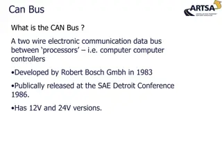
CAN bus Right now CAN bus is the dominant automotive ECU networking protocol nearly every automobile sold today has a CAN bus! Like many current ECU networking protocols the physical layer of CAN bus is a multi-master serial bus all ECUs are connected in parallel and all messages are broadcast the physical bus is balanced 2-wire (with termination resistors at bus ends) with differential voltage across these wires and NRZ encoding any ECU can transmit at any time all ECUs receive all messages, but only act on particular message IDs CAN nodes don t have L2 addresses (since topology is considered unimportant) but higher layers over CAN may support addressing Y(J)S SOME/IP 12
CAN bus history 1983 Bosch (German manufacturer) started development of CAN bus 1987 Intel produced the first CAN controller chips 1991 Mercedes Benz produced the first vehicle with CAN bus 1993 ISO released ISO 11898 for CAN bus, later divided into 11898-1 for layer 2 11898-2 for layer 1 at 1 Mbps 11898-3 for layer 1 at speeds up to 125 kbps 15765-2 for layers 3 and 4 1994 CAN bus became the de-facto L1/L2 standard in all US cars 2001 CAN bus became the de-facto L1/L2 standard for European cars Y(J)S SOME/IP 13
CAN speeds CAN buses are typically rated based on their speed Class A rating carries less than 10 Kbps for power windows, mirrors, seats, door locks, trunk releases, lights Class B rating from 10 Kbps up to 125 Kbps (SAE J1850 or ISO 9141-2) for instrumentation, transmission, security systems, climate control Class C speeds up to 1 megabits per second (many at 500 Kbps) for powertrain, ABS, stability control Class D is a proposal for speeds over 1 Mbps for onboard entertainment systems, video streaming Some vendors define proprietary classes based on 2 buses low and high speed GMLAN: low speed 33.33 Kbps and high speed 500 Kbps Mercedes: low speed 83 kbps and high speed 500 Kbps Y(J)S SOME/IP 14
CAN Multiple access method ECUs on a CAN bus may want to transmit at any time and so some Multiple Access mechanism must be provided CAN bus uses bit-wise deterministic collision avoidance the message with highest priority (lowest message ID) gains access and all other transmitters must stop and wait Note that the message ID is the first field in the message minimizing the arbitration time Strict priority based arbitration results in highest priority messages always transmitted with no delay lower priority messages preempted but transmitted afterwards straightforward analysis of latency for all messages Y(J)S SOME/IP 15
How are messages transmitted in CAN bus ? All CAN messages are broadcast to every ECU on the bus Every message starts with a single Start of Frame bit (0) and ends with End of Frame field (seven 1 bits) between messages there is a frame gap (at least three 1 bits) Bit stuffing is used if 7 consecutive 1s happened to appear in a message Messages contain: message type identifier (also used as priority indicator) all receivers observe and consume relevant messages message ID meanings are proprietary to manufacturers control bits and up to eight data bytes 15-bit CRC field for error detection (all single bit errors detected) Y(J)S SOME/IP 16
CAN frame types There are 4 kinds of CAN bus messages (frames) Data ECU broadcasts message to all other ECUs Remote sent to request data from a specific node Error transmitted by node detecting a bus error Overload (OBSOLETE) request more delay between data/remote frames Examples blinker ECU sends data frame with data indicating its state in order to turn on blinker lights turn on clicker sound and indicator on dashboard suppress lane departure warning central locking controller needs to know if the car is in park it sends a remote frame to TCU requesting park status TCU responds with data frame containing park status Y(J)S SOME/IP 17
Data frames (CAN 2.0 format) Just for concreteness, let s describe a CAN data frame (classic format) Start of Frame (1 bit) equals 0 Message ID (11 bits in base CAN, 29 bits in extended CAN) standard and extended frames may coexist, standard having higher priority Remote Transmission Request (1 bit) 0 in data frames, 1 in remote frames Reserved (2 bits) set to 0 Data Length Code (4 bits) number of data bytes 0 8) Data (0 8 bytes) serialized information, MSB sent first Cyclic Redundancy Check (15 bits) ACK (2 bits including Ack delimiter) indicates previous message passed CRC End of Frame (7 bits) all 1s Y(J)S SOME/IP 18
CAN serialization In serial protocols serialization is the process of formatting data into a sequence of bits deserialization is the recovery of data structures from the bit stream The CAN specification details its serialization functions, such as MSB is always transmitted first big-endian / little-endian for multibyte data is manufacturer dependent fields need not start on byte boundaries bit stuffing a maximum of 5 consecutive 0 or 1 bits is allowed if the data has >5 identical bits an additional opposite bit is inserted Y(J)S SOME/IP 19
CAN diagnostics CAN bus scanners are used by technicians to diagnose problems A CAN connector is located under the hood and/or under the dashboard The scanner receives and logs all CAN messages Another use is emissions conformance testing during annual test or when requested by authorities All modern cars have OnBoard Diagnosis IIusually based on CAN Y(J)S SOME/IP 20
Higher layers CAN defines L1 and L2, but leaves higher layers to other protocols, e.g. : ARINC CanKingdom CANopen CANopen Lift CCP/XCP DeviceNet EnergyBus ISO 11783 (ISOBUS) OSEK/VDX J1939 MilCAN Modbus NMEA 2000 SDS UAVCAN These protocols standardize message identifiers, set-up procedures, etc. Y(J)S SOME/IP 21
CANOpen As an example let s look a bit at CANOpen from CAN in Automation Every CANopen device implements CAN for L1 and L2 but for many message types the 11-bit CAN id is divided into 4-bit function code 7-bit CANopen NodeID (DA) Starting/resetting a device is controlled via a state machine with states : Initialization Pre-operational Operational Stopped Transitions between states are made by sending a Network ManagemenT object to the device Y(J)S SOME/IP 22
CANOpen device components Every CANOpen device must implement 1. an object dictionary (with standardized format) 2. an application part 3. a communication unit CANOpen uses variables for configuration and for measurement data variables are stored in the device s object dictionary (vector w/ 16 or 16+8 bit index) CANOpen functionsare implemented in each device s application part and only operate when the device is in operational state Communication object NMT (node control) Global failsafe command Sync protocol Emergency (error detected) TimeStamp Process Data Object Service Data Object heartbeat LSS Communication object ID (hex) 080 + NodeID 100 180/200/280/300/380/400/480/500 + NodeID 580/600 + NodeID 700 + NodeID 7E4, 7E5 The communication unit implements CAN and at least the IDs in this table 0 1 80 PDO: Input and output values (voltage, frequency, etc.) SDO: Configuration settings (node ID, baud rate, offset, etc.) Y(J)S SOME/IP 23
CANOpen operation Variables in an object dictionary are void, Boolean, (un)signed integer, float or char Every node implements a server that handles read/write from/to its object dictionary via CANOpen SDO messages CANOpen defines addresses / ranges in the dictionary for specific variables For example the master might write true to a variable to start a measurement and afterwards acquire the result by reading a float variable Process data (data that changes over time) is also stored in the object dictionary but the overhead of polling and receiving single responses would be excessive So data in the PDO segment of the object dictionary can be sent without being polled (event/time driven) via PDO messages In addition the CANopen master can get a system snapshot by sending a SYNC message to which multiple nodes respond Y(J)S SOME/IP 24
CANOpen modes in modern terms CANOpen implements a confusing mixture of operational modes NMT operates in master/slave mode where the master issues state machine change commands SDO operates in client/serverpull mode in which the client queries the server that replies with data PDO operates in push mode where an ECU sends information without polling Heartbeat protocol also operates in push mode to monitor verify nodes in the network are still alive Node guarding operates in a mixture of master/slave and pull mode monitoring the NMT state of a device Y(J)S SOME/IP 25
LIN bus LIN bus is a very different ECU bus protocol designed to be cheaperthan CAN bus uses a single wire instead of 2-wire lower reliability (but guaranteed latency) limited to 40 m of cabling very low data rates (19.2 kbps or 20 kbps, depending on variant) master-slave operation (single master node and up to 16 slaves) no node synchronization to save on expensive crystal oscillators LIN arrived after CAN (about 1998), and was developed by the LIN consortium (Audi, Volvo, VW, BMW, Mercedes) along with Volcano (Mentor Graphics) and Motorola (Freescale, NXP) LIN is commonly used today as a sub-bus for CAN and Flexray Y(J)S SOME/IP 26
LIN multiple access method LIN slave nodes have 7-bit addresses (NADs) composed of supplier ID + function ID + variant ID and NADs can be automatically assigned using Slave Node Position Detection All communication is initiated by the master sending to a single slave thus no collision avoidance is needed The LIN master node decides what is transmitted by maintaining a schedule table A slave only transmits after being invited to do so by the master however all nodes can read any data transmitted on the bus The master invites itself to transmit when it needs to broadcast data Y(J)S SOME/IP 27
LIN frames A LIN bus frame consist of Synchronization break ( 13 bits) Frame Alignment Sequence alternations Synchronization (1 byte) 0x55 (LSB sent first) Identifier byte (1 byte) message type = 6 ID bits + 2 parity check bits Data bytes (2, 4, or 8 bytes) Checksum byte The master transmits a header that consists of a break signal followed by synchronization and identifier fields. Slaves respond with a data frame that include 2, 4 or 8 data bytes plus 3 bytes of control information Y(J)S SOME/IP 28
LIN frames LIN defines multiple frame types since the ID is 6 bits, there can be only 64 frame types in a system Unconditional (ID=0 59) frames carry data and are sent to all nodes Sporadic (unconditional message triggered by value change, not periodic) Event-triggered like sporadic, but several slaves can respond with same ID Master request diagnostic (ID=60) Slave response diagnostic (ID=61) User-defined (ID=62) Reserved (ID=63) Y(J)S SOME/IP 29
FlexRay FlexRay was developed by the FlexRay Consortium (initially Freescale, Bosch, NXP, BMW, VW, Daimler, GM) At the end of 2009, the consortium disbanded but the FlexRay standard is now maintained by ISO FlexRay was designed to be better than CAN bus faster (10 Mbps) more deterministic (when needed) more fault tolerant but also much more expensive (aimed at luxury cars) The first FlexRay capable car was from BMW at the end of 2006 followed by Audi, Bentley, Mercedes, Lamborghini, Rolls-Royce, Volvo Many believe that FlexRay will be completely replaced by Ethernet Y(J)S SOME/IP 30
FlexRay wiring FlexRay networks may be single channel (2 wire) but are almost always dual channel (4 wire) for fault tolerance In addition to these 1 or 2 pairs of Unshielded Twisted Pair there are further ground and power wires FlexRay networks can either be buses (like CAN or LIN) or star topologies or hybrids (star(s) hanging off the bus) depending on requirements and cost Y(J)S SOME/IP 31
FlexRay multiple access method FlexRay enables Time Division Multiple Access for enhanced determinism similar to WiFi, Passive Optical Networks, and some 2G cellular systems All FlexRay nodes are synchronized to the same clock to within 10 sec and nodes only transmit during their allotted timeslots The cycle is constant for a given network and typically chosen between 1 and 5 millisecond This cycle is divided into 4 segments: Static Segment for time-triggered messages Dynamic Segment for event-triggered messages (CAN-like) Symbol Window for network startup and maintenance signaling Idle Time used to maintain sync between nodes SS DS SW IT Y(J)S SOME/IP 32
MOST MOST is an automotive shared bus network for multimedia There are variants at rates of 25, 50, 100, and 150 Mbps and it can run over multi-wire copper (MOST50, MOST150) or plastic optical fiber (MOST25, MOST100) The lowest rate (MOST25) already supports 15 channels of uncompressed CD-quality audio or compressed MP1 video+audio MOST was created by OASIS Silicon (acquired by SMSC) maintained since 1998 by the MOST Cooperation The first MOST capable vehicle was released in 2001 and today it is supported by many automotive manufacturers including almost all European ones (Audi, BMW, Mercedes-Benz, Volkswagen, Volvo, ) as well as GM, Honda, Toyota and Hyundai Y(J)S SOME/IP 33
MOST transport MOST defines all layers of the protocol stack At layer 1 MOST networks are synchronous (like TDM and SDH/SONET) differential Manchester coded logical ring ( 64 node) topology ring is actually N-1 point-to-point links with idle regeneration or add/drop at each node At layer 2 MOST25 has 64 byte frames MOST50 has 128 byte frames MOST100 has 256 byte frames MOST150 has 384 byte frames and each frame contains (in addition to preamble and header) control channel (2/4 bytes) for commands e.g., stop playing synchronous channel for real-time streaming data (video or audio) packet data channel for bulk/bursty data Y(J)S SOME/IP 34
MOST network operation Every MOST network has a timing master that periodically generates frames All are other nodes are timing slaves that: receive the frame synchronize with the preamble using a PLL parse the frame and decides if it needs to process it if no need to process: then the frame is forwarded as-is if processing needed: process control and/or data information add information in empty fields of the frame transmit the frame to the next node on the ring At the end the frame returns to the timing master Y(J)S SOME/IP 35
Higher layers MOST frames are aggregated into blocks MOST High Protocol maps to layers 3 and 4 MOST Async Medium Access Control adaptation layer can translate between MOST layer 2 and Ethernet and between MHP and TCP/IP At the application layer MOST devices are composed of function blocks which define the API for controlling the device (e.g., radio or MP3 player) and for network management (NetBlock - mandatory) Each function block has an XML descriptor The programming structure of MOST devices is also well defined but describing it would take us too far astray Y(J)S SOME/IP 36
Comparison so far speed MOST150 MOST100 MOST50 MOST25 100 Mbps 10 Mbps FlexRay 1 Mbps CAN-C 125 kbps CAN-B LIN 20 kbps 10 kbps CAN-A relative cost Y(J)S SOME/IP 37
Limitations There are already so many ECU networking protocols why would anyone need something new? Current protocols are limited in speed good enough for traditional uses capabilities hard to implement new paradigms such as a computational resource ECU interfaces basically each higher layer is locked to a L1 and L2 resulting in many different networks in each vehicle interoperability most protocols have significant manufacturer proprietary parts This has led people to consider the modern universal standards Ethernet for L1/L2 and the IP suite for L3+ Y(J)S SOME/IP 38
Why not Ethernet ? However, Ethernet has many drawbacks that may make it inapplicable Ethernet L1 was not designed for harsh environments (vibrations, acceleration, temperature) standard RJ45 connectors do not tolerate vibration, gold contacts corrode, etc. Ethernet copper L1 does not work well in noisy vehicle environments and may itself produce excessive EMI/RFI Ethernet cabling (e.g., CAT5 4 twisted pairs) is far too expensive Ethernet does not have native reliability guarantees Ethernet is asynchronous while many applications require synchronous operation Ethernet does not natively distribute synchronization Ethernet L2 can not guarantee latency in low sec (for steering, ECU, TCU) Ethernet flow bandwidth allocation is BE and not guaranteed Ethernet s popularity has resulted in multiple security issues Bus Ethernet is no longer supported (see next slide) Y(J)S SOME/IP 39
Bus vs. switched Ethernet Ethernet originated as a peer-peer bus, similar to automotive networks with coaxial cable as the physical medium and CSMA/CD as the multiple access mechanism But the bus physical topology was abandoned long ago (unavailable after 10 Mbps rate) in favor of switched Ethernet with a star topology Switched Ethernet employs dedicated point-to-point links from the switch to every node, and 2 nodes communicate via the switch This already adds several disadvantages it requires much more wiring and lengthens link lengths it adds an expensive switch to the network the switch is a single point of failure and a traffic bottleneck switch Y(J)S SOME/IP 40
TCP/IP/Eth may never completely replace CAN So there is the elephant in the room! CAN bus frames contain between 0 and 8 bytes (0-64 bits) of data to which base CAN adds 47 bits (extended CAN 67 bits) But TCP/IP/ETH adds 656 bits of overhead! (20B L1, 22B L2, 20B L3, 20B L4)* data(bytes) 0 1 2 3 4 5 6 7 8 So the bandwidth ratio TCP/IPv4 vs base TCP/IPv4 vs ext 13.96 9.79 12.07 8.85 10.67 8.10 9.58 7.47 8.71 6.95 8.00 6.50 7.41 6.12 6.91 5.79 6.49 5.50 With a 2 byte payload TCP/IP/Eth consumes > 10 times the bandwidth of base CAN! So TCP/IP/Eth should only be used for ECUs with large payloads and CAN is frequently still used for traditional ECUs Of course, since we are talking about switched Ethernet this bandwidth is not shared like in CAN bus but one could connect CAN devices point-to-point, but that is never done to save wiring! *Note: with IPv6 the header size is 20 bytes longer - 816 bits Y(J)S SOME/IP 41
What to do about it? As mentioned, many modern systems retain CAN (or similar) for services with short messages reserving the IP/Ethernet network for services with long messages SOME/IP has a built-in mechanism to concatenate messages into a single IP UDP/IP or TCP/IP packet at the cost of some added delay AUTOSAR s Socket Adapter (between the IP stack and the application) also has its own mechanism to concatenate messages TCP s Nagle algorithm combines small packets, but is disabled in SOME/IP The IP suite has standardized header compression mechanisms that reduce the TCP/IP headers to 3-4 bytes but these are not used in automotive systems Y(J)S SOME/IP 42
Ethernet-CAN gateways It may be desirable to access CAN devices from Ethernet, for example: accelerate firmware flashing of CAN devices access CAN logging/diagnostics from a PC enable communications between CAN and Ethernet ECUs enable remote (cellular) monitoring/actuation of CAN devices For this reason CAN-Ethernet gateways are presently available CAN GW OBD switch Ethernet Y(J)S SOME/IP 43
Industrial Ethernet Ethernet is such a popular technology that many of its disadvantages have been addressed in other contexts In particular, Industrial Ethernet provides : reliability HSR and PRP redundancy mechanisms harsh environments M8 and M12 rugged watertight connectors, extended temperature range switch standards low latency EtherCAT (IEC 6158) MAC reduces latency, AVB/TSN can give latency bounds But Industrial Ethernet is much more expensive than plain Ethernet which is already much more expensive than CAN Y(J)S SOME/IP 44
Broad-R Reach Broadcom created a new Ethernet 100 Mbps L1 called BroadR-Reach specifically for automotive networking uses a single UTP cable, maximum length of 15 m is full duplex over this single pair using echo cancellation DSP uses PAM3 code pairs to achieve 3 bits per symbol to reduce analog BW and thus reduces crosstalk and can meet automotive EMI/RFI specs uses a highly optimized scrambler to better de-correlate signals IEEE has standardized this as 100BASE-T1 (802.3bw, 802.3-2015 Clause 96) (the 1 stands for 1 pair, and this was followed by 1000Base-T1 802.3bp) In 2011 the OPEN (One-Pair EtherNet) Alliance was formed and Broadcom RAND licenses to all OPEN Alliance members (currently > 300 members) Y(J)S SOME/IP 45
What about timing and reliability? Ethernet has completely replaced all previous networking technologies (token ring, token bus, ATM, frame relay, ) in many applications but was never adopted for the most demanding environments such as industrial control systems, vehicle control, video distribution In particular, Ethernet could not meet ISO 26262 requirements for mission-critical vehicle systems like braking or steering This is because Ethernet is a asynchronous, Best Effort, technology Recently special flavors of Ethernet have been developed providing low delay high reliability to help Ethernet conquer these applications as well Y(J)S SOME/IP 46
TTTech Another proprietary solution is Time Triggered Ethernet (TTE) from TTTech TTE extends standard Ethernet for reliable time-critical applications In 2011 TTE was adopted by Society of Automotive Engineers as AS6802 and later adopted by NASA and ESA for some space communications TTE switches are Ethernet switches with accurate synchronization time-triggered flow control and traffic scheduling bandwidth partitioning Most of TTEs functionalities are now available in 802.1 standard Audio Video Bridging and Time Sensitive Networking Y(J)S SOME/IP 47
AVB During 2005-2012 the IEEE Audio Video Bridging Task Group addressed time-sensitive Ethernet, mostly for the home AV market AVB extends switched Ethernet to provide synchronization (timing over Ethernet frames) low-latency reliability The following standards were developed by the AVB TG 802.1BA Audio Video Bridging (AVB) Systems 802.1AS Timing and Synchronization for Time-Sensitive Applications 802.1Qav Forwarding and Queuing for Time-Sensitive Streams 802.1Qat Stream Reservation Protocol (Qav and Qat were absorbed into 802.1Q-2011) Y(J)S SOME/IP 48
TSN In 2012 the AVB TG was renamed TSN to handle additional use cases industrial, infrastructure, vehicular/transportation, fronthaul, etc. TSN fundamental principles: highly accurate synchronization of Ethernet switches (better than 1 sec) protocol for reservation of resources (buffers, BW on links) achieve bounded latency for time sensitive streams, using new time-based buffering/queuing mechanisms new frame preemption mechanism achieve very high availability and very low PLR zero congestion loss 1+1 replication + elimination mechanism co-existence of BE and TSN traffic (up to 75%) Y(J)S SOME/IP 49
Example TSN mechanism preemption 802.1Qbu frame preemption was adopted in 2016 and absorbed into 802.1Q When express frame(s) arrives and a normal frame is being transmitted the packet transmission of the normal frame is temporarily suspended the neighboring switch buffers the content received the express frame(s) are sent and forwarded the transmission of the normal frame is continued the neighboring switch reassembles the outgoing packet and forwards Optimal bandwidth utilization of background traffic for time aware shaping and low-latency communication in non-scheduled networks Y(J)S SOME/IP 50


")