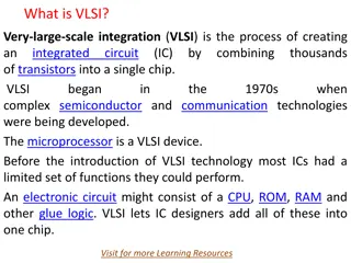
Comprehensive Overview of Fault Modeling and Fault Simulation in VLSI
Explore the intricacies of fault modeling and fault simulation in VLSI design, covering topics such as testing philosophy, role of testing in VLSI, technology trends affecting testing, fault types, fault equivalence, dominance, collapsing, and simulation methods. Understand the importance of testing and verification in the VLSI design flow, along with definitions of design synthesis, verification, and testing. Delve into the comparison between testing and verification and gain insights from analogies with class tests. Learn through examples and statistical analysis how testing processes are applied in different scenarios.

Download Presentation

Please find below an Image/Link to download the presentation.
The content on the website is provided AS IS for your information and personal use only. It may not be sold, licensed, or shared on other websites without obtaining consent from the author. Download presentation by click this link. If you encounter any issues during the download, it is possible that the publisher has removed the file from their server.
E N D
Presentation Transcript
Fault modeling and fault simulation (unit1) By Deepa,Asst.Professor SIT
contents Testing Philosophy Role of Testing Digital and Analog VLSI Testing VLSI Technology Trends Affecting Testing. Faults:Single Stuck at faults, Temporary Faults. Bridging faults, Transient faults. Fault modeling: Fault equivalence, dominance and collapsing. Fault Simulation: parallel, concurrent and deductive simulation.
Importance of Testing and verification in VLSI design flow
Definitions Design synthesis: Given an I/O function, develop a procedure to manufacture a device using known materials and processes. Verification: Predictive analysis to ensure that the synthesized design, when manufactured, will perform the given I/O function. Test: A manufacturing step that ensures that the physical device, manufactured from the synthesized design, has no manufacturing defect.
Comparison between Testing and Verification
Testing Philosophy Analogy with class test Theteacher sets a domain of knowledge for testing, called the course syllabus. The teacher asks questions and analyzes the response, perhaps by matching answers to correct ones from the book. The quality of such a test system depends upon how well the test questions cover the syllabus. you can do better by asking your teacher, right at the beginning, about (1) the course syllabus and (2) error models (i.e., what you will be tested for), and then plan your studies to succeed. In VLSI, that is called design for testability.
Example Testing of students. In a course on zeeology,70% of the studentsdeserve to pass. We will call them pass quality students. Assuming that the num-ber of students in the class is large, we will study the test process using a statistical basis. For a randomly selected student from the class, we define the following events: PQ: student is pass quality FQ: student is fail quality P: F: student passes the test student fails the test Figure : A pass/fail test.
The total probability of passing is, We will examine the conditional probability Prob(FQ\P) And,therefore: That is, 2.2% of passed students are of fail quality. We will call this the teacher s risk. Applying the Bayes rule, we obtain
Role of Testing If you design a product, fabricate and test it, and it fails the test, then there must be a cause for the failure. Either (1) the test was wrong, or (2) the fabrication process was faulty, or (3) the design was incorrect, or (4) the specification had a problem. Anything can go wrong. The role of testing is to detect whether something went wrong and the role of diagnosis is to determine exactly what went wrong, and where the process needs to be altered. Therefore, correctness and effectiveness of testing is most important for quality products (another name for perfect products.) The benefits of testing are quality and economy
Digital and Analog VLSI Testing There are two methods of testing 1. VLSI realization process (a naive version.): verification is not done in each and every step of VLSI design flow. Only testing of fabricated chip is done. Then yield may be very less. 2. A realistic VLSI realization process: cross verification is done in each and every step and corrective measures taken. The no. of faulty chips are less. Time and money is saved.
VLSI realization process (a naive version) Requirements are the user needs satisfied by the chip. One sets specifications of various types, which include function (input- output operating characteristics (power, frequency, noise, etc.), physical characteristics (packaging, etc.), environmental (tempera-ture, reliability, etc.), characteristics (volume, cost, price, avail-ability, etc.) down the characteristics), characteristics humidity, and other
The objective of design is to produce data necessary for the next steps of fabrication and testing. Design has several stages. The first, known as architectural design, logic design, a chip layout is produced during physical design. It is naive to think that every fabricated chip will be good. Impurities and defects in materials, equipment malfunctions, and human errors are some causes of defects
Failure Mode Analysis(FMA) Failure Mode Analysis (FMA): The faulty chip analysis is called failure mode analysis (FMA.) The arrows out of the FMA block represent the corrective actions applied to the faulty steps of the realization process. Disadvantages: 1. Time From the point of testing, where it was detected, is wasted. 2. Wasted effort and material adds to the product cost.
A realistic VLSI realization process Figure : A realistic VLSI realization process
Requirements: The process begins with a dialogue between the customer and the marketing engineer. Audit is done to ensure that requirements are realistic. As specifications are involvement of those responsible for later activities (design, manufacture, and test) is advisable to ensure realizable specification. The systems engineer constructing an architectural block diagram. The architecture is verified by high-level simulation and each block is synthesized at the logic-level. The logic circuit is simulated for the same prepared, some then begins by
The VLSI design engineer generates a layout and verifies the timing against the specification. Manufacturing and test engineers then fabricate and test wafers, and package and test chips. . Finally, the sales and field application en- gineers interact with the customer. Advantage:As verification and test related activities are distributed throughout the lifetime of the device, the design cost and time is saved. Yield will also be high
VLSI Technology Trends Affecting Testing Technology trends affecting Testing are 1. Rising Chip Clock Rates i. At-Speed Testing ii. Automatic Test Equipment(ATE) Cost iii. Electromagnetic Interference(EMI) 2. Increasing Transistor Density i. Test complexity ii. . Feature scaling and power dissipation iii. Current testing
Rising Chip Clock Rates The complexity of VLSI technology has reached the point where we are trying to increase the on- chip clock frequency to 1 GHz. These trends have a profound effect on the cost and difficulty of chip testing. i. At-Speed Testing:For a reliable high-speed test, the automatic test equipment (ATE) must operate as fast as, or faster than, the circuit- under-test (CUT.) Ex: if CUT has now upgraded from 1MHz to 1.6MHz then the new ATE must be bought with 1.6MHz.Then testing cost will increase which in turn increases product cost.
ATE Cost: a state of the art ATE can apply vectors at a clock rate of 1 GHz. The cost of such a tester rises roughly at the rate of $3,000 per pin. a fixed cost of function generators needed for mixed-signal circuits that can range between 0.5 1.2 million dollars Example : Testing cost. A state of the art ATE in the year 2000 appliestest vectors at clock rates up to 500 MHz. It contains analog instruments(function generators, A/D converters and waveform analyzers.) The price of this tester for a 1,024 pin configuration is estimated as
We compute the yearly running cost of the ATE by assuming a linear depreciation over five years, and an annual maintenance cost of 2% of the purchase price. The tester is used in three eight-hour shifts per day and on all days of the year. Therefore: The test time for a digital ASIC (application specific integrated circuit) is 6 seconds. That gives the test cost as 27 cents. Since the bad chips are not sold, their test cost must be recovered from the sale of good chips. If the yield is 65%, then the test component in the sale price of a good chip is 27/0.65=41.7 cents
Electromagnetic Interference(EMI) A chip operating in the GHz frequency range must be tested for EMI. This is a problem because inductance in thewiring becomes active at these higher frequencies. The inherent difficulties are: (1) Ringing in signal transitions along the wiring, because signal transitions are reflected from the ends of a bus and bounce back to the source, where they are reflected again (2) Interference with signal propagation through the wiring caused by the dielectricpermeability and the dielectric permittivity of the chip package (3) De-lay testing of paths requires propagation of sharp signal transitions, resulting in high-frequency currents through interconnects, causing radiation coupling.
Increasing Transistor Density Transistor feature sizes on a VLSI chip reduceroughly by 10.5% per year, resulting in a transistor density increase of roughly 22.1% every year. This amounts to little over doubling every two years. The doubling of transistors on an integrated circuit every 18 to 24 months has been known as Moore sLaw
Test complexity Testing difficulty increases as the transistor density increases. This occurs because the internal chip modules (particularly embedded memories) become increasingly difficult to access. So no. of pins must also be increased. Example: Transistors versus pins. Consider a chip with a square area whose linear dimension on the side is d. The number of transistors, that can be placed on the chip is proportional to the chip area d*d, The number of input/output (I/O) pins, is proportional to 4d, since pins are placed on the periphery of the chip. We can thus express an approximate relation between Np and Nt as where K is a constant. This simple relation was first observed empirically by Rent at IBM and is known as Rent s rule
for the same chip area, both feature size and pins increase. But the number of transistors increases faster. Multilayer wiring allows more of the chip area to be utilized by transistors, but does not increase the number of pins, which must be placed at the chip boundary. Though it is not a very effective measure, the increase of test complexity is sometimes expressed as the ratio,
Feature scaling and power dissipation The power density (power dissipation per unit area) of a CMOS chip is given by Increase in frequency(f) increases power dissipation as per the above Equation. Verification testing must check for power buses overloaded by excessive current. This causes a brown-out in the chip Application of the test vectors may cause excessive power dissipation on the chip and burn it out, so the vectors must be adjusted to reduce power.
C is proportional to the number of transistors per unit area and the averageswitching probability of signals. If no. of transistors/unit area increases capacitance C also Increases which inturn increases power dissipation As the supply voltage(VDD) gets closer to the threshold voltage, the switching speed drops, defeating at least one purpose of scaling.
Current testing(IDDQ testing) IDDQ testing is one of the way to test if CMOS ckt is working or not. No defect: when short, current shoots up and recedes With defect: the current shoots up when short but does not recede. If frequency increases IDDQ testing becomes difficult
2 Bridging Faults Bridging faults at the gate level has been classified into two types: input bridging and feedbackbridging. An input bridging fault corresponds to the shorting of a certain number of primary inputlines. A feedback bridging fault results if there is a short between an output and input line. A feed-back bridging fault may cause a circuit to oscillate, or it may convert it into a sequential circuit. Figure : CMOS implementation ofZ(A,B,C,D)=AB + CD
Temporary Faults A temporary fault can result in an intermit-tent or a transient error. Transient errors are the major source of failures in VLSI chips. They arenonrecurring and are not repairable because there is no physical damage to the hardware. Very deep submicron technology has enabled the packing of millions of transistors on a VLSI chip by reduc-ing the transistor dimensions. However, the reduction of transistor sizes also reduces their noise margins. As a result, they become more vulnerable to noise, cross-talk, etc., which in turn result in transient errors.
Intermittent fault Intermittent faults are recurring faults that reappear on a regular basis. Such faults can occur due to loose connections, partially defective components, or poor designs. Intermittent faults occurring due to deteriorating or aging components may eventually become permanent. Some inter-mittent faults also occur due to environmental conditions such as temperature, humidity, vibration, etc. The likelihood of such intermittent faults depends on how well the system is protected from its physical environment through shielding, filtering, cooling, etc. An intermittent fault in a circuit causes a malfunction of the circuit only if it is active; if it is inactive, the circuit operates correctly.
FAULTS in logic CIRCUITS Stuck-At Fault Temporary Faults. Bridging faults Transient faults.
Stuck-At Fault The most common model used for logical faults is the single stuck-at fault. It assumes that a fault in a logic gate results in one of its inputs or the output is fixed at either a logic 0 (stuck-at-0) or at logic 1 (stuck-at-1). Stuck-at- 0 and stuck-at-l faults are often abbreviated to s-a-0 and s-a-1, respectively.
Example of stuck at fault Let us assume that in Figure, the A input of the NAND gate is s-a-1. The NAND gate perceives the A input as a logic 1 irrespective of the logic value placed on the input. For example, the output of the NAND gate is 0 for the input pattern A=0 and B=1, when input A is s-a- 1 in. In the absence of the fault, the output will be 1. Thus, AB=01 can be considered as the test for the A input s-a-l, since there is a difference between the output of the fault-free and faulty gate.
Stuck open and short fault The number 1 in the figure indicates an open, whereas the numbers 2 and 3 identify the short between the output node and the ground and the short between the output node and the VDD, respectively.
A short in a CMOS results if not enough metal is removed by the photolithography, whereas over-removal of metal results in an open circuit. Fault 1 in Figure will disconnect input A from the gate of transistors T1 and T3. It has been shown that in such a situation one transistor may conduct and the other remain nonconducting . Thus, the fault can be represented by a stuck at value of A.if A is s-a-0, T1 will be ON and T3 OFF, and if A is s-a-l, T1 will be OFF and T3 ON. Fault 2 forces the output node to be shorted to VDD, that is, the fault can be considered asan s-a-l fault. Similarly, fault 3 forces the output node to be s-a-0.
Example of SAF Figure : CMOS implementation ofZ=(A+B)(C+D) EF.
Two possible shorts numbered 1 and 2 and two possible opens numbered 3 and 4 are indi-cated in the diagram. Short number 1 can be modeled by s-a-1 of input E; open number 3 can be modeled by s-a-0 of input E, input F, or both. On the other hand, short number 2 and open number4 cannot be modeled by any stuck-at fault because they involve a modification of the network func-tion. For example, in the presence of short number 2, the network function will change to: Z =( (A + C)(B + D) EF ) and open number 4 will change the function to Z = ((AC) + (BD) EF)
Example of SAF a perfect short between the output of the two gates (Figure ) cannot be modeled by a stuck-at fault. Without a short, the outputs of gates Z1 and Z2 are: Zl=(AB) and Z2=(CD) , whereas with the short, Zl= Z2=(AB) +(CD) .
Fault Equivalence Let us consider a single-output combinational circuit with n input variables. We will denote its output function f0(V) as where V is an n-bit Boolean vector. f1(v) is function with fault 1 & f2(v) is function with fault 1
Fault equivalence for gates, wires, fanouts consider AND gate where inputs are a and b and Z is output. If f0(v) represents true output =1 ,when a& b=11. f1(v) represents when faulty output =0, when a =sa0 f2(v) represents when faulty output =0,when Z=sa0 Test to detect f1(v)=11, Test to detect f2(v)=11 f1(v) xor f2(v) =0 When above both conditions are satisfied then two faults are said to be equivalent.
Equivalent fault collapsing& collapse ratio Collapsed faults: Theprocess of selecting one fault from each equivalence set is called fault collapsing. The set of selected faults is known as the equivalence collapsed set. No of collapsed faults=total faults deleted faults
Fault dominance Definition of fault dominance:If all tests of fault F1 detect another fault F2, then F2 is said to dominate F1. The two faults are also called conditionally equivalent with respect to the test set of F1. When two faults F1 and F2 dominate each other, then they are equivalent.
Fault dominance collapsing Thus we can summarize dominance fault collapsing as: 1. An n-input Boolean gate requires n + 1 single stuck-at faults to be modelled. 2. To collapse faults of a gate, all faults from the output can be eliminated retaining one type (s-a-1 for AND and NAND; s- a-0 for OR and NOR) of fault on each input and the other type (s-a-0 for AND and NAND; s-a-1 for OR and NOR) on any one of the inputs. 3. The output faults of the NOT gate, the non-inverting buffer, and the wire can be removed as long as both faults on the input are retained. No collapsing is possible for fanout
Example of fault dominance collapsing Advantage: number of faults selected for testing in dominace collapsing is reduced compared to fault collapsing.
Problems caused by faults and simulation advantages Problem: A fault can induce races and hazards in fault free circuit. A faulty circuit may oscillate or enter deadlock A fault can transform combinational circuit into sequential circuit. Advantages of simulation: Construction of fault dictionaries. Analyze the operation of the circuit in presence of fault.
Types of fault simulation Serial fault simulation Parallel fault simulation Concurrent fault simulation Deductive fault simulation
Serial fault simulation In serial fault simulation faults are simulated one after the other. Disadvantage: It consumes more CPU time.


")

")


")


")