RF Considerations for High-Energy Muon Collider


Claude Marchand – CEA Paris-Saclay
M
u
C
o
l
W
P
6
:
R
F
c
o
n
s
i
d
e
r
a
t
i
o
n
s
f
o
r
a
h
i
g
h
e
n
e
r
g
y
m
u
o
n
c
o
l
l
i
d
e
r
(CEA, INFN, UROS, Uni. Lancaster,
CERN, Uni. Strathclyde
)


•
W
P
6
o
b
j
e
c
t
i
v
e
s
:
The objective of this work package is to assess crucial feasibility issues and technological
challenges of the RF systems. The study will concentrate on the two most challenging sections, the
Muon Cooling Complex (MCC), and the muon acceleration stage of the High Energy Complex
(HEC), for which a baseline concept of most critical
RF components
will be outlined based on inputs
from WP4, WP5 and WP8 (
cavities and RF sources
).
•
W
P
6
t
a
s
k
s
a
n
d
c
o
n
n
e
c
t
i
o
n
t
o
L
D
G
R
&
D
c
h
a
l
l
e
n
g
e
s
:
•
Task 6.2:
Baseline concept of the RF system for acceleration to the High Energy Complex
-> LDG 3.5.1 SRF
•
Task 6.3:
Baseline concept of the RF system for the Muon Cooling Complex
-> LDG 3.5.2 NC RF
•
Task 6.4:
Break down mitigation studies for cavities of the muon cooling cells
-> LDG 3.5.2 NC RF
•
Task 6.5:
Baseline concept of high efficiency and high-power RF sources for the muon collider
-> LDG 3.5.3, 8.2 Sustainability-Energy efficient technologies-Efficient RF sources
2

3
T
a
s
k
6
.
2
:
C
o
n
c
e
p
t
o
f
R
F
s
y
s
t
e
m
s
f
o
r
a
c
c
e
l
e
r
a
t
i
o
n
t
o
H
E
C
(
R
C
S
’
s
)
•
Task objectives
:
•
by iterating with BD (WP5), determine a full
set of parameters for all cavities addressing
longitudinal beam dynamics and stability…
(f, R/Q, Vmax, Q
L
,…)
•
provide a conceptual design of cavities
(eg RCS-HE)
•
Challenges
:
•
Short muon lifetime
-> huge RF voltages = need for high
gradients (SRF cavities, eg XFEL like)
•
Optimize distribution of RF cavities along the
cyclotron circumference
•
High intensity of muon bunches
-> strong beam loading & wake field effects
F. Batsch, MC RF WG meeting #7, Jan 1, 2022
T
a
s
k
6
.
3
:
C
o
n
c
e
p
t
o
f
R
F
s
y
s
t
e
m
s
f
o
r
t
h
e
m
u
o
n
c
o
o
l
i
n
g
c
o
m
p
l
e
x
4
•
Task objectives
:
•
by iterating with BD (WP4), determine a full
set of parameters for all cavities
•
provide a conceptual design of cavities
•
Challenges
:
•
High beam loading
•
Breakdown needs to be mitigated (task 6.4)
•
Task objectives
:
•
find best cavities & RF properties to minimize
breakdown due to HG in high magnetic field
(material type, gas filled, temperature, pulse length, …)
•
Methodology:
•
1/scaling using no-diffusion beamlet model (done)
•
2/develop semi-analytical model based on
simulations of the electron beam in the cavity
(like done in US beamlet approach)
•
3/adjust coefficients of semi-analytical model on
existing and maybe new experimental data (UK)
(MICE 200 MHz Be, MUCOOL 800 MHz Be, …)
•
4/test new ideas (cavity length, couplers,..)
5
T
a
s
k
6
.
4
:
B
r
e
a
k
-
d
o
w
n
m
i
t
i
g
a
t
i
o
n
s
t
u
d
i
e
s
f
o
r
m
u
o
n
c
o
o
l
i
n
g
c
e
l
l
c
a
v
i
t
i
e
s
6
•
Task objectives
:
•
collect requirements for all RF power sources of
the muon collider (f, peak power, efficiency) and
identify the most challenging ones (wrt to
commercially available RF sources)
•
provide a conceptual design for those, in
particular for the muon cooling section that may
be used for the muon cooling demonstrator, with
emphasis on high efficiency to ensure
sustainability
•
Methodology
:
•
build upon experience acquired in the HEIKA
collaboration on CLIC, combining novel designs
•
possibly scale over the range of frequencies
T
a
s
k
6
.
5
:
C
o
n
c
e
p
t
o
f
h
i
g
h
e
f
f
i
c
i
e
n
c
y
a
n
d
h
i
g
h
p
o
w
e
r
R
F
s
o
u
r
c
e
s
7
T
a
b
l
e
3
.
1
b
8
T
a
b
l
e
3
.
1
c
:
L
i
s
t
o
f
D
e
l
i
v
e
r
a
b
l
e
s
9
T
a
b
l
e
3
.
1
d
:
L
i
s
t
o
f
M
i
l
e
s
t
o
n
e
s
10
10
T
a
b
l
e
3
.
1
e
:
C
r
i
t
i
c
a
l
r
i
s
k
s
f
o
r
i
m
p
l
e
m
e
n
t
a
t
i
o
n
T
h
a
n
k
y
o
u
f
o
r
a
t
t
e
n
t
i
o
n
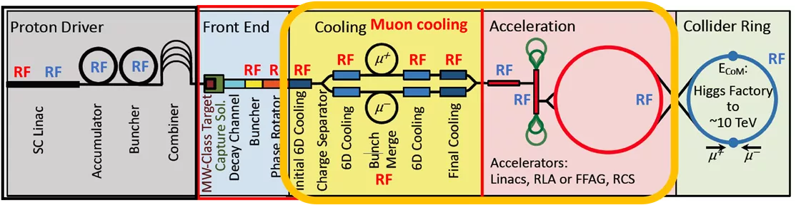
This work package focuses on assessing feasibility issues and technological challenges of RF systems for a high-energy muon collider. Tasks include defining RF systems for acceleration and cooling complexes, addressing high gradients, beam loading, breakdown mitigation, and optimizing cavity distribution. The goal is to design efficient and high-power RF sources to support muon acceleration and cooling processes in the collider.

Download Presentation

Please find below an Image/Link to download the presentation.
The content on the website is provided AS IS for your information and personal use only. It may not be sold, licensed, or shared on other websites without obtaining consent from the author. Download presentation by click this link. If you encounter any issues during the download, it is possible that the publisher has removed the file from their server.
E N D
Presentation Transcript
MuCol WP6: RF considerations for a high energy muon collider (CEA, INFN, UROS, Uni. Lancaster, CERN, Uni. Strathclyde) Claude Marchand CEA Paris-Saclay
Muon cooling RF RF RF RF RF RF RF RF RF RF RF RF RF RF RF The objective of this work package is to assess crucial feasibility issues and technological challenges of the RF systems. The study will concentrate on the two most challenging sections, the Muon Cooling Complex (MCC), and the muon acceleration stage of the High Energy Complex (HEC), for which a baseline concept of most critical RF components will be outlined based on inputs from WP4, WP5 and WP8 (cavities and RF sources). WP6 objectives: -> LDG 3.5.3, 8.2 Sustainability-Energy efficient technologies-Efficient RF sources WP6 tasks and connection to LDG R&D challenges: Task 6.2: Baseline concept of the RF system for acceleration to the High Energy Complex -> LDG 3.5.1 SRF Task 6.3: Baseline concept of the RF system for the Muon Cooling Complex -> LDG 3.5.2 NC RF Task 6.4: Break down mitigation studies for cavities of the muon cooling cells -> LDG 3.5.2 NC RF Task 6.5: Baseline concept of high efficiency and high-power RF sources for the muon collider 2
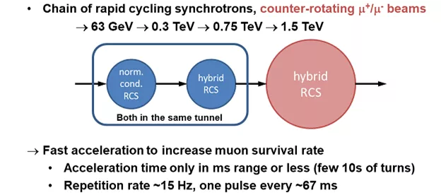
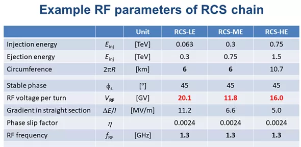
Introduction Goal: define parameter table for muon accelerator, as started by Heiko Damerau and Ivan Karpov: Task 6.2: Concept of RF systems for acceleration to HEC (RCS s) Slides from H. Damerau, MC RF WG meeting #3 Task objectives: by iterating with BD (WP5), determine a full set of parameters for all cavities addressing longitudinal beam dynamics and stability (f, R/Q, Vmax, QL, ) provide a conceptual design of cavities (eg RCS-HE) Challenges: Short muon lifetime -> huge RF voltages = need for high gradients (SRF cavities, eg XFEL like) Optimize distribution of RF cavities along the cyclotron circumference High intensity of muon bunches -> strong beam loading & wake field effects Introduction Goal: define parameter table for muon accelerator, as started by Heiko Damerau and Ivan Karpov: Slides from H. Damerau, MC RF WG meeting #3 3 Fabian Batsch F. Batsch, MC RF WG meeting #7, Jan 1, 2022 3 3 Fabian Batsch
Task 6.3: Concept of RF systems for the muon cooling complex Task objectives: by iterating with BD (WP4), determine a full set of parameters for all cavities provide a conceptual design of cavities Challenges: High beam loading Breakdown needs to be mitigated (task 6.4) Normal conducting cavities ? ~ 325 ???,650 ??? Short RF pulses (~??) High gradients (~30 MV/m) High magnetic field (up to13 T) Region Length [m] N of cavities Frequenci es [MHz] Peak Gradient [MV/m] Peak RF power [MW/cav.] Buncher 21 54 490 - 366 0 - 15 1.3 Rotator 24 64 366 326 20 2.4 Initial Cooler 126 360 325 25 3.7 Cooler 1 400 1605 325, 650 22, 30 Bunch merge 130 26 108 - 1950 ~ 10 Cooler 2 420 1746 325, 650 22, 30 Final Cooling 140 96 325 - 20 Total ~1300 3951 => ~12GW It is a very large and complex RF system with high peak power 4
Task 6.4: Break-down mitigation studies for muon cooling cell cavities Task objectives: find best cavities & RF properties to minimize breakdown due to HG in high magnetic field (material type, gas filled, temperature, pulse length, ) Methodology: 1/scaling using no-diffusion beamlet model (done) 2/develop semi-analytical model based on simulations of the electron beam in the cavity (like done in US beamlet approach) 3/adjust coefficients of semi-analytical model on existing and maybe new experimental data (UK) (MICE 200 MHz Be, MUCOOL 800 MHz Be, ) 4/test new ideas (cavity length, couplers,..) Benefits of short pulse and aluminum multiply Model developed by US labs, checked against measurements in high ?. Papers: Palmer et.al PRAB 2009, Stratakis et.al NIMPR 2010, Bowring et.al PRAB 2020 5
Task 6.5: Concept of high efficiency and high power RF sources High power L-band Multi Beam Klystrons (MBK). Commercial tubes. Task objectives: collect requirements for all RF power sources of the muon collider (f, peak power, efficiency) and identify the most challenging ones (wrt to commercially available RF sources) provide a conceptual design for those, in particular for the muon cooling section that may be used for the muon cooling demonstrator, with emphasis on high efficiency to ensure sustainability Methodology: build upon experience acquired in the HEIKA collaboration on CLIC, combining novel designs possibly scale over the range of frequencies Marginal (~10%) increase of the modulator voltage and current. and Thales : iiiiii. Mu-tube cost will be within this range, as the companies shall do it not from scratch, but could scale it from exiting ones. Though, today there is no market for such devices, thus the cost of unique prototype could be even higher. Similar to the CLIC tubes, it will take about 24 month to design, built and test the first Mu-tube prototype. Additional budget will be needed for the testing infrastructure (like RF loads etc.). CPI VKL-8301 Thales TH1801 Toshiba E3736 Canon E37503 Frequency: 1.0 GHz Peak RF power: 20 MW Efficiency: 70% Thales TH1803 Frequency: 1.3 GHz Peak RF power: 10 MW Efficiency: 65% New ideas for CLIC 1GHz klystron Scaling the Canon tube to 0.7GHz, 24MW and 30 sec. Scaling the Canon tube to 0.7GHz, 24MW and 30 sec. Canon E37503 6 beams MBK 6 beams MBK Mu-tube, 0.7 GHz Canon E37503 6 beams MBK 150 sec Mu-tube, 0.7 GHz 6 beams MBK multi beam klystron (MBK) 30 sec 171 kV 200 A 70.0 % 0.47 AxV-3/2/beam Gain = 53.9 dB Paverage(5Hz) = 3.6kW Novel design Two-stage (TS) F= P max= 20.2 MW T = V= I total = Eff.= uP= Gain = 53.9 dB P average(50Hz)= 150kW F= P max= 24 MW T = V= I total = Eff.= uP= 999,5 MHz 700 MHz To our experience such a scaling is a low risk development: For the fixed micro perveance, the tube length is proportional to the frequency Lower cathode current density (55%) and increased life time. Much lower average power (simpler collector) Marginal (~10%) increase of the modulator voltage and current. F= P max= 20.2 MW T = V= I total = Eff.= uP= Gain = 53.9 dB P average(50Hz)= 150kW Quick extrapolation F= P max= 24 MW T = V= I total = Eff.= uP= Gain = 53.9 dB Paverage(5Hz) = 3.6kW 999,5 MHz 159.4 kV 180 A 70.5 % 0.47 AxV-3/2/beam 700 MHz To our experience such a scaling is a low risk development: For the fixed micro perveance, the tube length is proportional to the frequency Lower cathode current density (55%) and increased life time. Much lower average power (simpler collector) CLIC project meeting 15 June 2021 Igor Syratchev (cern.ch) 150 sec 159.4 kV 180 A 70.5 % 0.47 AxV-3/2/beam 30 sec 171 kV 200 A 70.0 % 0.47 AxV-3/2/beam Cost and schedule: The CLIC tube prototypes were designed/built about 10 years ago; Canon: iiiii Cost and schedule: The CLIC tube prototypes were designed/built about 10 years ago; Canon: iiiii and Thales : iiiiii. Mu-tube cost will be within this range, as the companies shall do it not from scratch, but could scale it from exiting ones. Though, today there is no market for such devices, thus the cost of unique prototype could be even higher. Similar to the CLIC tubes, it will take about 24 month to design, built and test the first Mu-tube prototype. Additional budget will be needed for the testing infrastructure (like RF loads etc.). 6 Quick extrapolation
Table 3.1b Work package number 6 Lead beneficiary CEA Work package title RF considerations for a high energy muon collider Participant number CEA Uni. Lancaster UROS INFN Short name of participant Person months per participant: 24 36 12 36 Start month 1 End month 48 7
Table 3.1c : List of Deliverables Delivery date Work package number Deliverable (number) Short name of lead participant Dissemination level Deliverable name Type (in months) 6.1 6 CEA, INFN R Public 48 Report on RF for MCC and HEC (tasks 6.2,6.3,6.4) Report on design of high power and high efficiency RF power sources 6.2 6 Uni. Lancaster R Public? 42 (task 6.5) 8
Table 3.1d: List of Milestones Milestone name Means of verification Milestone number Related work package(s) Due date (in month) 6.1 6.4 24 Report approved by StCom Preliminary report on breakdown mitigation for cavities for muon cooling cells 6.2 6 .2 36 Report approved by StCom Preliminary report on RF acceleration for rapid cycling cyclotrons of HEC 6.3 6 .3 36 Report approved by StCom Preliminary set of parameters for cavities for muon cooling complex 6.4 6.5 24 Report approved by StCom Preliminary assessment of specifications for RF power sources for muon collider 9
Table 3.1e: Critical risks for implementation Description of risk (indicate level of (i) likelihood, and (ii) severity: Low/Medium/High) Work package(s) involved Proposed risk-mitigation measures 10
Thank you for attention