High-Energy Recycling in E+ E- Colliders: Energy Recovery Linacs (ERLs) Advancements
High-energy recycling in E+ E- colliders involves the innovative concept of Energy Recovery Linacs (ERLs), pioneered by experts like Vladimir N. Litvinenko. These ERLs effectively recycle energy from collided beams, reducing energy consumption and increasing collider efficiency by maximizing luminosity per AC power. The utilization of ERLs not only ensures very high luminosity and mono-energetic collisions but also promotes high polarization of electron and positron beams. This approach eliminates the need for fresh positrons, making linear colliders more sustainable and environmentally friendly. Various operational ERLs have demonstrated significant potential in multiple applications across different collider types and advanced research facilities.
Download Presentation

Please find below an Image/Link to download the presentation.
The content on the website is provided AS IS for your information and personal use only. It may not be sold, licensed, or shared on other websites without obtaining consent from the author.If you encounter any issues during the download, it is possible that the publisher has removed the file from their server.
You are allowed to download the files provided on this website for personal or commercial use, subject to the condition that they are used lawfully. All files are the property of their respective owners.
The content on the website is provided AS IS for your information and personal use only. It may not be sold, licensed, or shared on other websites without obtaining consent from the author.
E N D
Presentation Transcript
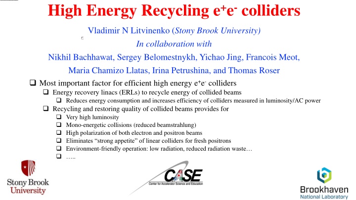
High Energy Recycling e+e-colliders Vladimir N Litvinenko (Stony Brook University) In collaboration with Nikhil Bachhawat, Sergey Belomestnykh, Yichao Jing, Francois Meot, Maria Chamizo Llatas, Irina Petrushina, and Thomas Roser Most important factor for efficient high energy e+e- colliders Energy recovery linacs (ERLs) to recycle energy of collided beams Reduces energy consumption and increases efficiency of colliders measured in luminosity/AC power Recycling and restoring quality of collided beams provides for Very high luminosity Mono-energetic collisions (reduced beamstrahlung) High polarization of both electron and positron beams Eliminates strong appetite of linear colliders for fresh positrons Environment-friendly operation: low radiation, reduced radiation waste ..
What is Energy Recovery Linacs (ERLs): Perpetua Mobile of Modern Accelerators Invented by Prof. M Tigner, Cornell U., (Nuovo Cimento 37, 1228, 1965) In principle, the idea is very simple : return energy from used beam back to the RF cavity and use it to accelerate fresh beam Extremely low losses of Superconducting RF linacs making this process very efficient with potential of many 9s in efficiency of energy recycling There is number of operational ERLs anf their potential is well understood and appreciated Return Loop Superconducting RF Linac Beam dump Gun Ez Accelerating bunch t Decelerating bunch ERLs are considered for multiple applications starting from e+e- and lepton-hadron (LHeC, FCC eh ) colliders, coolers for hadron beams (EIC), diffraction-limited light sources, X-ray FEL-divers, -ray sources, isotope production, EUV source for chip production, etc., etc. 2
Adding particle recycling in damping storage rings makes ERL-based e+e- colliders into very efficient system Gain of 40 to 200 at HIGS energy SRF linac 2 SRF linac 1 ReLiC Damp electron ring Damping positron ring CERC-100 CERC-30 FCC ee CERC Circular Energy Recovery Collider CLIC ReLiC: Recycling Linear Collider Decompress Compress / Detectors Positron source Damping rings e+ e+ Damping rings e+ e- Compress / Decompress Separator Separator Separator Separator Linac Linac e- Linac Linac Linac e+ Linac e- e- Electron source e+ e+ e+ e+ h h h h h e- h e- e+ e+ 3 h h h h e- e- e- e-
Short Summary ERL-based colliders promise significant luminosity boost in collision of polarized e+e- beam c.m. energy of ReLiC can be extended into TeV range, while multi-pass CERC would reduces length of SRF linac but limiting c.m. energy to 600 GeV in f FCC tunnel, and to HZ energy in the LHC tunnel Both CERC and ReLiC schemes can be staged, starting from operating as HZ factory using current technology and extended further with advances in SRF R&D R&D, needed on high quality (Q) SRF, flat beams and high efficiency He refrigerators has synergy with ERL R&D for EIC hadron cooler (BNL), PERLE (France), Berlin-pro, Darmstadt ERL, MESA (Germany), Test ERL (Japan) and Cbeta (Cornell) Collider efficiency : L/P ReLiC CERC Copied from F. Zimmerman's talk 150 MeV ERL for EIC coherent electron cooler of 275 GeV proton beam PERLE 4
CERC and ReLiC: polarized e+e- colliders Impact of polarization Common features Recycling used particles - no need for high intensity positron source Energy recovery High luminosity High polarization of both electron and positron beams Deference s CERC c.m. energy reach is limited to sub-TeV by synchrotron radiation of the beam at the top energy ReLiC has potential of operating at higher luminosity that CERC, ReLiC can also go to few TeV c.m. energy, but requires full energy linacs The proper combination of polarization for electrons and positrons will significantly enhance the production cross section or will suppress it.
ReLiC Recycling Linear Collider Positron source Detectors Decompress Compress / Damping rings e+ e+ Damping rings e+ e- Compress / Decompress Separator Separator Separator Separator Linac Linac e- Linac Linac Linac e+ Linac e- e- Electron source e+ e+ e+ e+ h h h h h e- h e- e+ e+ h h h h e- e- e- e- Flat beams cooled in damping rings with top off to replace burned-off particles Bunches are ejected with collision frequency, determined by the distance between beam separators Beams are accelerated on-axis in SRF linacs collide in one of detectors After collision at the top energy, they are decelerated in the opposite linacs 0,acclerating = Bunch trains are periodically separated from opposite beam, with accelerating beam propagating on-axis Fx= e Ex+vz 2eEx,decelerating postions -2eEx,decelerating electrons By c Decelerated beams are injected into cooling rings After few damping times the trip repeats in the opposite direction and beams collide in a detector located in the opposite branch of the final separator .. ReLiC collider recycles polarized electrons and positrons Reusing electron and positron beams beam cooled in damping rings provides for natural polarization of both beam via Sokolov-Ternov process. Depolarization in the trip between damping ring is minuscular, which would provide for high degree of polarization. With lifetime ~ 10 hours, necessary replacement of electrons and positrons is at 1 nA level this is major advantage of ReLiC
Baseline design Damp electron ring Damping positron ring Flat beams cooled in damping rings with top off Bunches are ejected with collision frequency Beams accelerated with SRF linacs in two four-path ERLs After collision at top energy RF phases are changed to deceleration returning most energy to SRF linac Decelerated beams are reinjected into cooling rings After few damping times the trip repeats Luminosity is shared between detectors in any desirable ratio Only beams at top energy pass through detectors, the rest of beams bypass them 100km ring Combines advantages of existing colliders: Storage ring colliders: recycling beam energy and particles Linear colliders: efficient collisions using a large disruption parameter There is probably no significant advantage of multi-pass ERL for low energy operation and Low energy CERC can be build similar to ReLiC 9
CERC parameters Damping ring energy [GeV] 2 2 2 3 4.5 8 10
ReLiC in HIGS sector Main parameters Gain of 40 to 200 at HIGS energy 240 HZ 20 250 10 2.0 12.0 38 4.0 1.0 4 0.32 1 0.01 50 199 398 365 tt_bar 30 250 12 1.7 14.4 39 4.0 1.0 4 0.56 2 0.01 64 197 395 500 HHZ 41 250 15 1.4 18.0 40 3.9 2.0 3 0.73 2 0.01 38 165 330 C.M. energy GeV ReLiC Length of accelerator Section length Bunches per train Particles per bunch Collision frequency Beam currents in linacs x, norm y, norm x y, matched z Disruption parameter, Dx Disruption parameter, Dy Luminosity per detector Total luminosity km m CERC-100 CERC-30 10 10 MHz mA mm mrad m mrad m mm mm FCC ee CLIC 1034 cm-2sec-1 1034 cm-2sec-1 11
Key technologies Decelerating e+ h h Accelerating e- CW superconducting RF (SRF) linacs with high Q 5-cell 1.5 GHz SRF cavities with effective HOM damping Electro-magnetic separators for contra-propagating bunch-trains Low emittance damping rings with flat beams and large energy acceptance Bunch compressor/decompressor MHz rate injection/ejection kickers nA-scale top-off e+e- injectors Two collision areas (IPs) Vertical beam stabilization at the IPs h Decelerating e- Decelerating e+ h Accelerating e+ h Decelerating e- 0,acclerating = Fx= e Ex+vz 2eEx,decelerating postions -2eEx,decelerating electrons By c 12
Accelerator design and challenges On-axis acceleration and deceleration of high energy beams is main advantage of ReLiC, allowing using existing SRF linac technology and other conventional equipment But still there are a lot of challenges: 1.5 GHz SRF cavities with quality factor Q > 1011 at 1.5 K High-efficiency 1.5K LiHe refrigerators Reactive tuners to reduce power to suppressing microphonics Damping rings with very flat beams ( h/ v ~2,000-4,000) Damping rings with 10% energy acceptance 10-fold bunch compressor/decompressor at 10 GeV MHz rate injection/ejection kickers Vertical beam stabilization at the IPs FoM ~75 13
Sustainability and Carbon footprint studies With current SRF technology (LSLS HE) ReLiC operating at 250 GeV c.m. energy will consume about 350 MW of AC power, which is about equally split between beam energy losses for radiation and cryogenic Increasing energy to 3 TeV c.m. with current technology will result in AC power requirement exceeding 2 GW There is potential of 5-fold in crease in Q, which would make ReLiC operation at all energy from HIGS to 3 TeV much more energy efficient. Still HIGS factory ReLiC will require ~ 200 MW of AC power, and the 3 TeV c.m. operation to under 1 GW. Current SRF technology: Q=3 1010 C.M. energy GeV MW MV MW MW MW MW 250 2 3 152 176 1 333 Suppress microphonics by RF power HOMs losses Damping rings. 70% RF efficiency Cryoplant Others. 0.1 MW/km, Total * * Future SRF technology: 1.5 K Q=1.5 1011 C.M. energy GeV MW MV MW MW MW MW 250 2 3 152 29 1 187 3000 23 12 426 349 14 824 Suppress microphonics by RF power HOMs losses Damping rings. 70% RF efficiency Cryoplant Others. 0.1 MW/km, Total RF powers needed in damping rings is proportional to ReLiC luminosity and can be reduced if 4x1036 cm- 2sec-1 luminosity is not needed. Operating 250 GeV c.m. ReLiC with luminosity of 4x1035 cm-2sec-1 will reduce accelerator power consumption to 50 MW. But the cryoplant power is proportional to the total collider energy. It can be further reduced by improving LiHe refrigerators from their current 19% (1/5th) of theoretically possible Carnot ( =T1/T2) efficiency. Investments in LiHe refrigerator R&D is probably the best chance of improving Carbon footprint of SRF system, including ReLiC. * Estimation is provided by Dr. Sergey Belomestnykh (FNAL)
Personal note (VL) I like ReLiC concept for following reasons: In contrast with ILC or CLIC, ReLiC does not suffer from huge energy spread in colliding beams introduced by beamstrahlung and from the insane appetite for fresh polarize positrons. At HIGS energy, ReLiC could provide luminosity 40x of FCC ee and 200x of ILC. In other words, boom for a buck or Luminosity per unit of AC power would be at least 100 times better. The fact that ReLiC technology can be extended to TeV range of energies 15
Proposals for upgrades and extensions Energy extension and upgrades until 1 TeV We explored possibility of extending c.m. energy in ReLiC to 3 TeV Main challenge is maintaining low energy of beamstrahlung photons This extension also requires increasing energy of damping ring Luminosity upgrades Luminosity of ReLiC can be upgraded by increasing beam currents RF power required in damping rings will grow proportionally to the beam currents, e.g. proportionally to the luminosity This proportionally allow to stage luminosity upgrades by building up ring s RF system C.M. energy Ymax E, max <Y> n E GeV 250 500 1,000 1.4E-03 707 5.9E-04 7.3E-02 2.0E-05 3,000 7.7E-04 1161 3.2E-04 2.7E-02 4.0E-06 2.4E-03 294 9.8E-04 2.0E-01 9.0E-05 2.4E-03 589 9.8E-04 9.8E-02 4.5E-05 MeV C.M. energy Length of accelerator Section length Bunches per train Particles per bunch Collision frequency Beam currents in linacs x, norm y, norm x y, matched z Disruption parameter, Dx Disruption parameter, Dy Luminosity per detector Total luminosity GeV km m 250 21 500.00 5 4.0 2.9 18 4.0 1.0 5 0.2 1 0.01 109 215 429 500 47 250.00 5 4.0 4.3 27 8.0 2.0 20 0.5 1 0.00 17 101 203 1000 93 250.00 7 3.0 6.0 29 8.0 2.0 40 1.5 3 0.00 14 67 135 3000 276 250.00 21 1.0 18.0 29 8.0 2.0 100 6.8 5 0.00 3 20 40 Classical QED !cre sx+sy ( 10 10 MHz mA mm mrad m mrad m mm mm !wc g mc2= 3g N 2 re max=2 max 2g N ( )sz ) g N!cre ( )sz !cre 3 a sx+1.85sy !cre 5 5 6g N 6g N copied... ( )sz ( )sz sxsz sx+sy sx+sy ( );Uo ( ) 2 1 ng 1.08Nare Uo sx+sy 1+ 2/3 1034 cm-2sec-1 1034 cm-2sec-1 2 0.209N2g re ) 1.20asz 3 dE= -DE ( ( ) 2 2U1 U1 sz sx+sy !cg E 1 U1 ( ) 16 1+ 2/3 ( ) 2
Strong-strong collisions of flat beams in ERL e+e- collider: Dy=142 (a) (b) (c) (d) (e) (f) Beam distribution in the vertical phase space after the collision. Distributions of the central slice are on the left and combinations of 10 slices covering evenly -3 z< z< 3 z , are on the right: (a-b) are for center particles at x=0; (c-d) are for those at x= x, (e-f) is for that at x= 2 x. The horizontal axes are the vertical coordinate and the vertical axes are vertical angle of the particle 17
Effects of orbits offsets in IP Initial beam axis separation is y=1 y Instantaneous luminosity (a.u.) Beam centroids evolution in units of y at the beam waist. Faster drop after the IP center L/Lmax Relative luminosity vs vertical beam separation 1 0.8 0.6 Geometrical Strong-Strong 0.4 0.2 y/ y 0 Main effect from offsets: RMS vertical beam emittance increases ~ 10X after collisions. It does not present any problems for the energy and particles recovery. It may require to increased time in the cooling rings to three-to- four damping times this should be optimized for actual orbit deviations 0 1 2 3 4 Reduction of the luminosity is modest actually the pinch effect continued delivering significant gain at all deviations of beam orbits 18
Important details of ReLiC design Both accelerating and decelerating beams propagate on axis of SRF cavities where transverse fields are zero. There is no need for asymmetric dual-cavities unexplored SRF technology. Focus on limiting energy spread in colliding beams We capped critical energy of beamstrahlung photons to 200 MeV and 700 MeV at c.m. energies of 240 GeV and 3 TeV, correspondingly it is significantly smaller then in ILC and CLIC We limited number of bunches in trains to keep the beam loading below 10-3* Separators use commination of DC electric and magnetic fields, which do not affect trajectory of accelerating bunches. This choice preserves emittances of colliding bunches 0,acclerating 2eEx,decelerating postions -2eEx,decelerating electrons Decelerating e+ h h Accelerating e- h Ex= -vz Decelerating e- cBy Decelerating e+ h Accelerating e+ = Fx= e Ex+vz h By c Decelerating e- * Even though, the energy of each colliding bunch is known and can be used for data analysis. If this feature is used, luminosity can be further increased 19
Important consideration At high energies the most dangerous effect is beamstrahlung: synchrotron radiation in strong EM field of opposing beam during collision It can cause significant amount of energy loss, induce large energy spread and loss of the particles Using very flat beams is the main way of mitigating this effect Our goal was to maintain energy spread in colliding beams at the same level as in ring-ring FCC ee: 0.15-0.2% 3 p 3N2 re 2sz Dg =4 g2; sx 9 for sx>>sy 20
CERC beam energy evolution in 4-pass ERL Ebeam= 250 GeV Ebeam= 182.5 GeV 21
