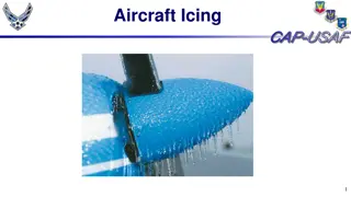
Electrified Aircraft Thermal Research and Ice Protection Systems
Explore the heat flux requirements for electrified aircraft wing anti-ice systems, managed through passive Thermal Management Systems in the High-efficiency Electrified Aircraft Thermal Research project. The project aims to increase efficiencies in electric components, featuring representative aircraft configurations like STARC-ABL, PEGASUS, and RVLT, highlighting the importance of considering ice protection system requirements early in the design phase to ensure power availability. Flight profiles of STARC-ABL and PEGASUS depict potential icing conditions encountered during various phases of flight.

Download Presentation

Please find below an Image/Link to download the presentation.
The content on the website is provided AS IS for your information and personal use only. It may not be sold, licensed, or shared on other websites without obtaining consent from the author. Download presentation by click this link. If you encounter any issues during the download, it is possible that the publisher has removed the file from their server.
E N D
Presentation Transcript
TFAWS Interdisciplinary Paper Session Heat Flux Requirements for Electrified Aircraft Wing Anti-Ice Systems Nic Heersema NASA Armstrong Flight Research Center Thermal & Fluids Analysis Workshop TFAWS 2020 August 18-20, 2020 Virtual Conference
High-efficiency Electrified Aircraft Thermal Research (HEATheR) The project goals: Increase efficiencies of electric components to reduce waste heat generated Manage waste heat using passive Thermal Management System (TMS) 3 representative aircraft considered: Single-aisle Turboelectric AiRCraft with Aft Boundary Layer propulsion (STARC-ABL) 2 underwing turbofans drive an electric Boundary Layer Ingestion (BLI) motor Parallel Electric-Gas Architecture with Synergistic Utilization Scheme (PEGASUS) Parallel hybrid-electric turboprop outboard engines, inboard all- electric engines, aft all-electric BLI motor Revolutionary Vertical Lift Technology (RVLT) Tiltwing VTOL with a central turboshaft engine driving 4 electric wing motors Ice protection system requirements need to be considered early in design phase to ensure sufficient excess power/bleed air available TFAWS 2020 August 18-20, 2020 2
Flight Profile: STARC-ABL Icing conditions could be encountered during Takeoff, Climb, Descent, and Holding Altitude (ft) AoA (deg) Temp (degF) Temp (degK) Droplet (microns) LWC (g/m^3) Duration (mins) Run Number Mach No. Envelope WB41 T = -13 IRT Run 1.07 IRT Run 2.03 WB33 T = -4 IRT Run 1.26 IRT Run 1.05 WB39 T = -25 WB37 T = -7 IRT Run 1.19 IRT Run 1.29 5000 5000 10000 10000 15000 15000 22000 15000 10000 15000 0.36 0.33 0.35 0.36 0.39 0.33 0.36 0.46 0.39 0.40 0 0 0 0 0 0 0 0 0 0 8.6 21.5 14 24.8 0 0 -13 20 10 0 260.15 267.3167 263.15 269.15 255.372 255.372 248.15 266.483 260.928 255.372 20 20 20 20 35 20 20 35 20 20 0.361 0.504 0.415 0.551 0.095 0.248 0.175 0.19 1.807 1.56 45 45 45 45 45 45 45 45 8 8 Cont. max Cont. max Cont. max Cont. max Cont. max Cont. max Cont. max Cont. max Int. max Int. max TFAWS 2020 August 18-20, 2020 3
Flight Profile: PEGASUS 400 nm 200 nm ~300 nm Profiles: All-Electric: 200 nm range Hybrid-Electric: 400 nm range Reserves: 87 nm + 45 minutes Icing conditions could be encountered during all phases of flight Altitude (ft) AoA (deg) Temp (degF) Temp (degK) Droplet (microns) LWC (g/m^3) Duration (mins) Run Number Mach No. Envelope WB41 T = -13 IRT Run 1.12 IRT Run 2.03 WB33 T = -4 IRT Run 1.26 IRT Run 1.05 Cruise T = -25 Cruise T = -16.7 5000 5000 10000 10000 15000 15000 20000 20000 0.36 0.36 0.35 0.36 0.39 0.33 0.45 0.44 0, 4.5 0, 4.5 0, 4.5 0, 4.5 0, 4.5 0, 4.5 0, 4.5 0, 4.5 8.6 20 14 24.8 0 0 -13 2 260.15 266.483 263.15 269.15 255.372 255.372 248.15 256.483 20 35 20 20 35 20 20 35 0.362 0.19 0.425 0.553 0.096 0.26 0.177 0.105 45 45 45 45 45 45 45 45 Cont. max Cont. max Cont. max Cont. max Cont. max Cont. max Cont. max Cont. max TFAWS 2020 August 18-20, 2020 4
Flight Profile: RVLT Icing conditions could be encountered during all phases of flight Altitude (ft) AoA (deg) Temp (degF) Temp (degK) Droplet (microns) LWC (g/m^3) Duration (mins) Run Number Mach No. Envelope WB41 T = -13 IRT Run 2.02 IRT Run 2.03 IRT Run 2.05 FT#1 5000 500 5000 500 5000 0.271 0.267 0.269 0.273 0.270 0, 8 0, 8 0, 8 0, 8 0, 8 8.6 20.2 14 0 11 260.15 266.59 263.15 255.372 261.483 20 35 20 20 40 0.362 0.192 0.425 0.26 0.421 45 45 45 45 8 Cont. max Cont. max Cont. max Cont. max Int. max TFAWS 2020 August 18-20, 2020 5
Types of Ice Protection Systems ThermoPneumatic ElectroThermal Used primarily for: Propeller blades Wing anti-ice/de-ice on smaller planes Wing de-ice on 787 Dreamliner Windshields Reduced energy requirements, drag, and noise compared to ThermoPneumatic Heat transfer: information not available Requirements: Weight: Lighter than bleed-air system, ~0.25 9.4 kg/m Power: 45-75 kW TSFC Penalty: ~1-2% while system active Risks/concerns: Overheat (when used with Al alloys) Power must be extracted from engine (performance impact) or a separate generator (weight penalty) In use on most large turbojets Bleed air extracted from engine fed through ducting, manifolds, valves, and pipes to leading edge ~1.13-1.36 kg/s @ 0.26 MPa per wing Performance impact from bleed air extraction Heat transfer per unit span: ~ 1-5 kW/m Requirements: Weight: ~140-270 kg (737-size aircraft) Power: information not available TSFC Penalty: ~2.5-4.5% while system is active Risks/concerns: Air leakage from system Overheat 6 TFAWS 2020 August 18-20, 2020 6
Types of Ice Protection Systems Running Wet (RW) Fully evaporative (FE) Heats the incoming water to maintain temperature above freezing over heated section of wing chord Water freezing on wing aft of heated section is called runback ice Often requires a de-icer to handle runback ice Lower heat transfer/power requirements Commonly employed as a parting strip on the leading edge of wing to assist with de-icing Evaporates incoming water on contact No runback icing No de-icer required Localized to small area around leading edge of wing Higher heat transfer/power requirements Commonly used for windshields TFAWS 2020 August 18-20, 2020 7 7
Analysis of Anti-Ice Heat Requirements Heat flux requirements calculated using LEWICE2D for various icing conditions 1D steady state analysis performed 2D analysis performed with ANSYS FENSAP-ICE Heat flux calculation not validated yet FENSAP max heat flow rate requirements are generally lower for both Running Wet and Fully Evaporative Typical airplane Carbon-Fiber Reinforced Polymer material assumed Heat flow rate requirements with 6061 Al are ~3% lower for STARC-ABL Heat flow rate calculation assumes entire wing covered Icing conditions selected are a mix from NASA Common Research Model 65% scale model and platform-specific icing flight conditions Last 2 scenarios for STARC-ABL and RVLT cover more severe intermittent icing conditions and may not require the wing to be entirely free of ice for the short duration More refined icing analysis would be required to determine impact to handling characteristics and performance from ice buildup in different regions of the wing TFAWS 2020 August 18-20, 2020 8
STARC-ABL Anti-Ice Heat Requirements Heat flow rate required for 10% chord anti-ice per wing at different icing conditions: Droplet size (microns) LWC (g/m^3) 20 20 20 20 35 20 20 35 20 20 Heat flow rate (kW), RW Max heat flux @ LE (kW/m^2), FE Temp (degF) Heat flow rate (kW), FE Scenario Alt (ft) 1 2 3 4 5 6 7 8 9 10 Mach 5000 5000 10000 10000 15000 15000 22000 15000 10000 15000 0.36 0.33 0.35 0.36 0.39 0.33 0.36 0.46 0.39 0.40 8.60 21.5 14.0 24.8 0.361 0.504 0.415 0.551 0.095 0.248 0.175 0.190 1.807 1.560 53.05 32.36 40.14 13.11 47.64 47.43 55.85 4.380 50.61 62.25 40.97 43.77 44.06 55.46 41.86 34.37 31.97 77.72 166.9 222.2 102.9 108.5 108.8 127.2 46.44 77.67 63.49 76.38 411.2 470.3 0 0 -13.0 20.0 10.0 0 Key: Heat flow requirements are within capability of thermopneumatic AI/DI system > 5 kW/m (91 kW) > 2.5 kW/m (46 kW) < 2.5 kW/m (46 kW) TFAWS 2020 August 18-20, 2020 9
PEGASUS Anti-Ice Heat Requirements Heat flow rate required for 10% chord anti-ice per wing at different icing conditions: Droplet size (microns) LWC (g/m^3) 20 35 20 20 35 20 20 35 Heat flow rate (kW), RW Max heat flux@ LE (kW/m^2), FE Temp (degF) Heat flow rate (kW), FE Scenario Alt (ft) 1 2 3 4 5 6 7 8 Mach 5000 5000 10000 10000 15000 15000 20000 20000 0.36 0.36 0.35 0.36 0.39 0.33 0.45 0.44 8.60 20.0 14.0 24.8 0.362 0.190 0.425 0.553 0.096 0.260 0.177 0.105 77.03 49.91 53.65 19.23 68.90 69.67 88.73 59.81 86.38 104.7 90.26 123.4 72.45 61.19 86.69 87.13 96.42 69.14 87.84 126.3 47.03 59.09 78.11 53.20 0 0 -13.0 20.0 Key: > 5 kW/m (60 kW) > 2.5 kW/m (30 kW) < 2.5 kW/m (30 kW) Heat flow requirements exceed current capabilities of thermopnuematic AI/DI system. Analysis in de-ice mode should be performed and/or area coverage should be reduced. TFAWS 2020 August 18-20, 2020 10
RVLT Anti-Ice Heat Requirements Heat flow rate required for 10% chord anti-ice per wing at different icing conditions: Heat flow rate (kW), RW Heat flow rate (kW), FE Max heat flux @ LE (kW/m^2), FE Temp (degF) Droplet size (microns) LWC (g/m^3) Scenario Alt (ft) 1 5000 2 3 4 5 6 7 8 9 10 Mach 0.271 0.267 0.269 0.273 0.271 0.267 0.269 0.273 0.270 0.270 AoA 0 0 0 0 8 8 8 8 0 8 8.6 20 14 20 35 20 20 20 35 20 20 40 40 0.361 0.192 0.425 0.260 0.361 0.192 0.425 0.260 0.421 0.421 50.2 48.8 41.7 44.4 48.9 47.7 41.2 61.4 49.2 54.0 57.3 57.4 63.7 65.8 50.9 50.6 60.5 43.0 157 163 68.3 47.8 77.2 53.7 72.4 52.8 80.3 59.6 102 113 500 5000 500 5000 500 5000 500 5000 500 0 8.6 20 14 0 11 11 Key: LEWICE not designed to handle locations immediately downstream of a rotor so the validity of these values uncertain More refined analysis required > 5 kW/m (36 kW) > 2.5 kW/m (18 kW) < 2.5 kW/m (18 kW) TFAWS 2020 August 18-20, 2020 11
Integration Considerations Heat flux at leading edge required for fully evaporative system might not be achievable given material and heat transfer constraints Running wet system will likely require de-icer to handle runback ice Detailed analysis required to evaluate effect of runback ice on handling characteristics and performance and determine need for de-icer De-icer adds weight and power requirements compared to fully evaporative system Electro-mechanical expulsion deicing system (EMEDS) in use on several aircraft is a lightweight, low power option Weight: ~23 kg Power requirement: ~23-33 W/m (total for STARCABL: ~1 kW) Power requirement can be reduced through use of anti-ice coating TFAWS 2020 August 18-20, 2020 12
Conclusions Heat requirements calculated for maintaining ice free leading edge for 3 HEATheR variant aircraft Heat requirements in excess of capabilities of typical thermopneumatic AI/DI systems Further analysis to determine heat requirements in cyclic de-ice mode recommended for at least PEGASUS and RVLT More refined analysis required LEWICE not designed for wing surfaces directly aft of rotors - RVLT results may not be valid Analysis required to determine effect of ice accretion on aerodynamics and handling characteristics Testing to validate results desired Takeoff angle of attack for STARC-ABL and PEGASUS is above range previously validated for LEWICE TFAWS 2020 August 18-20, 2020 13
Acknowledgements Convergent Aeronautics Solutions (CAS) for funding NASA Glenn Research Center Icing Branch for their support Eric Stewart for determining the icing conditions to analyze and generating FENSAP results Bill Wright for assistance with LEWICE NASA Ames Research Center for CFD analysis TFAWS 2020 August 18-20, 2020 14
QUESTIONS? TFAWS 2020 August 18-20, 2020 15
BACKUP TFAWS 2020 August 18-20, 2020 16
Sample Analysis Results LEWICE vs FENSAP Max heat flux @ LE (kW/m^2), EVAP Droplet size (microns) LWC (g/m^3) 20 Heat flow rate (kW), RW Temp (degF) Heat flow rate (kW), EVAP Scenario Alt (ft) 3 Mach 10000 0.35 14 0.415 40.14 44.06 108.8 LEWICE Results Ice accretion without anti-ice FENSAP Results TFAWS 2020 August 18-20, 2020 17