Understanding MIMO and Spatial Multiplexing in Wireless Networks
Graphical intuition and physical modeling of SIMO and MIMO channels, addressing the problem of wireless interference and leveraging multiple antennas for improved reception. Exploring concepts like zero-forcing receivers and spatial multiplexing for increased capacity and rate speed-up in wireless communication.

Download Presentation

Please find below an Image/Link to download the presentation.
The content on the website is provided AS IS for your information and personal use only. It may not be sold, licensed, or shared on other websites without obtaining consent from the author. Download presentation by click this link. If you encounter any issues during the download, it is possible that the publisher has removed the file from their server.
E N D
Presentation Transcript
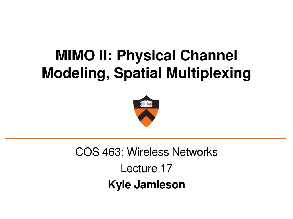
MIMO II: Physical Channel Modeling, Spatial Multiplexing COS 463: Wireless Networks Lecture 17 Kyle Jamieson
Today 1. Graphical intuition in the I-Q plane 2. Physical modeling of the SIMO channel 3. Physical modeling of the MIMO channel 2
The problem of wireless interference User A Channel Access Point (AP) I-Q plot: A send Channel AP receive AP can estimate the channel, so can decode User A s signal ( ) 3
The problem of wireless interference User B I-Q plot: B send Channel AP receive AP can estimate the channel, so can decode User B s signal ( ) 4
The problem of wireless interference User B User A I-Q plot: AP receive from A alone AP receive from B alone AP receive (A + B) 5
Leveraging Multiple Antennas Now, the AP hears two received signals, one on each antenna: 2 Antenna 1 User A Access Point User A Antenna 2 Send Antenna 1 6
Leveraging Multiple Antennas User B Antenna 1 User A 2 Mixture of A and B User B User A A2 Antenna 2 A2 = + A1 A1 Antenna 1 7
Intuition: Zero-Forcing Receiver MIMO zero-forcing receiver 1. Rotateone antenna s signal ( ) 2. Sumthe two antennas signals together ( + ) User B User A Sum Sum A2 A2 A1 A1 Rotate Rotate 8
Spatial Multiplexing: More Streams Send multiple streams of informationover each of the spatial paths between sender and receiver This is called spatial multiplexing Potential for increased capacity by a factor of N (minimum number of send or receive antennas): ( )bits/s/Hz C=BNlog 1+SNR Potential for a multiplicative rate speed-up 9
Today 1. Graphical intuition in the I-Q plane 2. Physical modeling of the SIMO channel 3. Physical modeling of the MIMO channel 10
Physical Modeling of Multi-Antenna Channels Gain intuition as to how the RF channel (ambient environment) impacts capacity Many physical antenna arrangement geometries possible Limit discussion today to linear antenna arrays, half- wavelength antenna spacing Details vary with more sophisticated antenna arrangements, but concepts do not 11
Line-of-Sight SIMO Channel: A Second Look ? ? ? ?/2 antenna separation 1 Sendx 2 3 Receivey1, y2,y3 ?1 ?2 ?3 Vector notation for the system: = ? = ? + ? ???2??1 ???2??2 ???2??3 Wireless channel is now a three-tuple vector: = 12
Line-of-Sight SIMO Channel: A Second Look ? ? ? ?/2 antenna separation 1 Sendx 2 3 Receivey1, y2,y3 ???2??1/ ???2??2/ ???2??3/ Wireless channel is now a three-tuple vector: = Wireless channel: Antenna separations: Assume ?1= ? ?2 ? +1 ?3 ? +?cos? 1 = ???2??/? ??? cos ? ??2? cos ? 2?cos? 13
Line-of-Sight SIMO Channel: Spatial Signature ? ? ? ?/2 antenna separation 1 Sendx 2 3 Receivey1, y2,y3 The wireless channel decomposes into two components: 1 = ???2??/? ??? cos ? ??2? cos ? Path component Spatial Signature The angle of arrivalof the sender s signal at the receive array determines the spatial signature 14
Line-of-Sight SIMO Channel: Maximal Ratio Combining (Review) ? ? ? ?/2 antenna separation 1 Sendx 2 3 Receivey1, y2,y3 Maximal ratio combining projects the received signals ?onto the receive spatial signature: ? = ? Reverses the phases in the spatial signature to aligneach antenna s component of the above sum SNR improvement but no multiplexing 15
Today 1. Graphical intuition in the I-Q plane 2. Physical modeling of the SIMO channel 3. Physical modeling of the MIMO channel Line-of-Sight MIMO Channel Geographically-Separated Transmit Antennas Geographically-Separated Receive Antennas MIMO Link in Multipath 16
The Line-of-Sight MIMO Channel Sendx1, x2, x3 1 2 3 ? 1 ?/2 antenna separation ?/2 2 3 ? ? ? Receivey1, y2,y3 ?1 ?2 ?3 Want to transmit three symbols per symbol time: ? = ???: channel between k th receive and lth transmit antenna 11 21 31 12 22 32 11 11 11 ? = H H ?, where H H = is the MIMO channel matrix 17
The Line-of-Sight MIMO Channel: Channel Matrix Sendx1, x2, x3 1 2 3 ? 1 ?/2 antenna separation ?/2 2 3 ? ? ? Receivey1, y2,y3 ???: channel between k threceive and lthtransmit antenna Suppose as before, ?11= ? Then ???= ? +1 2? 1 cos? +1 2? 1 cos? Tx 2: Tx 3: Tx 1: ??? ??? ? ??? (cos?+cos?) ??? (2cos?+cos?) ??? 2cos? ??? (cos?+2cos?) ??? (2cos?+2cos?) 1 Channel matrix ? = ???2??/? ??? cos? ??2? cos? 18
The Line-of-Sight MIMO Channel: Identical Spatial Signatures Sendx1, x2, x3 1 2 3 ? 1 ?/2 antenna separation ?/2 2 3 ? ? ? Receivey1, y2,y3 Tx 3: Tx 2: Tx 1: ??? ??? ? ??? (cos?+cos?) ??? (2cos?+cos?) ??? 2cos? ??? (cos?+2cos?) ??? (2cos?+2cos?) 1 Channel matrix ? = ???2??/? ??? cos? ??2? cos? Transmit antenna 2 s channel and spatial signature: 12 22 32 1 = ???2?? ?+cos? ??? cos? ??2? cos? 19
The Line-of-Sight MIMO Channel: Takeaways Spatial signature: How to phase-shift received signals to align them Spatial signature of Transmit antenna 1 Equals spatial signature of Tx antenna 2, Tx antenna 3 So any receiver attempt to align signal from Transmit antenna 1 Also aligns transmit antennas 2 and 3 Result is interference between x1, x2, x3 Can send same single symbol x on all transmit antennas Results in same power gain as MRC 20
Today 1. Graphical intuition in the I-Q plane 2. Physical modeling of the SIMO channel 3. Physical modeling of the MIMO channel Line-of-Sight MIMO Channel Geographically-Separated Transmit Antennas Geographically-Separated Receive Antennas MIMO Link in Multipath 21
Geographically-Separated Transmit Antennas: Space-Division Multiple Access (SDMA) Sendx1, x2 1 1 ?/2 antenna separation ? ?2 2 ?1 2 Receivey1, y2 Tx 1: Tx 2: 1 1 Channel matrix ? = ???2??/? ??? cos ?1 ??? cos ?2 Sig. 2 Sig. 1 Different spatial signatures for Transmit Antenna 1,2 22
Spatial Signature = Series of Phase Differences Tx 1: Tx 2: 1 1 Channel matrix ? = ???2??/? ??? cos ?1 ??? cos ?2 Sig. 2, ??? Sig. 1, ??? From Transmit Antenna 2: From Transmit Antenna 1: At Receive Antenna 1 At Receive Antenna 1 + Sig. 1 Sig. 2 At Receive Antenna 2 At Receive Antenna 2 23
The Zero-Forcing Receiver (via Spatial Signatures) Suppose want to receive from Transmit Antenna 1 (Recall:) Rotate Receive Antenna 2 s signal so that Signature 2 cancels itself From Transmit Antenna 2: From Transmit Antenna 1: At Receive Antenna 1 At Receive Antenna 1 + Sig. 1 Sig. 2 At Receive Antenna 2 At Receive Antenna 2 24
The Zero-Forcing Receiver (via Spatial Signatures) ??? ? One spatial signature = One direction Zero forcing Antenna 2 is projection Onto subspace to ??? ??? From Transmit Antenna 2: From Transmit Antenna 1: At Receive Antenna 1 At Receive Antenna 1 + Sig. 1 Sig. 2 At Receive Antenna 2 At Receive Antenna 2 25
MIMO Separability: Discussion Transmit antenna separation Spatial signature separation Better projection, Better performance ??? ? ??? MIMO antenna array without multipath No transmit antenna separation No spatial signature separation Cancel Tx Ant 2: cancels Tx Ant 1 No spatial multiplexing ??? ? ??? 26
Today 1. Graphical intuition in the I-Q plane 2. Physical modeling of the SIMO channel 3. Physical modeling of the MIMO channel Line-of-Sight MIMO Channel Geographically-Separated Transmit Antennas Geographically-Separated Receive Antennas MIMO Link in Multipath 27
Geographically-Separated Receive Antennas: SDMA Downlink Different spatial signatures for Receive Antennas 1,2 Rows, instead of columns in the MIMO matrix 28
MIMO in Multipath 1 Antenna 1 2 d1 Transmitter Antenna 2 Receiver Antenna 1 1 d2 Antenna 2 2 Tx antenna 2: Tx antenna 1: ?1??2??1 ?+cos?1+cos?1+?2??2??2 ?+cos?1+?2??2??2 ?+cos?2 ?1??2??1/?+?2??2??2/? ?1??2??1 H H = ?+cos?1+?2??2??2 ?1??2??1 ?+cos?2 ?+cos?2+cos?2 Neither column is a multiple of the other So H has two different transmit antenna spatial signatures 29
Different Spatial Signatures: Intuition 1 Antenna 1 2 d1 Transmitter Antenna 2 A Receiver Antenna 1 1 d2 Antenna 2 2 B Channel matrix H has two different spatial signatures Imagine perfect signal relays A, B This H is the product of: Geographically-separated receive antenna channel Geographically-separated transmit antenna channel 30
Poorly-Conditioned MIMO channels Receiver !1 Antenna 1 !2 Transmitter Antenna 2 Only reflectors near receiver: 1 2 Antenna 1 "1 Antenna 2 "2 !1 Antenna 1 !2 Transmitter Antenna 2 Only reflectors near transmitter: 1 2 Receiver Antenna 1 "1 Antenna 2 "2 h1 h2 When channel is poorly conditioned, spatial signatures are closer aligned 31
How Many Streams are Possible? Received signals live in an nr-dimensional vector space e.g.nr = 3 receive antennas 3-D vector space: Cancel by projection. Therefore, at most nr streams possible 32
How Many Streams are Possible? One spatial signature per transmit antenna e.g.nr = 3 receive, nt = 2 transmit antennas: h2 h1 Therefore, at most nt streams possible 33
How Many Streams are Possible? Need enough strong physical paths in the wireless channel e.g.nr = 3, nt= 3buttwo physical paths confines { hi} to a plane h2 h3 h1 At most # physical paths possible streams 34
How Many Streams are Possible? Need enough strong physical paths in the wireless channel e.g.nr = 3, nt= 3 and three physical paths h1 Proj Proj ?2,?3?1 h2 h3 h1 At most # physical paths possible streams 35
Degrees of Freedom The figure of merit that summarizes the number of streams possible is called the number of degrees of freedom of H h1 h2 h3 Degrees of freedom = min { nt , nr , # strong paths } 36
Summary Spatial multiplexing requires either: Spatially-separated receivers / transmitters (SDMA), or Multiple antennas at both ends of a link (MIMO), and Enough physical channel propagation paths Degrees of freedom quantify spatial multiplexing potential 37
Tuesday Topic: MIMO III: Channel Capacity, Interference Alignment 38