Water Demand Calculation Methods for Plumbing Fixtures
The water demand at individual water outlets can be calculated by considering the maximum flows from various plumbing fixtures and applying a factor to estimate the total required design flow rate. Two methods, individual water outlets and Hunter's method, are used to determine the hot, cold, and total water flow rates in a building. Additionally, continuous water demand calculations and sizing requirements for heaters and storage tanks in an apartment building are discussed based on the number of fixtures.

Download Presentation

Please find below an Image/Link to download the presentation.
The content on the website is provided AS IS for your information and personal use only. It may not be sold, licensed, or shared on other websites without obtaining consent from the author. Download presentation by click this link. If you encounter any issues during the download, it is possible that the publisher has removed the file from their server.
E N D
Presentation Transcript
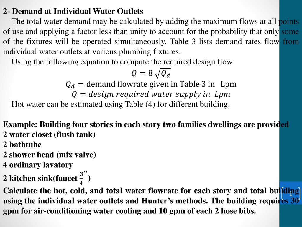
2- Demand at Individual Water Outlets The total water demand may be calculated by adding the maximum flows at all points of use and applying a factor less than unity to account for the probability that only some of the fixtures will be operated simultaneously. Table 3 lists demand rates flow from individual water outlets at various plumbing fixtures. Using the following equation to compute the required design flow ? = 8 ??= demand flowrate given in Table 3 in Lpm ? = ?????? ???????? ????? ?????? ?? ??? Hot water can be estimated using Table (4) for different building. ?? Example: Building four stories in each story two families dwellings are provided 2 water closet (flush tank) 2 bathtube 2 shower head (mix valve) 4 ordinary lavatory 2 kitchen sink(faucet? ? Calculate the hot, cold, and total water flowrate for each story and total building using the individual water outlets and Hunter s methods. The building requires 30 gpm for air-conditioning water cooling and 10 gpm of each 2 hose bibs. ) 1
Solution: Individual Water Outlets Demand gpm Cold water Hot water Fixture type Quantity w.c 2 3 6 - bathtube 2 5 10 - bathtube 2 0.333 - 0.667 shower 2 5 10 - shower 2 0.5 - 1 Lavatory 4 2 8 - Kitchen sink 2 6 12 - Kitchen sink 2 0.17 - 0.333 Total 46 2 Cold Water ? = 8 ?? ? 2 ? = 8 46 3.786 = 105.6 ??? ? ??? ??? ??? ????? ? = 8 46 3.786 4 = 211.1 ??? ????? ????????
Continuous water demand = 30 + 10 2 = 50 gpm 105.6 + 50 3.786 = 294.9 ? ??? for each story ? ??? for total building 211.1 + 50 3.786 = 400.4 Hot Water ? ? ? = 2 0.3 = 0.6 ???= 2.272 ? ???= 9.1 ??= 46 + 2 = 48 ??? ??? ? ??? ??? ????? ???????? ??? ??? ????? ? = 0.6 4 = 2.4 ??? ????? ???? ?? + ???? = ? ? = 8 48 3.786 = 107.85 ??? ? 107.85 + 50 3.786 = 297.15 ??? ??? ??? ????? ? ? = 8 48 3.786 4 = 215.7 ??? ? 215.7 + 50 3.786 = 405 ??? ??? ????? ???????? 3 2 - Hinter s method
Hot water Cold water Fixture type Quantity F.U Total w.c 2 5 - 10 10 bathtube 2 3 6 6 - bathtube 2 4 - - 8 shower 2 3 6 6 - shower 2 4 - - 8 lavatory 4 1.5 6 6 - lavatory 4 2 - - 8 Kitchen sink 2 3 6 6 - Kitchen sink 2 4 - - 8 Total of each story 24 34 42 Hot Water For each story 24 f/u=15 gpm for total building 96 f/u= 43 gpm Cold Water for each story 34 f/u= 23 gpm for total building 136 f/u = 52 gpm Total flow for each story 42 f/u = 48 gpm for total building 168 f/u = 86 gpm 4
Continuous demand 30 + 2 10 = 50 gpm Hot water = 15 gpm for each story = 43 gpm for total building Cold water 23+50 = 73 gpm for each story 52 + 50 = 102 gpm for total building Total flow 48 + 50 = 98 gpm for each story 86 + 50 =136 gpm for total building Example: Determine heater and storage tank size for an apartment building from a following number of fixtures. Flow per fixture gal/hr Hot water demand gal/hr Quantity Lavatories (private) 60 2 120 30 bathtubs 20 600 30 showers 30 900 60 kitchen sink 10 600 5 15 lundry tubs 20 300 2520
Probable maximum demand = 0.3 2520 Storage tank capacity = 1.25 756 = 756 gph = 945 gal Static head It is the measure of elevation of water above a reference point. Dynamic head It is static head minus the friction loss of a flowing liquid, expressed as shown in Fig. Friction head loss Static head Dynamic head 6 The water distribution system must be always be designed on basis of the minimum pressure available. Generally, the minimum pressure to be provided at most fixture is 8 psi (55 kpa) and
from 15 to 25 psi for water closet. Friction head loss Water piping must be sized to limit the friction head losses in the piping system so that the highest and most remote water outlet will have the required minimum pressure head for adequate flow during periods of peak demand. The maximum friction head loss that can therefore be tolerated in the system during peak demand is the difference between the static pressure at the highest and most remote outlet at no flow conditions and the minimum flow pressure required at that outlet. For brass, copper, or plastic piping ?= 0.000623 ?2? ??= 0.00027 ?2? For galvanized-steel and wrought-iron piping ?= 0.001246 ?2? ??= 0.000539 ?2? ?= ??? ???? ??? ?? ???????? ?? ??= ???????? ????, ??? ?5 ?? ?5 ?5 ?? ?5 7
? = ???????? ?? ????, ? = ?????????? ????? ?? ??????, ??= 1.5 ? ? = ???????? ?? ??????, ??? ?? ??. Using Hizen-Williamz Eq. ? = 0.2784 ? ?2.63?0.54 , ?3/? For greater accuracy , it was suggested that water supply pipe be considered in four classes as to hydraulic roughness: ??? ????? ???? ??? ?????? ????? ???? ??? ?????? ???? ???? ??? ???? ???? ? = 4.93 ?0.571 ?2.714 ? = 4.57 ?0.546 ?2.64 ? = 4.29 ?0.521 ?2.562 ? = 3.7 ?0.5 ?2.5 ? = ???????? ???? ?? ????, ? = ???????? ???? ??? ?? ????????,??? ??? ?? ???? ????? 100 ? = ???????? ?? ????, ??. 8
Example There is 4-story building where the street pressure is reported as 22 m. Design the pipes of water supply network shown in Fig. if the pipes are galvanized-steel piping. ? F 14 m 3.5 m 240 l/min ? E 14 m 240 l/min 3.5 m ? D 14 m 240 l/min 3.5 m ? C 240 l/min 14 m 3m A B 25 m ?= 0.001246 ?2? ?5 ?= 22 13.5 5.61 = 2.89 ? ??= 1.5 52.5 = 78.75 ? ????? ?? ???????? ???????? = ? ?= 0.037 To find slope of hydraulic pressure of branches C? ,?? ,?? ,??? ?? ?? ???????: Point C : ?= 22 28 0.037 3 5.61 = 12.354 ? ??= 14 1.5 = 21 ? 9 ? = 0.588
Point D: ?= 22 31.5 0.037 6.5 5.61 = 8.725 ? ??= 1.5 14 = 21 ? ? = 0.415 ? Point L S C 12.354 21 0.588 D 8.725 21 0.415 E 5.095 21 0.243 F 1.466 21 0.07 Total Discharge l/min Design Discharge, l/min Cal. Sel. Pipe Slope Diameter, mm Diameter, mm ABC 0.037 960 248 68.7 70 CD 0.037 720 215 64.9 70 DE 0.037 480 175 59.8 60 EF 0.037 240 124 52.1 55 CC 0.588 240 124 29.9 30 DD 0.415 240 124 32.1 35 10 EE 0.243 240 124 35.7 40 FF 0.07 240 124 45.8 50
Example: Design pipes of water supply network shown in Fig. Using Hizen-Williamz Eq. for steel Pipes ? = 0.2784 ? ?2.63?0.54 , C=100 A B Storage tank 20 m 7.5 m ? 14 m C 240 l/min 3.5 m 14 m ? D 3.5 m 240 l/min 14 m ? E 3.5 m 240 l/min 14 m ? F 3.5 m 240 l/min ? 14 m G 240 l/min 11 3.5 m ? 14 m H 240 l/min
Solution: Line ABCC ?= 7.5 5.61 = 1.89 ? Calculation of friction loss and slope of pressure hydraulic ? = 41.5 1.5 = 62.25 ? 1.89 62.25= 0.03 ? = ? Line L S ABCC 1.89 62.25 0.03 ABDD 5.39 67.5 0.08 ABEE 8.89 72.75 0.122 ABFF 12.39 78.0 0.159 ABGG 15.89 83.25 0.191 ABHH 19.39 88.5 0.219 Minimum S = 0.03 Calculation ? at points and slopes of pressure Point C: ?= 7.5 0.03 27.5 5.61 = 1.065 ? 12 ? = 14 1.5 = 21 ? ? = 0.051
? Points L S C 1.065 21 0.051 D 4.46 21 0.212 E 7.855 21 0.374 F 11.25 21 0.536 G 14.645 21 0.697 H 18.04 21 0.859 ??,?/??? 1440 ??,?/??? Dia. Cal. , mm 303.6 Pipes S Dia. sel. , mm ABC 0.03 78 80 CD 0.03 1200 277.1 75.2 80 DE 0.03 960 247.9 72.1 75 EF 0.03 720 214.7 68.2 70 FG 0.03 480 175.3 63.2 65 GH 0.03 240 123.9 55.3 60 13 CC 0.051 240 123.9 49.6 50 DD 0.212 240 123.9 37.1 40
??,?/??? 240 ??,?/??? Dia. Cal. , mm 123.9 Pipes S Dia. Sel. , mm EE 0.374 33.0 35 FF 0.536 240 123.9 30.6 35 GG 0.697 240 123.9 29.03 30 HH 0.859 240 123.9 27.8 30 14
Example: There are 3- story building where the street is reported as 32 psi. Design the pipes of water network shown in figure. If the pipes are galvanized-steel smooth pipe ? = ?.?? ??.??? ??.??? E E 12 ft 20 ft 300 l/min D D 20 ft 300 l/min 12 ft C C 20 ft 300 l/min 10 ft A B 30 ft Pressure or head loss The pressure required must be adequate for all pipes. The minimum pressure is along path ABEE is ? = 32 34 62.4 144 ??? 100=9.27 100 8 = 9.27 ??? ????? 84 ?? ? ?? = 11.04 ??? 84 15 Pressure of points: ??= 32 10 62.4 8 9.27 40 = 15.252 ??? 144 84 ? ?? ?? =15.252 100 = 76.26 ??? 20
Points P P/100 C 15.252 76.26 D 8.73 43.65 E 2.2 11 ???? ?/???Dia. Cal. Dia. Sel. mm ????,?/??? Pipes P/100 mm ABC 11.04 900 240 39 40 CD 11.04 600 196 36 40 DE 11.04 300 139 32 35 CC 76.26 300 139 21 25 DD 43.65 300 139 24 25 EE 11 300 139 32 35 Example : Design water lines shown in figure 16
EL=360 ft EL=353 ft C B A EL=260 ft ???= 30 ??? FU=60 L=1500 ft Rough pipe EL=263 ft ???= 30 ??? FU=40 L=1000 ft Rough pipe EL=263 ft ? = 3.7 ?0.5 ?2.5 For F.U = 40 q = 47 gpm ??? ?= 353 263 62.4 ??? ? ?? 100 ?? =9 100 144 30 = 9 ??? = 0.9 psi 17 1000 47 = 3.7 0.90.5 ?2.5 ? = 2.8 ??. ??? ? = 3 ??.
For F.U= 60 q = 55 gpm ??? ?= 353 260 62.4 ??? ? ?? 100 ?? =10.3 100 55 = 3.7 0.6870.5 ?2.5 ? = 3.2 ??. 144 30 = 10.3 ??? = 0.687 ??? 1500 ??? ? = 3.5 ??. Design from tank to A ? = 47 + 55 = 102 ??? Using the minimum pressure from tank to C = 0.687 psi 102 = 3.7 0.6870.5 ?2.5 ? = 4.1 ?? ??? ? = 4.5 ?? Example: There is a 16-story building where the street pressure is reported as 45 psi. The highest outlet is 180 ft above the level of the pumps and the pumps are at the same level as the street main. The building has flush valve water closets and the required pressure at the highest fixture is 20 psi. The total combined cold and hot water fixture count for the building is 4840 F.U. The length of run from the pumps to the farthest and highest fixture is 350 ft. Material for the water service into the building will be type copper piping. Calculate the pump capacity in psi and design the main pipe( head loss through pump is 5 psi). 18 ?????? ???????? =180 62.4 = 78 ??? 144
??????? ??????? = 20 ??? ??? ???? ?? ???? = 5 ??? ????? ???????? = 103 ??? ???? ???????? = 103 45 = 58 ??? ??= 0.00027 ?2? ?5 ?.?.= 4840 ? = 582 ??? ??= 1.5 350 = 525 ?? 58 = 0.00027 5822 525 ?5 ? = 3.83 ??. ??? ? = 4 ??. Example : Design pipes of water supply network shown in Fig. using ?= 0.000623 ?2? ??= 0.00027 ?2? ?5 ?? ?5 19
A B Storage tank 10 m 8 m ? 20 m C 300 l/min 3.5 m 20 m ? D 3.5 m 300 l/min 20 m ? E 3.5 m 300 l/min 20 m ? F 300 l/min 20