Engineering Drawing Terminology and Technology
General engineering drawing terms like abbreviations, dimensions, and shapes vital for communication between draughts-persons and artisans. Also explores fastening devices, welding methods, and hardware/software components used in engineering. Detailed visual representations provided.

Download Presentation

Please find below an Image/Link to download the presentation.
The content on the website is provided AS IS for your information and personal use only. It may not be sold, licensed, or shared on other websites without obtaining consent from the author. Download presentation by click this link. If you encounter any issues during the download, it is possible that the publisher has removed the file from their server.
E N D
Presentation Transcript
Module 1: General engineering drawing terms DRAWING TECHNOLOGY A draughts-person communicates with an artisan or technician by means of an engineering drawing. On the drawing, the form or shape will be indicated, along with all the necessary sizes and dimensions. www.futuremanagers.com
Module 1: General engineering drawing terms (continued) ABBREVIATIONS NAME ABB NAME ABB NAME ABB Centre C Centreline CL Cylinder and Cylindrical CYL Degrees Diameter DIA Drawing DRAW Hexagon HEX Across flats AF or A/F Assembly ASSY Counterbore CBORE Countersunk CSK Pitch-Circle Diameter PCD Internal diameter ID Outside Diameter OD Material MAT Maximum MAX Meter M Millimetre MM Radius RAD Across corners A/C Chamfered CHAM Countersunk Head CSK HD Hexagonal Nut HEX NUT www.futuremanagers.com
Module 1: General engineering drawing terms (continued) COMPUTER HARDWARE AND SOFTWARE A computing device can consist of: DOS (disk operating system); Floppy Disk; CAD (computer-aided design); CPU; Monitor; Directory; Hard drive; RAM; Keyboard; Plotter; and CD Rom; External storage. www.futuremanagers.com
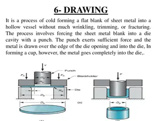
Module 2: Fastening devices and welding INTRODUCTION There are various types of fastening devices and the fastening of components is done by using different methods of welding. Various kinds of industrial applications use a variety and sizes of bolts, nuts and screws. In the engineering industry, a simplified method, also known as a conventional method, of drilled or tapped holes is used in a simplified representation. www.futuremanagers.com
Module 2: Fastening devices and welding (continued) THE CONVENTIONAL REPRESENTATION OF A DRILLED AND A TAPPED HOLE The represented angles for the drilled holes are illustrated: www.futuremanagers.com
Module 2: Fastening devices and welding (continued) THE APPROXIMATE PROPORTIONS USED FOR CONSTRUCTION Hexagonal bolt/nut = 1,5D (across the flats) Height of bolt head = 0,7D Height of nut = 0,8D Thread = 0,1D Thread before nut = 0,3D Thread after nut = 0,3D www.futuremanagers.com
Module 2: Fastening devices and welding (continued) THE CONVENTIONAL REPRESENTATION OF BOLTS, NUTS AND STUDS ASSEMBLY www.futuremanagers.com
Module 2: Fastening devices and welding (continued) THE THREADED ASSEMBLIES www.futuremanagers.com
Module 2: Fastening devices and welding (continued) THREADED FASTENERS Types of bolt heads: Types of machine screws: Square-head bolt; Round head; Tee-head bolt; Cheese-head; Cheese-head bolt; Countersunk head; Hook-head bolt. Socket head; Instrument head; Fillister-head. www.futuremanagers.com
Module 2: Fastening devices and welding (continued) LOCKING DEVICES Spring washers; Simmonds nut; Slotted nut; Castle nut; Tab washer; Lock nut. www.futuremanagers.com
Module 2: Fastening devices and welding (continued) KEYS AND KEYWAYS Rectangular and square keys; Gib head keys. www.futuremanagers.com
Module 2: Fastening devices and welding (continued) ELECTRICAL FITTINGS AND FASTENERS PVC conduit fittings and fasteners; Metal conduit fittings and fasteners. www.futuremanagers.com
Module 2: Fastening devices and welding (continued) WELDING Welds can be geometrically prepared in many different ways. The five basic types of weld joints are the butt joint, lap joint, corner joint, edge joint, and T- joint (a variant of this last is the cruciform joint). www.futuremanagers.com
Module 2: Fastening devices and welding (continued) WELDING PROCESSES The arc welding process creates and maintains an electric arc between an electrode and the base material to melt metals at the welding point. The most common gas welding process is oxy-fuel welding also known as oxyacetylene welding. Resistance welding involves the generation of heat by passing current through the resistance caused by the contact between two or more metal surfaces. www.futuremanagers.com
Module 2: Fastening devices and welding (continued) CLASSIFICATION OF WELDED JOINTS Butt joints: Corner joints: Lap joints: Edge joints: T-joints: www.futuremanagers.com
Module 2: Fastening devices and welding (continued) TYPICAL JOINT AND WELD TYPES Fillet: Square butt: Single Vee Butt: www.futuremanagers.com
Module 2: Fastening devices and welding (continued) WELDING TERMINOLOGY Welding symbol a combination of icons, figures and references to indicate the welding process, the position and required type of weld, the final finish and the dimensions. Reference line a horizontal on which the weld information is placed Arrow connects the reference line to the joint and points out the position of the weld. Other side the weld will be on the opposite side of the arrow head. www.futuremanagers.com
Module 2: Fastening devices and welding (continued) SUPPLEMENTARY SYMBOLS Weld all round: Weld on site: Finish: C chisel; F flame; G grinding; M machining. www.futuremanagers.com
Module 3: Screw Threads REPRESENTATION OF METRIC SCREW THREAD www.futuremanagers.com
Module 3: Screw Threads (continued) THE V-SHAPED SCREW THREAD The V-shaped screw thread is cut around a cylindrical external surface in a continuous helical groove shape to form the screw thread, which is also cut on an internal surface to form a screw thread. www.futuremanagers.com
Module 4: Machine Symbols BASIC MACHINE SYMBOLS The basic symbol used when a particular surface or texture is to be obtained by a process not involving the removal of material, for example etching, plating or pressing. www.futuremanagers.com
Module 4: Machine Symbols (continued) IDENTIFICATION AND CORRECT USE OF THE MAHINING SYMBOL This illustration represents surface texture obtained by material removal by machining operation: This illustration represents surface texture obtained by WITHOUT material removal by machining: www.futuremanagers.com
Module 4: Machine Symbols (continued) ROUGHNESS VALUES AND GRADE NUMBERS Roughness values Ra Roughness values Ra Roughness Micrometer Microinches Grade numbers 50 2,000 N12 25 1,000 N11 3,2 125 N8 0,4 16 N5 0,1 4 N3 0,025 1 N1 www.futuremanagers.com
Module 4: Machine Symbols (continued) APPLICATION OF MACHINING SYMBOLS INCLUDING ROUGHNESS VALUES Roughness value of 12,5 Roughness value of 12,5 be obtained with the removal of material: be obtained without the removal of material: www.futuremanagers.com
Module 4: Machine Symbols (continued) PRODUCTION METHOD, TREATMENT AND COATING a = Roughness value in micrometres b = Production method, treatment or coating c = Sampling length d = Direction lay e = Machining allowance f = Other roughness value than Ra www.futuremanagers.com
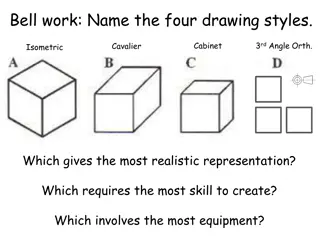
Module 5: First-angle orthographic projection INTRODUCTION Orthographic projection is a method of breaking three-dimensional (3D) drawings into two-dimensional views. Multiple two-dimensional (2D) views used during the manufacturing processes show the dimensions clearer than a single orientation three-dimensional views. www.futuremanagers.com
Module 5: First-angle orthographic projection (continued) PRINCIPAL OF FIRST-ANGLE ORTHOGRAPHIC PROJECTION Orthographic projection requires the projection of a three-dimensional object onto an imaginary plane, resulting in the creation of a two-dimensional shape. For orthographic projection, two principal planes are intersecting each other at 90 , namely the horizontal and vertical planes. The principal plane divides the space into four quadrants with each quadrant represented its angle of intersection. www.futuremanagers.com
Module 5: First-angle orthographic projection (continued) ANGLE OF ORTHOGRAPHIC PROJECTION In order to project the shape of an object onto a plane, it need to be placed within one of the four quadrants. In the case of first-angle orthographic projection, the object is placed in quadrant one. www.futuremanagers.com
Module 5: First-angle orthographic projection (continued) FIRST-ANGLE PROJECTION SYMBOL The projection symbol at the bottom of a drawing indicates that the drawing was drawn in first-angle orthographic projection. www.futuremanagers.com
Module 5: First-angle orthographic projection (continued) THE LAYOUT OF AN ENGINEERING DRAWING www.futuremanagers.com
Module 5: First-angle orthographic projection (continued) SECTIONAL DRAWING AND SECTIONAL VIEWS The function of a sectional view is to allow you to have a view of inside the object. Using sectional views can be very useful for parts that have a complex interior geometry. www.futuremanagers.com
Module 6: Isometric Drawing THE CONSTRUCTION OF AN ISOMETRIC CIRCLE Step 1: Construct a square with 40mm sides and mark the corners A,B,C,D. Step 2: Draw a straight line from corner B to corner D. Step 3: Find the centres of the sides of the square and mark them a,b,c,d. Step 4: Place the sharp point of the compass at corner A and draw an arc from point b to point c. Keep the compass at the same measurement and place the sharp point of the compass on point C of the square, draw an arc from point d to point a. Step 5: Draw a line from corner A to point c the middle of line CD, where line Ac crosses line BD mark that as point e. Draw a line from corner C to point a, the middle of line AB, where line Ca crosses line BD mark that as point f. Step 6: Place the sharp point of the compass at point e and draw an arc from point c to point d. Keep the compass at the same measurement and place the sharp point of the compass at point f and draw an arc from point a to point b. www.futuremanagers.com
Module 6: Isometric Drawing (continued) CIRCULAR ARCS OR RADII The construction for these arcs or radii is the same as for a full ellipse. The full ellipse will now not be drawn, but only the part or portion of the ellipse that is needed. www.futuremanagers.com
Module 7: Third-angle orthographic projection SECTIONING The same sectioning methods and procedures as in first-angle orthographic projection are applied. www.futuremanagers.com
Module 8: Interpenetration INTERSECTION OF TWO SQUARE PIPES www.futuremanagers.com
Module 8: Interpenetration (continued) INTERSECTION OF A HEXAGONAL PIPE WITH A SQUARE PIPE www.futuremanagers.com
Module 8: Interpenetration (continued) INTERSECTION OF A CYLINDER WITH A SQUARE PIPE www.futuremanagers.com
Module 8: Interpenetration (continued) INTERSECTION OF TWO CYLINDERS www.futuremanagers.com
Module 8: Interpenetration (continued) CURVES GENERATED BY MANUFACTURING PROCESSES The curve of interpenetration must be plotted once a detailed drawing is complete. T-ends, fork-ends and rad-ends are typical components where these curves are found. Plotting these curves of interpenetration are very similar to plotting the curves on prisms and pipes. www.futuremanagers.com
Module 8: Interpenetration (continued) CURVES OF INTERPENETRATION FOR T-ENDS www.futuremanagers.com


")
")

")
")
")
")
")
")
")
")
")
")
")
")
")
")

")

")
")
")
")

")
")
")
")
")

")


")
")
")
")
")