IEEE 802.11-17/0044r4: NDP Short Feedback Design Proposal
Proposal for a specific design in IEEE 802.11-17/0044r4 aimed at improving system and power efficiencies through a one-bit feedback mechanism. The design focuses on one Nss value and includes revisions for improved simulation results. The document outlines the need for efficient UL MU simultaneous scheduling and emphasizes low latency and reduced overhead for resource request feedback.

Download Presentation

Please find below an Image/Link to download the presentation.
The content on the website is provided AS IS for your information and personal use only. It may not be sold, licensed, or shared on other websites without obtaining consent from the author. Download presentation by click this link. If you encounter any issues during the download, it is possible that the publisher has removed the file from their server.
E N D
Presentation Transcript
May, 2017 doc.: IEEE 802.11-17/0044r4 NDP Short Feedback Design Date: 2017-05-02 Authors: Name Affiliations Address Phone email Leo Montreuil Broadcom Ron Porat Xiaogang Chen Broadcom Intel Qinghua Li Intel Submission Slide 1 Leo Montreuil, Broadcom, et. al.
May, 2017 doc.: IEEE 802.11-17/0044r4 Revision r4 Based on discussions and SP during the March meeting, this revision includes a proposal for one specific design as follows: One bit feedback only without high power mode One Nss value, Nss=2 This proposal seems to be the sweet spot between overhead, robustness and the maximum supportable number of users. We also revised the simulation results in Appendix A and added more simulation for CW interference in Appendix D. Submission Slide 2 Leo Montreuil, Broadcom, et. al.
May, 2017 doc.: IEEE 802.11-17/0044r4 Background (1) It is well accepted that being able to get a very short simultaneous feedback from a high number of STAs (all STAs) improve the 11ax system and power efficiencies [1], [3] Many feedbacks require 1 bit: PS-Poll (power efficiency), Channel Availability (collisions avoidance) A short simultaneous resource request feedback capable of supporting a high number of STAs is needed for an efficient UL MU simultaneous scheduling in addition to the existing (or enhanced) piggybacked buffer information Less overhead for resource request feedback than polling method Low and stable latency for resource request feedback, compared to possibly high and unpredictable latency with CSMA-CA in dense environments Submission Slide 3 Leo Montreuil, Broadcom, et. al.
May, 2017 doc.: IEEE 802.11-17/0044r4 Background (2) In Nov. 2016, added subclause 25.5.2.7 to the spec: 25.5.2.7 NDP feedback report procedure The NDP feedback report is a mechanism for an HE AP to collect short feedbacks from a very high number of HE STAs, in an efficient manner. The feedbacks (e.g. resource requests) are sent without data payloads in response to a Trigger frame. The feedbacks are not for channel sounding. This mechanism is optional for non-AP STA. But details of the NDP feedback mechanism are TBD and are needed to resolve several comments (e.g. 7390) This contribution propose a signaling technique for the NDP feedback mechanism that can handle a high number of STAs and is power and air time efficient Submission Slide 4 Leo Montreuil, Broadcom, et. al.
May, 2017 doc.: IEEE 802.11-17/0044r4 How to define the NDP feedback mechanism? UL MU transmission in response to a trigger frame Use frequency dimension for many small orthogonal allocations To avoid collisions, assign orthogonal allocations to users No data payload (NDP), STAs transmit energy on one orthogonal allocation for feedback with spreading gain in time domain for PHY robustness For minimal changes to the current PHY, we propose to use UL MU NDP simultaneous transmissions in response to a trigger frame; and define orthogonal allocations tone sets to multiplex different STAs feedbacks AP and STAs have a prior agreement on tone sets and P-matrix spreading to use for a given response (no collisions between STA) Submission Slide 5 Leo Montreuil, Broadcom, et. al.
May, 2017 doc.: IEEE 802.11-17/0044r4 Proposed signaling for Short Feedback (1 of 3) Define tone sets that spread a 242RU provides diversity and enables the AP to estimate AGC value based on HE-STF spread over a 242RU For compatibility with 20 MHz only STAs, to minimize degradation from DC offset and CFO, signaling use tones in each 20 MHz with indices: [-113:-6, 6:113] simple shifts to support 40/80MHz Puncture HE-LTF sequence except for tones at indices IULf 20 MHz tones used for UL feedback (up to 216 tones) - IULf 40 MHz tones used for UL feedback (up to 432 tones) IULf - 128, IULf + 128 80 MHz tones used for UL feedback (864 tones) IULf - 384, IULf - 128, IULf + 128, IULf + 384 80+80 MHz, 160 MHz tones used for UL feedback (up to 1728 tones) Same as 80 MHz on lower and upper 80 MHz Submission Slide 6 Leo Montreuil, Broadcom, et. al.
May, 2017 Proposed signaling for Short Feedback: IULf (2 of 3) doc.: IEEE 802.11-17/0044r4 Tone sets b = 1 b = 0 1 -113,-77,-41,6,42,78 -112,-76,-40,7,43,79 Complementary tone set are adjacent Noise like interference will add power in both bins, biasing RX decision toward a No Response instead of a 1 or 0 Non-coherent CW interference (not aligned to tone grid) will bias RX decision toward a No Response instead of a 1 or 0 2 -111,-75,-39,8,44,80 -110,-74,-38,9,45,81 3 -109,-73,-37,10,46,82 -108,-72,-36,11,47,83 4 -107,-71,-35,12,48,84 -106,-70,-34,13,49,85 5 -105,-69,-33,14,50,86 -104,-68,-32,15,51,87 6 -103,-67,-31,16,52,88 -102,-66,-30,17,53,89 7 -101,-65,-29,18,54,90 -100,-64,-28,19,55,91 8 -99,-63,-27,20,56,92 -98,-62,-26,21,57,93 9 -97,-61,-25,22,58,94 -96,-60,-24,23,59,95 10 -95,-59,-23,24,60,96 -94,-58,-22,25,61,97 11 -93,-57,-21,26,62,98 -92,-56,-20,27,63,99 12 -91,-55,-19,28,64,100 -90,-54,-18,29,65,101 Detection at RX does not need a Channel Estimate RX detect energy in one tone set and compare to energy in complementary tone set 13 -89,-53,-17,30,66,102 -88,-52,-16,31,67,103 14 -87,-51,-15,32,68,104 -86,-50,-14,33,69,105 15 -85,-49,-13,34,70,106 -84,-48,-12,35,71,107 16 -83,-47,-11,36,72,108 -82,-46,-10,37,73,109 17 -81,-45,-9,38,74,110 -80,-44,-8,39,75,111 18 -79,-43,-7,40,76,112 -78,-42,-6,41,77,113 Submission Slide 7 Leo Montreuil, Broadcom, et. al.
May, 2017 doc.: IEEE 802.11-17/0044r4 Proposed signaling for Short Feedback (3 of 3) In order to allow multiplexing of multiple users and/or improved robustness we repeat the punctured HE-LTF twice and multiply by the 2x2 P-matrix row corresponding to a specific spatial stream (SS) The maximum number of users supported per BW is: Bandwidth 20 MHz 40 MHz 80 MHz 160 MHz # Users 36 72 148 296 Submission Slide 8 Leo Montreuil, Broadcom, et. al.
May, 2017 doc.: IEEE 802.11-17/0044r4 Design Properties Channel estimation is not required for detection Detection performance is independent of sequence AP is not required to have prior knowledge of feedback sequence Signal is robust to interference and channel response Trivial detection, no adaptive threshold adjustment Compare sum of power between sets of complementary 6 tones Detection in unaffected by timing offset With the +/-400 ns timing accuracy and a 120 m radius, there is up to 1.6 us of timing offset. A No response from STA can be easily detected A No response from a STA could mean STA did not received the query, is out of range or the AP did not decode properly the feedback response. In interference prone environments, responses from STAs could be missed. AP can identify STAs with No response and treats them accordingly Submission Slide 9 Leo Montreuil, Broadcom, et. al.
May, 2017 doc.: IEEE 802.11-17/0044r4 Example of Detection Algorithm Processing for each P-matrix row: 1. De-spreading 2. Sum power per set of 6 tones 3. Compare powers between complementary tone sets for decision Detection algorithm for b0 (3 outcomes) P1 = sum(power in b0 = 1 tone locations) P0 = sum(power in b0 = 0 tone locations) ( P1 > K P0 ) ( P0 > K P1 ) not( P1 > K P0 ) & not( P0 > K P1 ) False: 1 is received as a 0 or 0 is received as a 1 Mis: 1 or 0 is received as a No Response For K=3, Probability of False is very low (<10-6) for SNR -2 dB For K=1, we only have two states. See Appendix A for simulation results b = 1 b = 0 No response Submission Slide 10 Leo Montreuil, Broadcom, et. al.
May, 2017 doc.: IEEE 802.11-17/0044r4 Summary We define an NDP short feedback report mechanism based on 18 tone sets per 20 MHz Users are multiplexed in the frequency and time using 2x2 P matrix. The design has the following attributes: Frequency spreading of tone set and complementary tone set are adjacent; makes the RX detection insensitive to the Channel frequency response Detection algorithm is independent of RX level, number of RX antennas and Sequence Detection is robust to interference Feedback response is an affirmative bn = 1 or bn = 0 For SNR -2 dB and 4 RX antenna, False detection is very low (< 10-6) 6 tones sequence PAPR is between 4.26 to 7.78 dB Median is 4.60 dB Submission Slide 11 Leo Montreuil, Broadcom, et. al.
May, 2017 doc.: IEEE 802.11-17/0044r4 References [1] IEEE 802.11-16/1367r0: NDP feedback report [2] IEEE 802.11-15/1334r1: HE-LTF sequence design [3] IEEE 11-16-0xxx-00-00ax-Proposed spec text for NDP feedback report Submission Slide 12 Leo Montreuil, Broadcom, et. al.
May, 2017 doc.: IEEE 802.11-17/0044r4 Straw poll #1 Do you agree to the NDP short feedback report as described in slides 6-8? Submission Slide 13 Leo Montreuil, Broadcom, et. al.
May, 2017 doc.: IEEE 802.11-17/0044r4 APPENDIX A SIMULATIONS RESULTS OVER VARIOUS CHANNELS, ANTENNA CONFIGURATION, CFO VALUES AND LOADING Submission Slide 14 Leo Montreuil, Broadcom, et. al.
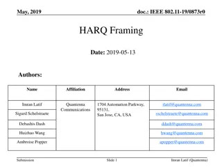
May, 2017 doc.: IEEE 802.11-17/0044r4 Flat channel, CFO=0, K=3, [1, 2, 4] RX Antennas, Nss=2 0 dB reference is power in 12 tones 0 10 Nb. of RX Antennas 1 or 0 from No Response Mis, 1 RX False, 1 RX Mis, 2 RX False, 2 RX Mis, 4 RX False, 4 RX -1 10 1 2.29e-2 -2 10 2 3.10e-3 -3 4 7.27e-5 10 -4 10 Probability -5 0 dB refers to noise power in 12 tones. SNR = -13.05 dB relative to 242 RU 10 -6 10 -7 10 -8 10 -9 10 -10 10 -6 -5 -4 -3 -2 -1 0 1 2 3 4 5 6 7 8 SNR (dB) Slide 15 Submission Leo Montreuil, Broadcom, et. al.
May, 2017 doc.: IEEE 802.11-17/0044r4 Multipath Channel, CFO = 0, K = 3, Nss = 2, 4 and 8 RX Antennas 0 dB reference is power in 12 tones 0 10 Mis, Ch. D 4RX Mis, Ch. E 4RX Mis, Ch. UMi-NLOS 4RX Mis, Ch. D 8RX Mis, Ch. E 8RX -1 10 -2 10 Probability -3 10 -4 10 -5 For 4 RX antennas and Ch. D, E and Umi-NLOS with SNR -2 dB Probability of False <= 10-6 10 -6 10 -2 -1 0 1 2 3 4 5 6 7 8 9 10 11 SNR (dB) Slide 16 Submission Leo Montreuil, Broadcom, et. al.
May, 2017 doc.: IEEE 802.11-17/0044r4 Simulations of 2 STA with CFO and power imbalance 1x1, 1x2 and 1x4 (TX antennas x RX antennas) Nss = 2 K=3 Channel D: SNR is for the ensemble of channel realizations Timing offset added +400 ns of timing error plus round trip delay for 100 m CFO and Power imbalance added RX antennas signals are equally combined Flat channel and MIS=10-2 : gain of 4 RX vs. 1 RX is 2 dB D channel and MIS=10-2 : gain of 4 RX vs. 1 RX is 4.6 dB Worst case analysis; STA #1 reply b0 = 1 and STA #2 reply b0 = 0 Select tone locations that maximize crosstalk b0 = 1 Energy on tones set: [-113,-77,-41,6,42,78] b0 = 0 Energy on tones set: [-112,-76,-40,7,43,79] Submission Slide 17 Leo Montreuil, Broadcom, et. al.
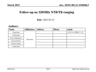
May, 2017 doc.: IEEE 802.11-17/0044r4 Cont. - STA #1 Probability Mis & False 0 dB reference is power in 12 tones 0 10 Mis, 1 RX False, 1 RX Mis, 2 RX False, 2 RX Mis, 4 RX False, 4 RX -1 10 -2 10 Probability -3 10 -4 10 AP: 1, 2 and 4 RX antennas CP: 1.6 us, Time offset: 1.0667 us #1 send b0 = 1, #2 send b0 = 0 #1 to #2 power: [0, +9] dB #1 to #2 CFO: [-350, +350] Hz -5 10 False for 4 RX antennas is not measurable for SNR -2 dB -6 10 -2 -1 0 1 2 3 4 5 6 7 8 9 10 11 12 SNR (dB) Slide 18 Submission Leo Montreuil, Broadcom, et. al.
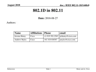
May, 2017 doc.: IEEE 802.11-17/0044r4 Simulation of a Loaded System 18 users (all tones are occupied) with 20 dB power imbalance Flat channel Nss = 2 (2 symbols transmitted), users use first row of P-Matrix 1 RX antenna and each user has 1 TX antenna Detection using K = 3 Simulation #1 b = 1 on tone set [9], P = 0 dB, CFO = 350 Hz b = 0 on tone set [1 3 5 7 11 13 15 17], P = 20 dB, CFO = -350 Hz b = 0 on tone set [2 4 6 8 10 12 14 16 18], P = 20 dB, CFO = 350 Hz Simulation #2 b = 1 on tone set [9], P = 0 dB, CFO = 1 KHz b = 0 on tone set [1 3 5 7 11 13 15 17], P = 20 dB, CFO = -1 KHz b = 0 on tone set [2 4 6 8 10 12 14 16 18], P = 20 dB, CFO = 1 KHz Simulation #3 b = 1 on tone set [9], P = 0 dB, CFO = 4 KHz b = 0 on tone set [1 3 5 7 11 13 15 17], P = 20 dB, CFO = -4 KHz b = 0 on tone set [2 4 6 8 10 12 14 16 18], P = 20 dB, CFO = 4 KHz Submission Slide 19 Leo Montreuil, Broadcom, et. al.
May, 2017 doc.: IEEE 802.11-17/0044r4 Cont. Probability for user on tone set 9 0 10 Mis: 350 KHz Mis: 1 KHz Mis: 4 KHz False: 4 KHz -1 10 -2 10 Probability -3 10 0 dB reference is power in 12 tones -4 10 -4 -3 -2 -1 0 1 2 3 4 5 6 7 8 9 SNR (dB) Slide 20 Submission Leo Montreuil, Broadcom, et. al.
May, 2017 doc.: IEEE 802.11-17/0044r4 Simulation Summary Degradation is negligible if CFO 1 KHz and power imbalance 20 dB, irrespective of Channel response 18 users with +20 dB power imbalance and CFO = 350 Hz and 1000 Hz (slide #20) has same probability as 1 user with CFO = 0 Hz (slide #15) 2 users with +9 dB power imbalance and CFO = 350 Hz Channel D, 4 RX antennas (slide #18) has same probability as 1 user with CFO = 0 Hz, Channel D, 4 RX antennas (slide #16) At MIS = 10-2 , Gain for 4 RX combining vs. 1 RX antenna: Flat channel : 2.0 dB D channel : 4.6 dB UMi-NLOS channel : 4.9 dB No measurable error floor for Flat, D, E and UMi-NLOS channel Submission Slide 21 Leo Montreuil, Broadcom, et. al.
May, 2017 doc.: IEEE 802.11-17/0044r4 APPENDIX - B Submission Slide 22 Leo Montreuil, Broadcom, et. al.
May, 2017 doc.: IEEE 802.11-17/0044r4 Tones alignment between 20 MHz only STAs and 40/80 MHz STAs Four 20 MHz only STAs 80 MHz Tones at [-116:-2, 2:116] are common to 20 MHz only, 40 and 80 MHz tone plan 40 MHz Submission Slide 23 Leo Montreuil, Broadcom, et. al.
May, 2017 doc.: IEEE 802.11-17/0044r4 APPENDIX - C Submission Slide 24 Leo Montreuil, Broadcom, et. al.
May, 2017 doc.: IEEE 802.11-17/0044r4 Comparison of Proposed Schemes We compare the proposed scheme which we name in the plots M- OOK (Manchester OOK) with an alternative scheme which we call D- BPSK In the D-BPSK all 12 tones are populated, for example for tone set 1 b0 = 1 Tones locations: -113,-77,-41,6,42,78 are modulated with +1 b0 = 1 Tones locations: -112,-76,-40,7,43,79 are modulated with +1 b0 = 0 Tones locations: -113,-77,-41,6,42,78 are modulated with +1 b0 = 0 Tones locations: -112,-76,-40,7,43,79 are modulated with -1 The receiver multiplies adjacent tones by the conjugates to create a decoding metric: sum(Y(k)conj(Y(k+1)))>0 Under ideal conditions both schemes perform the same In practice D-BPSK suffers from: Timing errors Interference will bias the decision towards an error Not easy to detect a No Response Error floor at around 10-3 in UMi-NLOS Channel Submission Slide 25 Leo Montreuil, Broadcom, et. al.
May, 2017 doc.: IEEE 802.11-17/0044r4 Flat Channel, 1 TX, 1 RX, Nss=2 0 dB reference is power in 12 tones 0 10 False: M-OOK K=1, 1.6us False: D-BPSK, 0us False: D-BPSK, 0.8 us False: D-BPSK, 1.6 us False: D-BPSK, 2.4 us -1 10 -2 10 Probability -3 10 -4 10 -5 10 -6 10 -4 -3 -2 -1 0 1 2 3 4 5 6 7 8 9 SNR (dB) Slide 26 Submission Leo Montreuil, Broadcom, et. al.
May, 2017 doc.: IEEE 802.11-17/0044r4 Channel D, 1 TX, 1 RX, Nss=2 0 dB reference is power in 12 tones 0 10 False: D-BPSK, 1.6us False: M-OOK K=1, 1.6us Mis: M-OOK K=3, 1.6us -1 10 -2 10 Probability -3 10 -4 10 -5 10 -6 10 -4 -3 -2 -1 0 1 2 3 4 5 6 7 8 9 10 SNR (dB) Slide 27 Submission Leo Montreuil, Broadcom, et. al.
May, 2017 Channel UMi-NLOS, 1 TX, 1 RX, Nss=2 doc.: IEEE 802.11-17/0044r4 0 dB reference is power in 12 tones 0 10 False: D-BPSK, 1.6us False: M-OOK K=1, 1.6us Mis: M-OOK K=3, 1.6us -1 10 -2 10 Probability -3 10 -4 10 -5 10 -6 10 0 1 2 3 4 5 6 7 8 9 10 11 12 13 14 SNR (dB) Slide 28 Submission Leo Montreuil, Broadcom, et. al.
May, 2017 D-BPSK and M-OOK K=1 signals distance doc.: IEEE 802.11-17/0044r4 Adjacent tones are orthogonal Use a 2-D diagram to calculate distance Assumption: GI time > Timing offset Tone #1 D-BPSK +1 D-BPSK (tone #1 is phase reference, tone #2 carries the information): b=1 +1 on tone #1 and +1 on tone #2 b=0 +1 on tone #1 and -1 on tone #2 -1 +1 Tone #2 D=2 x>0 M-BPSK (send energy on tone #1 or #2): b=1 2 on tone #1 and 0 on tone #2 b=0 0 on tone #1 and 2 on tone #2 M-OOK 2 2 0 In flat channel and timing offset = 0, performance of D-BPSK and M-OOK K=1 are identical Submission Slide 29 Leo Montreuil, Broadcom, et. al.
May, 2017 doc.: IEEE 802.11-17/0044r4 APPENDIX D CW INTERFERENCE Submission Slide 30 Leo Montreuil, Broadcom, et. al.
May, 2017 doc.: IEEE 802.11-17/0044r4 CW Interference Simulations Use tone set #12 -91,-55,-19,28,64,100 -90,-54,-18,29,65,101 On tone set #12 P-Matrix row #1, User 1 send b1 On tone set #12 P-Matrix row #2, User 2 send b2 Power in 12 tones is 1 for each User GI = 3.2 us Detector scaling factor K=3 Find worst case frequency by sweeping CW from tone 61 to 68, increase Interference level to get Mis and False detection Simple receiver as described on slide 10 Submission Slide 31 Leo Montreuil, Broadcom, et. al.
May, 2017 doc.: IEEE 802.11-17/0044r4 Signal/Interference (S/I) for Mis and False with CW at worst Frequency False S/I (dB) S/I -8.60 S/I -7.78 S/I -8.60 S/I -8.72 S/I -9.36 S/I -7.78 S/I -8.60 - Signals Mis S/I (dB) OK (dB) -8.60 < S/I < +1.17 -7.78 < S/I < +1.77 -8.60 < S/I < +1.18 -8.72 < S/I < +1.13 -9.36 < S/I < +0.24 -7.78 < S/I < +1.77 -8.60 < S/I < +1.17 - +1.17 S/I +1.77 S/I +1.18 S/I +1.13 S/I +0.24 S/I +1.77 S/I +1.17 S/I - b1 = 1, b2 = 0 b1 = 1, b2 = 1 b1 = 0, b2 = 0 b1 = 1, b2 = NoResp b1 : signal on first row of P-Matrix, b2 : signal on second row of P-Matrix Submission Slide 32 Leo Montreuil, Broadcom, et. al.
May, 2017 doc.: IEEE 802.11-17/0044r4 CW Interference with Erasure From 6 tones set and complementary 6 tones set, remove the largest magnitude tones from both sets This can be done on each antenna separately Remaining two 5 tones set power are summed for decision Erasure circuitry can be left ON all the time minor impact on overall performance Improve robustness in presence of narrowband interference Submission Slide 33 Leo Montreuil, Broadcom, et. al.
May, 2017 Simulations with CW Interference Erasure Technique doc.: IEEE 802.11-17/0044r4 Send b1=1 or b1=0 on tone set #12 Energy on tones: [-91,-55,-19,28,64,100] or [-90,-54,-18,29,65,101] Flat channel, CFO = 0, 1 RX antenna, GI = 3.2 us Send a time-domain CW interference at +20 dB relative to power in 12 tones S/I = -20 dB CW frequencies used to check effectiveness of interference erasure: No CW: No CW interference (baseline reference) CW1: 5.0370625 MHz @ +20 dB (between tones 64 & 65) CW2: 5.0781250 MHz @ +20 dB (on top of tones 65) CW3: 5.1171875 MHz @ +20 dB (between tones 65 & 66) CW4: 5.0000000 MHz @ +20 dB (on top of tones 64) CW5: 4.9609390 MHz @ +20 dB (between tones 63 & 64) RX does not know the frequency or magnitude of CW interference Submission Slide 34 Leo Montreuil, Broadcom, et. al.
May, 2017 Simulations with CW Interference Erasure Technique, S/I = -20 dB, b1 = 1 doc.: IEEE 802.11-17/0044r4 0 10 MIS: no CW FALSE: no CW MIS: CW1 FALSE: CW1 MIS: CW2 FALSE: CW2 MIS: CW3 FALSE: CW3 -1 10 -2 10 Probability -3 10 -4 10 -5 10 -6 10 -3 -2 -1 0 1 2 3 4 5 6 7 SNR (dB) Slide 35 Submission Leo Montreuil, Broadcom, et. al.
May, 2017 Simulations with CW Interference Erasure Technique, S/I = -20 dB, b1 = 0 doc.: IEEE 802.11-17/0044r4 0 10 MIS: no CW FALSE: no CW MIS: CW1 FALSE: CW1 MIS: CW4 FALSE: CW4 MIS: CW5 FALSE: CW5 -1 10 -2 10 Probability -3 10 -4 10 -5 10 -6 10 -3 -2 -1 0 1 2 3 4 5 6 7 SNR (dB) Slide 36 Submission Leo Montreuil, Broadcom, et. al.
May, 2017 doc.: IEEE 802.11-17/0044r4 Results Summary of CW Interference Erasure Technique, S/I = 20 dB Degradation estimated by increasing signal level until MIS = 10-2 Erasure OFF Erasure ON b1 = 1 Interference RX Decision Degradation RX Decision Degradation None 0 dB (reference) -0.4 dB 1 1 CW1 NoRes (Mis) +20.7 dB +0.9 dB 1 CW2 +22.3 dB +0.9 dB 0 (False) 1 CW3 +13.0 dB +0.7 dB 0 (False) 1 Erasure OFF Erasure ON b1 = 0 Interference RX Decision Degradation RX Decision Degradation None 0 dB (reference) -0.4 dB 0 0 CW1 NoRes (Mis) +19.0 dB +1.2 dB 0 CW4 0 dB -0.4 dB 0 0 CW5 +21.1 dB +0.8 dB 1 (False) 0 Submission Slide 37 Leo Montreuil, Broadcom, et. al.