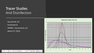
Tracer Study at City of Fairfield Public Works Waterman WTP - Ozone Contact Basin

Tracer study conducted at City of Fairfield Public Works Waterman Water Treatment Plant focused on the Ozone Contactor Basin, involving the injection of fluoride as a tracer, monitoring flow rates, and analyzing tracer concentrations over specific time intervals. The study aimed to assess the efficiency of the treatment process in the plant.

Download Presentation

Please find below an Image/Link to download the presentation.
The content on the website is provided AS IS for your information and personal use only. It may not be sold, licensed, or shared on other websites without obtaining consent from the author. Download presentation by click this link. If you encounter any issues during the download, it is possible that the publisher has removed the file from their server.
E N D
Presentation Transcript
City of Fairfield Public Works Waterman WTP CA4810003 Tracer Study Ozone Contactor Basin 3 July 23, 2021 Tracer Input Ozone Sample Pt. Tracer Study Drinking Water Treatment Plant Type: Actifloc Reactor: Ozone Contactor Basin Basin Volume: 36,420 gallons Tracer Input Pipe Sample Pt. Volume: 27,500 gallons Tracer Method: Slug-Dose Tracer: Fluoride (liquid) Mass Added: 232 grams Mass Recovered: 214 grams Percent Mass Recovered: 92% Test Flow: 6 MGD Baffling Factor at Sample Pt: 0.74 Ozone Sample Pt. L:W = 13 Performed by: Guy Schott Stuart Hamilton and Staff Water Depth @ No Flow: 19.25 ft Water Depth @ 11.25 mgd: 19.88 ft Basin Water Volume @ 11.25 mgd: 36,420 gal ~27,500 gallons to sample point Ozone Diffusers
Tracer Input Ozone Sample Pt. Tracer Input Pipe Ozone Sample Pt. L:W = 13 Water Depth @ No Flow: 19.25 ft Water Depth @ 11.25 mgd: 19.88 ft Basin Water Volume @ 11.25 mgd: 36,420 gal ~27,500 gallons to sample point Ozone Diffusers
Tracer Injection Slug Dose Before start of tracer test, 1,000 mL of Hydrofluosilicic acid (~232 grams F) was added to a closed valve calibrated cylinder as shown in the photo. At the start of the test, the outlet valve is manually opened that allow the fluoride to flow down the injection line into the ozone feed water. High pressure water hose is then opened to complete flushing of line.
Sample Station Bottom of Cell 4 Sample frequency ranged from 15 to 40 second intervals: Samples 1 6: 20 seconds Samples 6 36: 15 seconds Samples 36 41: 20 seconds Samples 41 46: 30 seconds Samples 46 50: 40 seconds
Monitoring - Station 1 7/27/2021 Date: System Name: City of Fairfield Tracer Study: Flow Rate/Basin: Ozone Contactor 4,167 27,500 6.60 396 15 Tracer Ion: Fluoride H2SiF6 chemical (%): 24.07 Available Fluoride Ion, %: 19.04 Specific Gravity: 1.23 H2SiF6 weight: 10.25451 gpm gallons minutes seconds 0.038 6.00 MGD Liters of H2SiF6 inputted: Mass Added (grams): Oz of H2SiF6 inputted: Liters added: 1.000 234.2 33.81 0.3 gal Basin Volume: HRT: HRT: Precision (sec): lb/gal 1.000 Elasped Time, sec Elasped Time, Min:Sec Sample Interval, seconds Tracer Conc., mg/L Tracer Conc., (-) BG mg/L Elasped Time, Min:Sec Elasped Time, Min:Sec Sample Interval, seconds Tracer Conc., mg/L Tracer Conc., (-) BG mg/L Sample # t/T Sample # t/T 1 0 00 min 00 sec 0 0.000 0.1040 0.000 26 400 06 min 40 sec 15 1.010 1.700 1.595 2 20 00 min 20 sec 20 0.051 0.1060 0.000 27 415 06 min 55 sec 15 1.048 2.080 1.975 3 40 00 min 40 sec 20 0.101 0.1050 0.000 28 430 07 min 10 sec 15 1.086 1.930 1.825 4 60 01 min 00 sec 20 0.152 0.1040 0.000 29 445 07 min 25 sec 15 1.124 1.990 1.885 5 80 01 min 20 sec 20 0.202 0.1130 0.000 30 460 07 min 40 sec 15 1.162 1.990 1.885 6 100 01 min 40 sec 20 0.253 0.1040 0.000 31 475 07 min 55 sec 15 1.200 1.97 1.865 7 115 01 min 55 sec 15 0.290 0.1030 0.000 32 490 08 min 10 sec 15 1.237 1.79 1.685 8 130 02 min 10 sec 15 0.328 0.1020 0.000 33 505 08 min 25 sec 15 1.275 1.88 1.775 9 145 02 min 25 sec 15 0.366 0.1050 0.000 34 520 08 min 40 sec 15 1.313 1.67 1.565 10 160 02 min 40 sec 15 0.404 0.1030 0.000 35 535 08 min 55 sec 15 1.351 1.8300 1.725 11 175 02 min 55 sec 15 0.442 0.2130 0.108 36 550 09 min 10 sec 15 1.389 1.6600 1.555 12 190 03 min 10 sec 15 0.480 0.3580 0.253 37 570 09 min 30 sec 20 1.440 1.6800 1.575 13 205 03 min 25 sec 15 0.518 0.1120 0.007 38 590 09 min 50 sec 20 1.490 1.6100 1.505 14 220 03 min 40 sec 15 0.556 0.1970 0.092 39 610 10 min 10 sec 20 1.541 1.7000 1.595 15 235 03 min 55 sec 15 0.593 1.0100 0.905 40 630 10 min 30 sec 20 1.591 1.0900 0.985 16 250 04 min 10 sec 15 0.631 1.0400 0.935 41 650 10 min 50 sec 20 1.642 0.8080 0.703 17 265 04 min 25 sec 15 0.669 0.5130 0.408 42 680 11 min 20 sec 30 1.717 1.2700 1.165 18 280 04 min 40 sec 15 0.707 1.060 0.955 43 710 11 min 50 sec 30 1.793 1.2000 1.095 19 295 04 min 55 sec 15 0.745 2.020 1.915 44 740 12 min 20 sec 30 1.869 0.6340 0.529 20 310 05 min 10 sec 15 0.783 1.590 1.485 45 770 12 min 50 sec 30 1.945 0.6740 0.569 21 325 05 min 25 sec 15 0.821 1.480 1.375 46 800 13 min 20 sec 30 2.020 0.4870 0.382 22 340 05 min 40 sec 15 0.859 1.690 1.585 47 840 14 min 00 sec 40 2.121 0.4670 0.362 23 355 05 min 55 sec 15 0.897 1.620 1.515 48 880 14 min 40 sec 40 2.222 0.6030 0.498 24 370 06 min 10 sec 15 0.934 1.810 1.705 49 920 15 min 20 sec 40 2.323 0.4780 0.373 25 385 06 min 25 sec 15 0.972 1.670 1.565 50 960 16 min 00 sec 40 2.424 0.4110 0.306
Main Menu Slug-Dose Method - 1 Test Date: 23-Jul-21 27,500 27,500 Treatment Plant/Reactor: City of Fairfield Reactor Operating Volume: Reactor Volume per foot: gallons (avg) gal/ft Dispersion Concentration: % Mass Recovery: 2.05 92.0% mg/L (calc) Tracer Ion: Fluoride 232.00 Mass Added (Co): Constant Volume Reactors: grams Pipeline Volume: Other Volume: 0 0 gallons gallons MGD Mass Recovered (Co): Tracer Background: 213.54 0.1060 grams mg/L 0.470 1.000 33.814 LBS Liters ounces 6.000 Elapsed Time, (t) min Sample Interval, min. Reactor Water Level, ft Reactor Flow, gpm Operating Volume Gallons Weighted Avg Residence Time ( ), min Normalized Time t/ Measured Tracer, mg/L Adjusted Concentration, mg/L Mass of Recovered, (C*dt*Q), mg Cumulative Mass of Recovered, mg Sample # Normalized F-Curve 1 2 3 4 5 6 7 8 9 10 11 12 13 14 15 16 17 18 19 20 21 22 23 24 25 26 27 28 29 30 31 32 33 34 35 36 37 38 39 40 41 42 43 44 45 46 47 48 49 50 0.0 0.333 0.667 1.001 1.335 1.669 1.917 2.167 2.417 2.667 2.917 3.167 3.417 3.667 3.917 4.167 4.417 4.667 4.917 5.167 5.417 5.667 5.917 6.167 6.417 6.667 6.917 7.167 7.417 7.667 7.917 8.167 8.417 8.667 8.917 9.167 9.500 9.833 10.166 10.499 10.832 11.333 11.833 12.333 12.833 13.333 14.000 14.667 15.334 16.001 0 1.00 1.00 1.00 1.00 1.00 1.00 1.00 1.00 1.00 1.00 1.00 1.00 1.00 1.00 1.00 1.00 1.00 1.00 1.00 1.00 1.00 1.00 1.00 1.00 1.00 1.00 1.00 1.00 1.00 1.00 1.00 1.00 1.00 1.00 1.00 1.00 1.00 1.00 1.00 1.00 1.00 1.00 1.00 1.00 1.00 1.00 1.00 1.00 1.00 1.00 4,167 4,167 4,167 4,167 4,167 4,167 4,167 4,167 4,167 4,167 4,167 4,167 4,167 4,167 4,167 4,167 4,167 4,167 4,167 4,167 4,167 4,167 4,167 4,167 4,167 4,167 4,167 4,167 4,167 4,167 4,167 4,167 4,167 4,167 4,167 4,167 4,167 4,167 4,167 4,167 4,167 4,167 4,167 4,167 4,167 4,167 4,167 4,167 4,167 4,167 - 0 0.00 0.05 0.10 0.15 0.20 0.25 0.29 0.33 0.37 0.40 0.44 0.48 0.52 0.556 0.594 0.63 0.67 0.707 0.745 0.783 0.821 0.86 0.90 0.93 0.97 1.01 1.05 1.09 1.12 1.16 1.20 1.24 1.28 1.31 1.35 1.39 1.44 1.49 1.54 1.59 1.64 1.72 1.79 1.87 1.94 2.02 2.12 2.22 2.32 2.42 0.0000 0.0000 0.0000 0.0000 0.0000 0.0000 0.0000 0.0000 0.0000 0.00 0.11 0.25 0.01 0.09 0.90 0.93 0.41 0.95 1.91 1.48 1.37 1.58 1.51 1.70 1.56 1.59 1.97 1.82 1.88 1.88 1.86 1.68 1.77 1.56 1.72 1.55 1.57 1.50 1.59 0.98 0.70 1.16 1.09 0.53 0.57 0.38 0.36 0.50 0.37 0.31 0.00 0.00 0.00 0.00 0.00 0.00 0.00 0.00 0.00 0.00 421.90 993.64 23.66 358.82 3,564.49 3,682.78 1,604.81 3,761.64 7,546.95 5,851.45 5,417.71 6,245.75 5,969.74 6,718.91 6,166.89 6,285.18 7,783.53 7,192.08 7,428.66 7,428.66 7,349.80 6,640.05 6,994.92 6,166.89 6,797.77 6,127.46 8,266.82 7,899.17 8,371.86 5,168.07 3,686.98 9,197.72 8,627.34 4,163.83 4,479.27 3,004.58 3,797.72 5,228.43 3,913.44 3,208.60 0.0 0.0 0.0 0.0 0.0 0.0 0.0 0.0 0.0 0.0 421.9 1,415.5 1,439.2 1,798.0 5,362.5 9,045.3 10,650.1 14,411.8 21,958.7 27,810.1 33,227.9 39,473.6 45,443.3 52,162.3 58,329.2 64,614.3 72,397.9 79,589.9 87,018.6 94,447.2 101,797.0 108,437.1 115,432.0 121,598.9 128,396.7 134,524.1 142,791.0 150,690.1 159,062.0 164,230.1 167,917.0 177,114.8 185,742.1 189,905.9 194,385.2 197,389.8 201,187.5 206,415.9 210,329.4 213,538.0 0.00 0.00 0.00 0.00 0.00 0.00 0.00 0.00 0.00 0.00 0.00 0.01 0.01 0.008 0.025 0.04 0.05 0.067 0.103 0.130 0.16 0.18 0.21 0.24 0.27 0.30 0.34 0.37 0.41 0.44 0.48 0.51 0.54 0.57 0.60 0.63 0.67 0.71 0.74 0.77 0.79 0.83 0.87 0.89 0.91 0.92 0.94 0.97 0.98 1.00 0.1040 0.1060 0.1050 0.1040 0.1130 0.1040 0.1030 0.1020 0.1050 0.1030 0.2130 0.3580 0.1120 0.1970 1.0100 1.0400 0.5130 1.060 2.020 1.590 1.480 1.690 1.620 1.810 1.670 1.700 2.080 1.930 1.990 1.990 1.97 1.79 1.88 1.67 1.8300 1.6600 1.6800 1.6100 1.7000 1.0900 0.8080 1.2700 1.2000 0.6340 0.6740 0.4870 0.4670 0.6030 0.4780 0.4110 0.3 0.3 0.3 0.3 0.3 0.2 0.3 0.3 0.3 0.3 0.3 0.3 0.3 0.3 0.3 0.3 0.3 0.3 0.3 0.3 0.3 0.3 0.3 0.3 0.3 0.3 0.3 0.2 0.3 0.3 0.2 0.3 0.3 0.3 0.3 0.3 0.3 0.3 0.3 0.3 0.5 0.5 0.5 0.5 0.5 0.7 0.7 0.7 0.7 27,500 27,500 27,500 27,500 27,500 27,500 27,500 27,500 27,500 27,500 27,500 27,500 27,500 27,500 27,500 27,500 27,500 27,500 27,500 27,500 27,500 27,500 27,500 27,500 27,500 27,500 27,500 27,500 27,500 27,500 27,500 27,500 27,500 27,500 27,500 27,500 27,500 27,500 27,500 27,500 27,500 27,500 27,500 27,500 27,500 27,500 27,500 27,500 27,500 6.6 6.6 6.6 6.6 6.6 6.6 6.6 6.6 6.6 6.6 6.6 6.6 6.6 6.6 6.6 6.6 6.6 6.6 6.6 6.6 6.6 6.6 6.6 6.6 6.6 6.6 6.6 6.6 6.6 6.6 6.6 6.6 6.6 6.6 6.6 6.6 6.6 6.6 6.6 6.6 6.6 6.6 6.6 6.6 6.6 6.6 6.6 6.6 6.6
To determine the hydraulic efficiency or disinfectant exposure time of water through one or more reactors. The addition of known quantities of a nonreactive chemical (tracer) is added in the form of a pulse (slug) or step-input. The time of travel or disinfectant exposure time through the reactor is related to: Flow rate Reactor water volume Water Depth Reactor configuration Purpose of a Tracer Study
C is the disinfectant residual (mg/L) at the point of inactivation compliance. Disinfection Exposure Time of Fluid in Vessel for Determining Ct10 The disinfection exposure time of water used for Ct10 calculation is the time (t10) it takes for 10 percent of the water entering the reactor to exit the reactor. To determine this, a marker (nonreactive tracer) is introduced into the water and is monitored leaving the reactor. Example: 1,000 grams of tracer is slug-dose; t10 is that time when 100 grams of tracer material (10%) has exit the reactor.
- Log inactivation is based on the Delivered Dose, Ct10 C is the disinfectant residual (mg/L) t10 is the exposure or contact time (minutes) Multiply them: Ct Ct10 10 Value Value C t10= mg/L min (delivered dose) The calculated Ct10 value is looked up in EPA Cttables to determine the log inactivation based on specific monitoring parameters (pH, disinfectant residual and/or temperature).
Baffling factor or short-circuiting factor: Determined from tracer study or estimated BF = t10/ HRT from tracer study HRT (hydraulic residence time) = reactor volume divided by reactor flow Once the BF is determined, then it is applied to the operations of the reactor for determining the disinfectant exposure time. Example: Baffling Factor (BF) Ozone reactor operating volume: 27,500 gallons Exit flow: 5,000 gpm (7.2 MGD) BF: 0.74, from tracer study Calculated contact or disinfection exposure time: 27,500 gal 5,000 gpm 0.74 = 5.5 minutes = t10
Slug-Dose or Pulse-Input Method Adding the entire amount of tracer at the beginning of test. The reactor outlet tracer concentration is monitored up to 3 HRT to determine mass recovery and the time (t10) it takes for 10% of the tracer mass to exit the reactor. Test Method
Method of Analysis and Equipment Intellical ISEF121 Fluoride (F-) Ion Selective Electrode (ISE) HQ40d Portable ISE Multi-Parameter Meter Fluoride Ionic Strength Adjustor (ISA) Fluoride Standards (0.2/2.0 & 0.5/ 5.0 mg/L) 25 mL graduated cylinder Finnpipette F2 variable volume pipette, capacity 0.5 - 5 mL Electrode stirrer stand 50 mL beakers Stir Bar, Magnetic, Polygon
Contact Guy Schott, P.E. State Water Resources Control Board Division of Drinking Water Santa Rosa, CA Guy.Schott@waterboards.ca.gov 707-576-2732


 at the point of")