Optimizing Time-Stamp Reporting for 802.11 FTM Measurements
The document discusses issues with the current time-stamp reporting in IEEE 802.11 FTM measurements, focusing on reducing signaling overhead by optimizing the number of bits used in time-stamp representation. Suggestions include reducing the resolution and maximum value of time stamps to save signaling bits. It also addresses ranging ambiguities in TB, non-TB, and Passive TB Ranging scenarios. The author, Erik Lindskog, proposes adjustments to improve efficiency in time-stamp reporting for various ranging operations.

Download Presentation

Please find below an Image/Link to download the presentation.
The content on the website is provided AS IS for your information and personal use only. It may not be sold, licensed, or shared on other websites without obtaining consent from the author. Download presentation by click this link. If you encounter any issues during the download, it is possible that the publisher has removed the file from their server.
E N D
Presentation Transcript
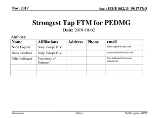
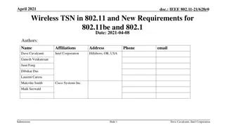
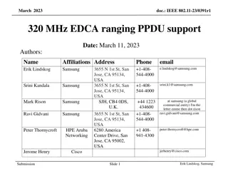
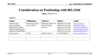
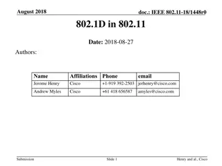
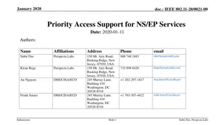
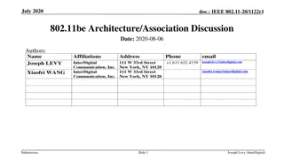
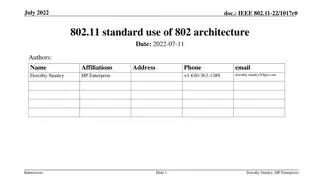
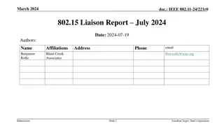
Sept 2020 doc.: IEEE 802.11-20/1555r0 Wi-Fi FTM Timestamp Optimization Date: 2020-09-30 Authors: Name Erik Lindskog Affiliations Address Samsung Phone email e.lindskog@samsung.com 3655 N 1st St, San Jose, CA 95134, USA Erik Lindskog, Samsung Submission Slide 1
Sept 2020 doc.: IEEE 802.11-20/1555r0 Issues with current time-stamp reporting The current time-stamp reporting for 802.11 FTM measurements is not highly optimized. We can reduce the signaling overhead in the ranging by optimizing the number of bits used in the reporting of the time-stamps. For Passive TB Ranging it is extra important to use the minimum required number of bits for conveying the time stamps as the time- stamps (and their error measures) are transmitted in broadcast frames likely at somewhat low MCS levels and may thus occupy many OFDM symbols. Again, this is especially the case for Passive TB Ranging as here the ISTAs are not limited to reporting only the TOA of the NDPs they receive from the RSTA but may, and it is desired, report the TOAs on the NDPs they receive from the other ISTAs that participate in the Passive TB Ranging operation in question. Still, also for TB and non-TB Ranging, optimizing the time-stamp reporting has value. Erik Lindskog Submission Slide 2
Sept 2020 doc.: IEEE 802.11-20/1555r0 Time-stamp Resolution In the current 802.11az draft [1], the FTM time stamps use 48 bits to represent the time-stamp in units of 1 picosecond. However, we don t really need all these bits. In the sub 7GHz applications, the current max bandwidth is 160 MHz. Even if the bandwidth is expanded to the 320 MHz that is being considered in 802.11be, it is probably safe to assume that a resolution of, say, 128 ps, corresponding to a propagation distance of 3.84 cm, is high enough resolution. This argument applies to TB, non-TB and Passive TB Ranging. Thus, by reducing the resolution in the reported time stamps we can save bits in the signaling. Erik Lindskog Submission Slide 3
Sept 2020 doc.: IEEE 802.11-20/1555r0 Time-stamp Max Value In the current 802.11az draft [1], the FTM time stamps use 48 bits to represent the time-stamp in units of 1 picosecond and therefore covers the range from 0 to about 218 seconds. This corresponds to a propagation distance of about 84 million km. This large max value is not really necessary. By reducing the max value of the reported time-stamps we can save bits in the signaling. Erik Lindskog Submission Slide 4
Sept 2020 doc.: IEEE 802.11-20/1555r0 Ranging Ambiguities High level Let us assume that the max value of each reported time-stamp is T_timestamp_max. For TB and Non-Tb Ranging, the calculated range depends on the reported time-stamps divided by 2, see [2]. Thus the calculated range time will have an ambiguity of c*T_timestamp_max/2. Correspondingly, when in Passive TB Ranging calculating the differential distance from a PSTA to two anchor stations (ISTAs/RSTA), the differential distance depends on the reported time-stamps divided by 2, see [2]. Thus, at a high level, the calculated differential distance will have an ambiguity of c*T_timestamp_max/2. However, when taking the differences in the clock rates into account as shown in the slides titled Resolving Differential Range Ambiguity , we actually get two slightly different range ambiguities for this case. In the equations above, c is the speed of light. At a high level, the range, or differential range, ambiguity is a multiple of c*T_timestamp_max/2 Erik Lindskog Submission Slide 5
Sept 2020 doc.: IEEE 802.11-20/1555r0 Resolving Round Trip Range Ambiguity 1(3) Let t1_I and t4_I be the TOD and TOA time stamps for the ISTA, in the ISTA s clock domain. Let t2_R and t3_R be the TOA and TOD time stamps for the RSTA, in the RSTA s clock domain. Furthermore, let t2_I and t3_I be the TOD and TOA time stamps for the PSTA, in the ISTA s clock domain. Let t_I = (1+a)t_R+b define how a timestamp, t_I, in the ISTA s clock domain relates to a timestamp, t_R, in the RSTA s clock domain, where a is the differential rate of the ISTA s clock as compared to the RSTA s clock, and b is an offset. Also, let t_R_r = t_R mod T_timestamp_max be the value of the RSTA timestamp reported to the ISTA, where T_timestamp_max is the max value for the representation of the timestamp before it wraps back to zero. Alternatively we can express this as t_R = k*T_timestamp_max+t_R_r, where k is an integer (negative, zero or positive). Lets call k an ambiguity count. We can now express the roundtrip time propagation time from the ISTA to the RSTA and back, building on the basic RTT calculation described e.g. in [1], as: RTT = t4_I t1_I (t3_I t2_I) = t4_I t1_I (((1+a)t3_R+b) - ((1+a)t2_R+b)) = t4_I t1_I (1+a)(t3_R t2_R) = t4_I t1_I (1+a)(t3_R_r t2_R_r) (1+a)(k3 k2)T_timestamp_max, where k2, and k3 are the, unknown, ambiguity counts for the t2_R_r and t3_R_r timestamps respectively. The resulting ambiguity in the range, RTT*c/2, between the is therefore an integer multiple of c(1+a)T_timestamp_max/2, where c is the speed of light. As long as this quantity is large compared to the possible range between the ISTA and the RSTA, there can only option for the ambiguity such that the resulting range falls within the possible range for the true distance. The true range can therefore be uniquely determined. Let us call this the range ambiguity and denote it with: R_amb = c(1+a)T_timestamp_max/2. NDP and timestamp exchanges for FTM round trip time measurement and range calculation: ISTA RSTA t1_I I2R NDP t2_R R2I NDP t3_R t4_I R2I LMR t2_r, t3_r Submission Slide 6 Erik Lindskog
Sept 2020 doc.: IEEE 802.11-20/1555r0 Resolving Round Trip Range Ambiguity 2(3) Let us assume that we know that the absolute value of the range measurement errors are no higher than R_max_meas_err. For the sake of this discussion, let us define the STA that is doing the ranging calculations, i.e. the STA that is calculating its range to another STA, as the range calculating STA . Let us first deal with the case when the range calculating STA knows the location of the STA it ranges to. This is the case when a range calculating STA ranges with another STA with purpose of determining its own absolute position. Let us also here assume that the range calculating STA already has an approximative knowledge of its own position, say up to a absolute value error of R_max_loc_err. The range calculating STA can now exclude STAs it might want to range to that are too far away for the range ambiguity to be uniquely resolved. For example, STAs that are more than R_amb R_max_loc_err, away, from the range calculating STA can be excluded from the ranging calculations. Also, let us assume that the max absolute value of the error in the range measurement resulting from the ranging is R_maxerr. Once the range calculating STA has determined if a STA should be included in the ranging calculations, it can resolve the range ambiguity to that STA by: Determining the integer k (positive, 0 or negative) such that when adding k*R_amb to the calculated range, the measured range falls in the interval [-R_errmax, R_amb R_maxerr]. We need to allow the measured range to be in this interval to account for possible measurement errors. Erik Lindskog Submission Slide 7
Sept 2020 doc.: IEEE 802.11-20/1555r0 Resolving Round Trip Range Ambiguity 3(3) Let us now deal with the case when the range calculating STA does not know the location of the STA it ranges to. In this case we can t from location information form an estimate of how far away a STA that a range calculating STA may want to range to may be. However, we can, for example, use signal strength to gauge how far away a STA is. If the range ambiguity is large enough, then the range calculating STA can exclude STAs whose signal is below a signal strength threshold and thereby uniquely resolve the range calculation by: Determining the integer k (positive, 0 or negative) such that when adding k*R_amb to the calculated range, the measured range falls in the interval [-R_errmax, R_amb R_maxerr]. In general, we can for this case resolve the range ambiguity by: Find k, positive, 0 or negative, such that when adding k*R_amb to the calculated range, the measured range falls in the interval [-R_errmax, R_amb R_maxerr] Erik Lindskog Submission Slide 8
Sept 2020 doc.: IEEE 802.11-20/1555r0 Resolving Differential Range Ambiguity 1(4) Again: Let t1_I and t4_I be the TOD and TOA time stamps for the ISTA, in the ISTA s clock domain. Let t2_R and t3_R be the TOA and TOD time stamps for the RSTA, in the RSTA s clock domain. Let t5_P and t6_P be the TOA time stamps for the PSTA, in the PSTA s clock domain. ISTA RSTA I2R NDP t1_I t2_R Furthermore: Let t1_P and t4_P be the TOD and TOA time stamps for the ISTA, in the PSTA s clock domain. Let t2_P and t3_P be the TOA and TOD time stamps for the RSTA, in the PSTA s clock domain. R2I NDP t3_R t4_I I2R LMR Let t_P = (1+a_I)t_I+b_I define how a timestamp, t_P, in the PSTA s clock domain relates to a timestamp, t_I, in the ISTA s clock domain, where a_I is the differential rate of the PSTA s clock as compared to the ISTA s clock, and b_I is an offset. Let t_P = (1+a_R)t_R+b_R define how a timestamp, t_P, in the PSTA s clock domain relates to a timestamp, t_R, in the RSTA s clock domain, where a_R is the differential rate of the PSTA s clock as compared to the RSTA s clock, and b_R is an offset. t1_I_r, t4_I_r I2R NDP R2I NDP Broadcast of RSTA and ISTA LMR t2_R_r, t3_R_r, t1_I_r and t4_I_r t5_P t6_P Let t_R_r = t_R mod T_timestamp_max be the value of the RSTA timestamp reported to the ISTA, where T_timestamp_max is the max value for the representation of the timestamp before it wraps back to zero. Let t_I_r = t_I mod T_timestamp_max be the value of the ISTA timestamp reported to the ISTA, where T_timestamp_max is the max value for the representation of the timestamp before it wraps back to zero. PSTA Alternatively we can express this as t_R = k*T_timestamp_max + t_R_r, where k is an integer (negative, zero or positive), and t_I = k*T_timestamp_max + t_I_r, where k is an integer (negative, zero or positive). Lets call k an ambiguity count. . Erik Lindskog Submission Slide 9
Sept 2020 doc.: IEEE 802.11-20/1555r0 Resolving Differential Range Ambiguity 2(4) Using the definitions from the discussion of how to resolve the round trip range ambiguity and the basic calculation for how to calculate the differential time-of- flight from the PSTA to the RSTA/ISTA pair, see [1], we can now write: DToF_PRI = t6_P t5_P 0.5t3_P +0.5t2_P 0.5t4_P + 0.5t1_P = t6_P t5_P + 0.5(1+a_R)(t2_R - t3_R) + 0.5(1+a_I)(t1_I - t4_I) =t6_P t5_P + 0.5(1+a_R)(t2_R_r-t3_R_r) + 0.5(1+a_I)(t1_I t4_I) + 0.5(1+a_R)(k2-k3)T_ts_max + 0.5*(1+a_I)(k1-k4)T_timestamp_max, (1) where k2 and k3 are the ambiguity counters for the t2_R_r and t3_R_r time stamps, respectively, and k1 and k4 are the ambiguity counters for the t1_I_r and t4_I_r time stamps, respectively. Because a_R and a_I in general are not equal, we don t have a simple single ambiguity as in the round trip ranging case. In fact, in general there would be an infinite number of selections of ambiguity counters such the calculated differential range would fall within a reasonable or possible range. Nevertheless, let us define two range ambiguities here: R_amb_R = c(1+a_R)T_timestamp_max/2, and R_amb_I = c(1+a_I)T_timestamp_max/2. Erik Lindskog Submission Slide 10
Sept 2020 doc.: IEEE 802.11-20/1555r0 Resolving Differential Range Ambiguity 3(4) Let us for the simplicity of the discussion here now ignore the propagation delays, or assume them to be small compared to the range ambiguities R_amb_R and R_amb_I . We can then write: t2_P ~= t5_P and t3_P ~= t6_P, where ~= stands for approximately equal to . Substituting t2_P and t3_P with their representation in t2_R and t3_R we get: (1+a_R)(t2_R + b_R) ~= t5_P, and (1+a_I)(t3_R + b_I) ~= t6_P, By substituting the t2_R and t3_R timestamps with the expressions for them in their reported values we get (1+a_R)(t2_R_r + k2*T_timestamp_max) + b_R ~= t5_P, and (2) (1+a_I)(t3_R_r + k2*T_timestamp_max) + b_I ~= t6_P. (3) Subtract (3) from (2) to get: (1+a_R)(t2_R_r t3_R_r) + (1+a_R)*T_timestamp_max*(k2-k3) ~= t5_P t6_P, which gives us k2-k3 ~= 1/((1+a_R)*T_timestamp_max)*[t5_P t6_P (1+a_R)(t2_R-r t3_R_r) (4) Thus, we have a way to limit the possible values for k2-k3 and by the corresponding calculation, also be able to limit k1-k4. (Note that a_R is the CFO of the PSTA in relation to the RSTA that the PSTA can estimate.) Therefore, assuming T_timestamp_max is large compared to the assumed max propagation times in the measurements and the differences in clock rates between the RSTA or ISTA and the PSTA are small, then we can by using the equations above, in combination with reasonable assumptions of the max differential range from the PSTA to the RSTA/ISTA pair, resolve the ambiguities and uniquely determine the true differential range. Note also that the arguments we are making here holds equally if the PSTA does differential ranging to a pair of ISTAs. Erik Lindskog Submission Slide 11
Sept 2020 doc.: IEEE 802.11-20/1555r0 Resolving Differential Range Ambiguity 4(4) In the calculations in the previous slide we made the assumption that we could ignore the propagation delays in the ranging exchanges, or assuming them to be small in comparison to the range ambiguities R_amb_R and R_amb_I. We can only make this assumption if we have some knowledge of the distances between the STAs involved in these ranging exchanges. Differential range measurements is generally used for navigation purposes, i.e. for enabling a device to measure its position. In order to do this it by necessity need to know the location of the two STAs it is ranging to. It is also reasonable to assume that the range calculating STA has an approximate idea of its own location from extraneous information, like, say, from a recent GPS/GNSS location. Let us also here assume that the range calculating STA has an approximate knowledge of its own position, say up to a absolute value error of R_max_loc_err. The range calculating STA is thus in a position to estimate the ranges and thus the propagation times between all three STAs involved in the ranging calculations. Pairs of STAs that would potentially cause too large propagation delays, resulting in a situation where the range ambiguities cannot be uniquely resolved, can thus be excluded from the differential range measurements. A range calculating STA can, for example, exclude pair of STAs to do differential ranging to where any of the distances between those two STAs and the range calculating STA exceeds more than R_amb_R R_max_loc_err or R_amb_I R_max_loc_err. Once the ranging calculating STA has excluded pairs of STAs that create to long propagation distances to allow for unique determination of the range ambiguities, the range calculating STA can resolve the range ambiguities by using equation 4 on the previous slide to calculate k2-k3 and correspondingly k4-k1, and subsequently use these quantities in equation 1 on the slide before that to compute the differential time-of-flight DToF_PRI, which when multiplied with the speed of light becomes the differential range. Erik Lindskog Submission Slide 12
Sept 2020 doc.: IEEE 802.11-20/1555r0 Resolving Range and Differential Range Ambiguity for PS-TOA reporting Consider the PS-TOA variant of FTM timestamp reporting. The PS-TOA timestamps, just as the TOA timestamps, always have a corresponding TOA or TOD timestamp. Thus, we can always use the same methodologies as presented in the slides for Resolving Round Trip Range Ambiguity and Resolving Differential Range Ambiguity , to resolve the ambiguity in the range or differential range calculations using PS-TOA reporting. Erik Lindskog Submission Slide 13
Sept 2020 doc.: IEEE 802.11-20/1555r0 Selecting Max Timestamp Value and Bit Representation The max value we select in the representation of the time stamp, T_timestamp_max, is to some degree tied to the resolution we select in the timestamps. This is because in the end we want to arrive at a reasonable number of bits to represent the timestamps with. If we as discussed in the slide titled Time-stamp Resolution , we select a timestamp resolution of 128 ps, then with 16 bits representing the value of a timestamp, we get a max timestamp value of: T_timestamp _max = (2^16-1)*128e-12 s ~= 8.39 us, where us stands for microseconds. Les us assuming that the differences in the clock rates, a, a_R and a_I are small enough to be ignored in this calculation. We thus get the approximate value for the range ambiguities of: R_amb ~= R_amb_I ~= R_amb_R ~= c*T_timestamp_max/2 ~= 1.25 km A range ambiguity distance of 1.25 km is very likely enough for in Wi-Fi ranging applications to resolve any ambiguities, e.g. with the methods presented in this submission. It is therefore reasonable to represent the timestamps with 16 bits and a resolution of 128 ps, resulting in a propagation distance resolution of 3.84 cm (and a range resolution of half that), and a range ambiguity of about 1.25 km. Erik Lindskog Submission Slide 14
Sept 2020 doc.: IEEE 802.11-20/1555r0 Proposed Possible Changes to the Draft Standard Reduce the number of octets in the TOD and TOA fields in the Location Measurement Report frame, as shown below: Secure LTF Parameters (Optional) AOA Feedback (Optional) CFO Dialog Token Public Action TOA Error TOD Error Category TOA TOD Parameter 62 62 1 1 9 Octets 1 1 1 13 2 Location Measurement Report frame format Reduce the number of bits in the Timestamp subfield in the TimeStamp Measurement Report subfield in the in the Timestamp Measurement Reports field contained in the ISTA Passive TB Ranging Measurement Report element, or in the RSTA Passive TB Ranging Measurement Report element, as shown below: Timestamp Error AID12/ RSID12 TOD Error Reserved Timestamp Valid Type 12 4816 168 1 Bits 2 1 1 Time Stamp Measurement Report subfield In both cases, the unit in the timestamps would be changed from 1 ps to 128 ps. Note: We also propose to change the number of bits in the Timestamp Error field in the Time Stamp Measurement Report subfield to 8 bits to align it to the number of bits used for the corresponding information in the Location Measurement Report frame format. This only means removing reserved bits. This further reduces the number of bits used for conveying timestamp information in its entirety. Erik Lindskog Submission Slide 15
Sept 2020 doc.: IEEE 802.11-20/1555r0 Alternative Proposed Change to the Draft Standard Use a bit to signal that the timestamps used in Passive TB Ranging uses a smaller number of bits, i.e. the proposed 16 bits. The Dialog Token field in both the ISTA Passive TB Ranging Measurement Report element and the RSTA Passive TB Ranging Measurement Report element has two bits that serve no purpose. This field is 8 bits long but it only needs to contain the Sounding Dialog Token that is only 6 bits long. We can thus free up one of the other bits for this signaling purpose. We propose to change to define the Dialog Token field in the in the ISTA Passive TB Ranging Measurement Report element and the RSTA Passive TB Ranging Measurement Report element as depicted below: Long timestamp Sounding Dialog Token Number Reserved 1 6 1 Bits When the Long timestamp field is set to 1, the timestamp in the subfield Timestamp subfield in the TimeStamp Measurement Report subfield in the in the Timestamp Measurement Reports field contained in the ISTA Passive TB Ranging Measurement Report element, or in the RSTA Passive TB Ranging Measurement Report element, is represented with 48 bits, else is represented with 16 bits. Erik Lindskog Submission Slide 16
Sept 2020 doc.: IEEE 802.11-20/1555r0 References [1] 802.11az D2.3 [2] Scalable location performance , Erik Lindskog, Naveen Kakani, and Ali Raissinia, IEEE.11-17/1371r0. Erik Lindskog Submission Slide 17
Sept 2020 doc.: IEEE 802.11-20/1555r0 Thank You! Submission Slide 18 Erik Lindskog