Metal Drawing Process for Creating Hollow Vessels
Metal drawing is a cold forming process that transforms a flat sheet metal blank into a hollow vessel without wrinkles or fractures. By applying force with a punch, the metal is drawn into a die cavity to shape the blank into a cup-like form. This process involves setup similar to blanking but with rounded corners on the punch and die for smooth metal flow. Techniques like shallow drawing and using a blank holder help control thickness and prevent wrinkles, with lubrication reducing friction. Determining the blank size for drawing cups involves considering thinned metal during the operation.

Download Presentation

Please find below an Image/Link to download the presentation.
The content on the website is provided AS IS for your information and personal use only. It may not be sold, licensed, or shared on other websites without obtaining consent from the author. Download presentation by click this link. If you encounter any issues during the download, it is possible that the publisher has removed the file from their server.
E N D
Presentation Transcript
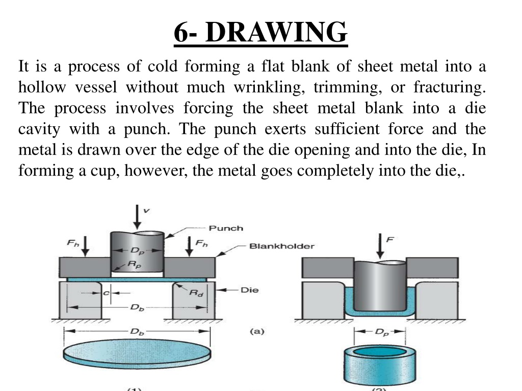
6- DRAWING It is a process of cold forming a flat blank of sheet metal into a hollow vessel without much wrinkling, trimming, or fracturing. The process involves forcing the sheet metal blank into a die cavity with a punch. The punch exerts sufficient force and the metal is drawn over the edge of the die opening and into the die,In forming a cup, however, the metal goes completely into the die,.
Fig 6.6 Drawing of a cup-shaped part: (1) start of operation before punch contacts work, and (2) near end of stroke; and (b) corresponding work part:(1) starting blank, and(2) drawn part. Symbols: c= clearance, Db = blank diameter, Dp = punch diameter, Rd = die corner radius, Rp = punch corner radius, F =drawing force, Fh = holding force. This clearance in drawing is about 10% greater than the stock thickness: c = 1.1t where c=clearance t= thickness
OPERATION,A setup similar to that used for blanking is used for drawing with the difference that the punch and die are given necessary rounding at the corners to permit smooth flow of metal during drawing. The blank of appropriate dimensions is place within the guides on the die plate. The punch descends slowly on the blank and metal is drawn into the die and the blank is formed into the shape of cup as punch reaches the bottom of the die. When the cup reaches the counter bored portion of the die, the top edge of the cup formed around the punch expands a bit due to the spring back. On the return stroke of the punch, the cup is stripped off the punch by this counter bored portion.
The term shallow drawingis used when the height of cup formed is less than half its diameter. When drawing deeper cup (height greater that diameter) the chances of excessive wrinkle formation at the edges of blank increases. To prevent this, a blank holder is normally provided, see Fig6.5. As the drawing process proceeds the blank holder stops the blank from increasing in thickness beyond a limit and allows the metal to flow radially. The limiting thickness is controlled by the gap between the die and the blank holder, or by the spring pressure in the case of a spring loaded blank holder. Some lubricant is generally used over the face of the blank to reduce friction and hence drawing load.
6-1 Blank Size It is generally difficult to find the exact size of the blank needed for drawing a given cup, because of thinning and thickening of the metal sheet during the drawing operation. The following simple relations can be used for determine the blank diameter D: D= ?2+ 4? 0.5?when d 20r D= ?2+ 4? ? when d is between 15r and 20r D= ?2+ 4? 5? when d is between 10r and 15r Where d = outside diameter of cup h = height of cup r = corner radius on punch.
6-2 Drawing Force. For drawing cylindrical shells having circular cross section, the maximum drawing force P can be determined from the relation P = k . .d .t .TS Where d = outside diameter of cup t = thickness of material TS = tensile strength of material k = factor whose value is approx. equal to [D/d 0.7] D = blank diameter 6-3 Holding Force (Fh) The holding force (Fh) is an important factor in a drawing operation. As a rough approximation, the holding pressure can be set at a value = 0.015 of the yield strength of the sheet metal. This value is then multiplied by that portion of the starting area of the blank that is to be held by the blank holder. In equation form, Fh=0.015Y {D2b-(Dp+2.2t+2Rd)2} Where Fn = holding force in drawing, N (lb); Y = yield strength of the sheet metal, MPa(lb/in2); t = starting stock thickness, mm (in); Rd = die corner radius, mm (in); and the other terms have been previously defined. The holding force is usually about one-third the drawing force.
6-4. drawing without a Blank holder One of the primary functions of the blank holder is to prevent wrinkling of the flange while the cup is being drawn. The tendency for wrinkling is reduced as the thickness-to-diameter ratio of the blank increases. If the = ratio is large enough, drawing can be accomplished without a blank holder, as in Figure 6.7.
6-5 DEFECTS IN DRAWING Sheet-metal drawing is a more complex operation than cutting or bending, and more things can go wrong. A number of defects can occur in a drawn product, some of which we have already alluded to. Following is a list of common defects, with sketches in Figure 6.8: (a) Wrinkling in the flange. Wrinkling in a drawn part consists of a series of ridges that form radially in the undrawn flange of the work part due to compressive buckling.
(b) Wrinkling in the wall. If and when the wrinkled flange is drawn into the cup, these ridges appear in the vertical wall. (c) Tearing. Tearing is an open crack in the vertical wall, usually near the base of the drawn cup, due to high tensile stresses that cause thinning and failure of the metal at this location. This type of failure can also occur as the metal is pulled over a sharp die corner.
(d) Earing. This is the formation of irregularities (called ears) in the upper edge of a deep drawn cup, caused by anisotropy in the sheet metal. If the material is perfectly isotropic, ears do not form. (e) Surface scratches. Surface scratches can occur on the drawn part if the punch and die are not smooth or if lubrication is insufficient
7- WIRE DRAWING Wire drawing is primarily the same as bar drawing except that it involves smaller diameter material that can be coiled. It is generally performed as a continuous operation on draw bench like the one shown in Fig 3.3 Wire drawing on a continuous draw block. The rotating draw block provides a continuous pull on the incoming wire.
Large coil of hot rolled material of nearly 10 mm diameter is taken and subjected to preparation treatment before the actual drawing process. The preparation treatment for steel wire consists of: Cleaning. This may be done by acid pickling, rinsing, and drying. Or, it may be done by mechanical flexing. Neutralization. Any remaining acid on the raw material is neutralized by immersing it in a lime bath. The corrosion protected material is also given a thin layer of lubricant.
To begin the drawing process, one end of coil is reduced in cross section up to some length and fed through the drawing die, and gripped. A wire drawing die is generally made of tungsten carbide and has the configuration shown in Fig 3.4 for drawing very fine wire, diamond die is preferred. Small diameter wire is generally drawn on fundamental machines which consist of a series of dies, each held in a water cooled die block. Each die reduces the cross section by a small amount so as to avoid excessive strain in the wire. Intermediate annealing of material between different states of wire may also be done, if required.
7-1 Wire drawing terms : Where Do , Df , Lo and Lf are the original and final diameter and length. Ao and Af are Original and final cross sectional area. Draft =Do -Df % reduction in area = ? ? ?? ?? ?? ?? ?? ?? 100 = ? ??? ?? ?? ?? % elongation = For a single cold drawing pass, the percent area reduction that can be done depends upon many factors. These include the type of material, its size, initial metallurgical condition, the final size and mechanical properties desired, die design and lubrication efficiency. The percent of area reduction per pass can range from near zero to 50%.
7-2 Die pull The force required to pull the stock through the die (under frictionless conditions) can be computed as follows. F = Yavg. Af. ln ?? Where F = die pull, i.e. the force required to pull the stock through the die Yavg = average true stress of the material in the die gap Ao , Af = original and final areas of cross section of material. Alternatively, the following expression can be used F = C St (Ao - Af ) where C is a constant whose value is in the range 1.5 to 3.0 depending upon the % area reduction, (lower value for higher % reduction), and St is tensile strength of material before drawing. The pull force determines the machine capacity needed. ??
8- EMBOSSING Embossing is an operation in which sheet metal is drawn to shallow depths with male and female matching dies, Fig 6.9. The operation is carried out mostly for the purpose of stiffening flat panels. The operation is also sometimes used decoration items like number plates or name plates, jewelry, etc. for making Embossing operation with two dies. Letters, numbers and designs on sheet-metal parts can be produced by this operation.
9- COINING Coining is a severe metal squeezing operation in which the flow of metal occurs only at the top layers of the material and not throughout the values. The operation is carried out in closed dies mainly for the purpose of producing fine details such as needed in minting coins, and medal or jewelry making. The blank is kept in the die cavity and pressures as high as five to six times the strength of material are applied. Depending upon the details required to be coined on the part, more than one coining operations may be used. The difference between coining and embossing is that the same design is created on both sides of the work piece in embossing (one side depressed and the other raised ), whereas in coining operation, a different design is created on each side of work piece.
10- Lancing Lancing is a combined cutting and bending or cutting and forming operation performed in one step to partially separate the metal from the sheet. Several examples are shown in Fig 6.10.Among other applications, lancing is used to make louvers in sheet metal air vents for heating and air conditioning systems in buildings. cutting and bending two types of cutting and forming..
11- Twisting Twisting subjects the sheet metal to a torsion loading rather than a bending load, thus causing a twist in the sheet over its length. This type of operation has limited applications. It is used to make such products as fan and propeller blades. It can be performed in a conventional punch and die which has been designed to deform the part in the required twist shape.

 start of operation")


 Wrinkling in the wall. If and")
 Earing. This is the formation of")