Understanding DC Motors: Principles and Operations

The introduction to DC motors covers the types of DC machines, such as generators and motors, and explains how they convert energy. By exploring the force on a current-carrying conductor in a magnetic field, the principles behind DC motor operation are clarified. The magnitude and direction of forces in DC motors are discussed, along with Fleming's left-hand rule for determining the direction of rotation. Understanding these fundamental concepts is essential for selecting and utilizing electrical machines effectively.

Download Presentation

Please find below an Image/Link to download the presentation.
The content on the website is provided AS IS for your information and personal use only. It may not be sold, licensed, or shared on other websites without obtaining consent from the author. Download presentation by click this link. If you encounter any issues during the download, it is possible that the publisher has removed the file from their server.
E N D
Presentation Transcript
DC MOTOR
Course outcome C403.4: Identify and select various electrical machines based on their characteristics and applications
Introduction The Dc machines are of two types namely DC generators and DC motors. A DC generators converts mechanical energy into electrical energy whereas a DC motor converts the electrical energy into mechanical energy. In order to understand the operating principle of a DC motor, it is necessary to understand how does a current carrying conductor experience a force, when kept in a magnetic field.
Force on current carrying conductor: If a straight conductor is placed in the magnetic field produced by a permanent magnet, the current flowing through a conductor in anti clockwise direction. Due to the presence of two magnetic fields simultaneously, an interaction between them will take place as shown in fig.(1).
Fig.1(a): Interaction of the fields Fig.1(b):Resultant field
As shown in fig.(1), the flux lines produced by the magnet and the conductor are in opposite direction to each other at left side and hence cancel each other. Therefore the no of flux lines at left side will reduced. At the right side, the individual fields are in the same direction, hence will add or strengthen each other. Therefore the no. of flux lines at right side will increase.
Magnitude of Force: The magnitude of the force experienced by the current carrying conductor placed in the magnetic field is given by, F = BIl Newton Where B = Flux density produced by Magnet I = current flowing through conductor l = Length of the conductor
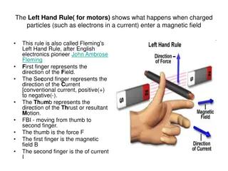
Direction of force: The direction of rotation of a motor depends on the direction of force exerted on the the armature winding and the direction of force experienced by a current carrying conductor is given by Fleming s left hand rule. Statement of Fleming s left hand rule: It states that if the first three fingers of the left hand are held mutually at right angles to each other and if index finger indicates the direction of the magnetic field, and if middle finger indicates the direction of current flowing through the conductor, then thumb indicates the direction of force exerted on the conductor. This is shown in fig (2).
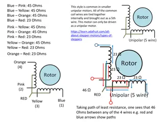
Windings in DC Machine In any dc machines, there are two windings: 1. Field winding 2. Armature winding Out of these, the field winding is stationary which does not move at all and armature winding is mounted on a shaft. So it can rotate freely. Connection of windings for operation as motor: To operate the dc machine as a motor, the field winding and armature winding is connected across a dc power supply.
DC Motor Principle of operation: When current carrying conductor is placed in a magnetic field, it experienced a force. In case of DC motor, the magnetic field us developed by the field current i.e. current flowing in field winding and armature winding plays the role of current carrying conductor So armature winding experienced a force and start rotating.
Construction of DC Motor Fig.(1): construction of DC motor
Important parts of DC motor: 1. Yoke 4. Armature 2. Field winding 5. Commutator, brushes & gear 3. poles 6. Brushes 1. Yoke: It acts as the outer support of a DC motor. It provides mechanical support for the poles.
2. Poles: pole of a dc motor is an electromagnet. The field winding is wound over the poles. Poles produces magnetic flux when the filed winding is excited. 3. Field winding: The coils wound around the pole are called field coils and they are connected in series with each other to form field winding. When current passing through the field winding, magnetic flux produced in the air gap between pole and armature.
4. Armature: Armature is a cylindrical drum mounted on shaft in which number of slots are provided. Armature conductors are placed in these slots. Theses armature conductors are interconnected to form the armature winding. 5. Commutator: A commutator is a cylindrical drum mounted on the shaft alonwith the armature core. It collects the current from the armature conductors and passed it to the external load via brushes.
6. Brushes: Commutator is rotating. So it is not possible to connect the load directly to it. Hence current is conducted from the armature to the external load by the carbon brushes which are held against the surface of commutator by springs.
Back EMF When the armature winding of a dc motor starts rotating in the magnetic flux produced by the field winding, it cuts the lines of magnetic flux. Hence according to the faraday s laws of electromagnetic induction, there will be an induced emf in the armature winding. As per the Lenz s law, this induced emf acts in opposite direction to the armature supply voltage. Hence this emf is called as the back emf and denoted by Eb.
Significance of back emf: The presence of back e.m.f. makes the d.c. motor a self -regulating machine i.e., it makes the motor to draw as much armature current as is just sufficient to develop the torque required by the load. 1. When the motor is running on no load, small torque is required to overcome the friction and windage losses. Therefore, the armature current Ia is small and the back e.m.f. is nearly equal to the applied voltage.
2. If the motor is suddenly loaded, the first effect is to cause the armature to slow down. Therefore, the speed at which the armature conductors move through the field is reduced and hence the back e.m.f. Eb falls. The decreased back e.m.f. allows a larger current to flow through the armature and larger current means increased driving torque. Thus, the driving torque increases as the motor slows down. The motor will stop slowing down when the armature current is just sufficient to produce the increased torque required by the load.
3. If the load on the motor is decreased, the driving torque is momentarily in excess of the requirement so that armature is accelerated. As the armature speed increases, the back e.m.f. Eb also increases and causes the armature current Ia to decrease. The motor will stop accelerating when the armature current is just sufficient to produce the reduced torque required by the load. It follows, therefore, that back e.m.f. in a d.c. motor regulates the flow of armature current i.e., it automatically changes the armature current to meet the Load requirement.


: Interaction of the fields")
, the flux lines produced by")


:Fleming’s left hand rule thumb")