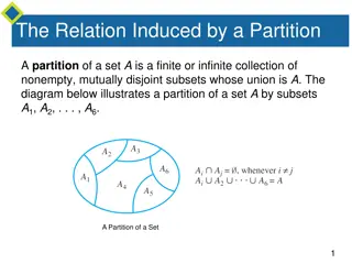
Geometrical and Kinetic Similarities: Understanding the Science of Equivalence

Explore the connection between entities in physics, such as inertia, pressure, and advance coefficients, and the Reynolds and Froude numbers. Learn about the principles of similarity in practice and how different characteristics are interrelated across various scientific fields.

Download Presentation

Please find below an Image/Link to download the presentation.
The content on the website is provided AS IS for your information and personal use only. It may not be sold, licensed, or shared on other websites without obtaining consent from the author. Download presentation by click this link. If you encounter any issues during the download, it is possible that the publisher has removed the file from their server.
E N D
Presentation Transcript
Kinematic Similarity Advance Coefficient
Inertia F. to gravity F. Froude Number Inertia F. to viscous F. Reynolds Number Pressure F. to Inertia F. Pressure Coefficient Euler Number
Laws of Similarity in Practice Can we do this ??
Reynolds Number Equality Equality of Advance Coefficients
Reynolds Number & Advance Coefficient & Thrust Coefficient are Equal
Froude Number & Advance Coefficient & Thrust Coefficient are Equal
Methodical Propeller Series Standard Series Gawn Series
Propeller Series Propeller Series Wageningen B Wageningen B Blades : 2-7 Pitch Ratio : 0.60~1.40 (Four bladed propeller has no constant pitch distribution) Area Ratio : 0.30~1.05 Skew Angles : 0o> Section Type : Original Remark : Most widely used propeller series. Suitable for most application. Frame 001 28 Sep 2007 Z Y X 0.15 0.1 0.05 Z 0 -0.05 -0.1 0 -0.15 0.05 X -0.1 -0.05 0 Y 0.1 0.05 0.1 0.15
Propeller Series Propeller Series Au Series Au Series Blades : 4-7 Pitch Ratio : 0.50~1.20 Area Ratio : 0.70~0.758 Skew Angles : 0o> Section Type : AU type Remark : Complemantary series of Wageningen B Series
Propeller Series Propeller Series Gawn Series Gawn Series Blades : 3 Pitch Ratio : 0.40~2.00 Area Ratio : 0.20~1.100 Skew Angles : 0o> Section Type : Circular Remark : Frame 001 28 Sep 2007 Z Y X 0.15 0.1 0.05 Z 0 -0.05 -0.1 0 -0.15 0.05 -0.1 X -0.05 0 Y 0.1 0.05 0.1 0.15
Propeller Series Propeller Series Ma Series (Lindgren Series) Ma Series (Lindgren Series) Blades : 3, 5 Pitch Ratio : 1.00~1.454 Area Ratio : 0.75~1.20 Skew Angles : 0o> Section Type : Circular
Propeller Series Propeller Series KCA Series KCA Series Blades : 3,4,5 Pitch Ratio : 0.60~2.00 Area Ratio : 0.20~1.10 Skew Angles : 0o> Section Type : Ogival Remark : Most widely use propeller series. Suitable for most application.
Propeller Series Propeller Series Skew KCA Series Skew KCA Series Blades : 3,4,5 Pitch Ratio : 0.60~2.00 Area Ratio : 0.50~1.10 Skew Angles : 25o, 30o, 35o Section Type : Ogival Remark : Modified from standard KCA series for smooth application. Suitable for most application.
Propeller Series Propeller Series NR Series NR Series Blades : 3, 4, 5 Pitch Ratio : 1.00~2.00 Area Ratio : 0.50~1.00 Skew Angles : 25o, 30o Section Type : Crescent Remark : Suitable for higher speed range in trans-cavitating application. Frame 001 28 Sep 2007 Z Y X 0.15 0.1 0.05 Z 0 -0.05 -0.15 -0.1 -0.1 0 -0.05 0 0.05 X Y 0.05 0.1 0.1 0.15
Propeller Series Propeller Series NACA NACA- -Series Series Blades : 4,5,6,7 Pitch Ratio : 0.80~1.60 Area Ratio : 0.50~1.40 Skew Angles : According to design Section Type : Airfoil Remark : Theoretical design propeller series.
Propeller Series Propeller Series New Foil Series New Foil Series Blades : 3,4,5 Pitch Ration : 0.80~1.60 Area Ration : 0.50~1.40 Skew Angles : According to design Section Type : New Foil Remark : Theoretical design propeller series.
Propeller Series Propeller Series Ka Ka Series Series Blades : 3, 4, 5 Pitch Ratio : 0.60~1.60 Area Ratio : 0.55~0.75 Skew Angles : 00,Skew available Section Type : Airfoil Remark : Suitable for accelerating nozzle propellers and bow or stern thrusters.
Propeller Propeller Selection Selection
Contents Contents Case 1: Optimum rotation rate for a given diameter Case 2: Optimum diameter for a given rotation rate Case 3: Optimum propeller for given power and rate Case 4: Maximum bollard pull Case 5: Existing propeller Viscous Effects ITTC Analysis Procedure
Case 1: Optimum Case 1: Optimum Rotation Rotation Rate Rate for for a a Given Given Diameter Diameter A common problem for the propeller is the design of a propeller when the required propeller thrust is known and the propeller diameter is known. The advance velocity of a propeller can be estimated from the ship speed and the wake fraction. The unknowns are the required power and especially the rate of rotation. The latter is important for the choice of the engine or for the choice of the gear ratio.
Suppose that a four-bladed propeller is chosen. In that case the following data are known: The propeller thrust T =1393 kN. The propeller diameter D = 7 m. The advance velocity Va= 8.65 m/s. The density of water = 1025 kg/m3. The number of blades Z = 4. Estimate the required area ratio to be 0.55. The diagram to be used is that of the B 4.55 series. The thrust and diameter are known but the rotation rate is not.
This means that the parameters Ktand J cannot be calculated yet. However, the parameters KT/J2 can be calculated because it does not contain the rotation rate: 1,393,000 1025 8.65 K J T = = = 0.3707 T V D 2 2 2 2 2 7 KT/J2 has to be found from variation of the pitch ratio.
By starting with a pitch ratio of 0.8 the following search is possible i ---|-------|-------|--------|--------|--------|------------|----------| 31 0.800 0.595 0.1310 0.1951 0.6356 16.9452 170.3291 41 0.900 0.648 0.1557 0.2480 0.6478 15.3963 156.2336 46 0.950 0.674 0.1684 0.2777 0.6503 14.7781 150.2568 51 1.000 0.699 0.1811 0.3095 0.6512 14.2379 144.8587 61 1.100 0.747 0.2071 0.3793 0.6493 13.3371 135.4951 71 1.200 0.793 0.2333 0.4568 0.6448 12.6087 127.6514 ---|-------|-------|--------|--------|--------|-----------|-----------| P/D J Kt 10Kq eta0 Bp delta WAGENINGEN B SERISI SECILEN PERVANE = 46. PERVANEDIR P/D=0.950 J= 0.674 Kt= 0.168 10Kq= 0.278 eta= 0.650 Bp= 14.7781 delta= 150.2568 T= 1393.00 kN Va= 8.650 m/s RHO = 1025.0 kg/m3 Z = 4. EAR = 0.550 D = 7.000 m RPS= 1.834 dev/san RPM= 110.01 TORK=1608.316 kNm Pd=18528.5 kW
After running the program, the conclusion is that the optimum efficiency can be reached with a pitch ratio of 0.95. The optimum efficiency is 0.650. The advance ratio J is 0.699 and from this the required rotation rate can be derived: 8.65 0.674 7 a V JD = = = 110 = 1.834 n RPS RPM The required power to propel ship can be derived from the torque coefficient KQ=0.0278. The torque is found to be = = 0.0277 1025 1.834 = 2 5 2 5 7 1608.316 Q K n D kNm Q The power to be delivered to the propeller is therefore 2 D P = Q n = 1608.316 1.834 18528.5 = 2 kW These data can be used to find a suitable engine
Case 2: Optimum diameter for a given rotation rate Case 2: Optimum diameter for a given rotation rate When the optimum rate of case 1 is chosen the question can be posed if the diameter of 7 meters was the optimum diameter. The optimum diameter can be calculated in a similar way as the optimum rotation rate, but now the value of KT/J4can be calculated because the diameter is absent in the parameter 2 2 1,393,000 1.834 1025 8.65 K J T n = = = 0.816 T 4 4 4 V
The optimum pitch ratio can again be found by iteration: ---|-------|-------|--------|--------|--------|------------|----------| i P/D J Kt 10Kq eta0 Bp delta ---|-------|-------|--------|--------|--------|------------|----------| 34 0.830 0.631 0.1294 0.2001 0.6497 14.7837 160.4543 35 0.840 0.635 0.1326 0.2060 0.6506 14.7737 159.4914 36 0.850 0.639 0.1358 0.2119 0.6513 14.7657 158.5511 41 0.900 0.657 0.1519 0.2434 0.6524 14.7529 154.1675 51 1.000 0.690 0.1851 0.3148 0.6459 14.8266 146.7318 71 1.200 0.747 0.2535 0.4886 0.6166 15.1745 135.6321 81 1.300 0.771 0.2880 0.5883 0.6007 15.3752 131.3755 91 1.400 0.793 0.3225 0.6936 0.5867 15.5564 127.7158 ---|-------|-------|--------|--------|--------|-----------|-----------| WAGENINGEN B SERISI SECILEN PERVANE = 35. PERVANEDIR P/D=0.840 J= 0.635 Kt= 0.133 10Kq= 0.206 eta= 0.651 Bp= 14.7737 delta= 159.4914 T= 1393.00 kN Va= 8.650 m/s RHO = 1025.0 kg/m3 Z = 4. EAR = 0.550 D = 7.431 m RPS= 1.833 dev/san RPM= 110.00 TORK=1607.891 kNm Pd=18521.6 kW


 Similarity")
 Similarity")