Understanding Passive/Active Resonant Transition in Power Amplifier
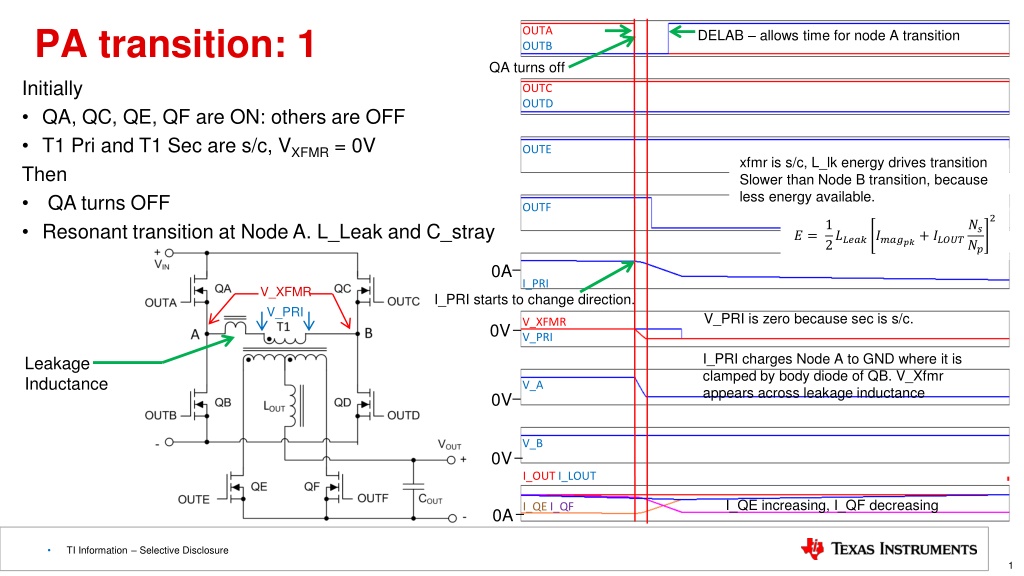
DELAB allows time for node A transition in PA with OUTA and OUTB. The transition is slower than AP transition, making ZVS harder to achieve across load range due to less energy. Transition time is shorter at higher currents, and the controller can adjust delays adaptively. Remember, the conditions for positive and negative transitions are the same.
Download Presentation

Please find below an Image/Link to download the presentation.
The content on the website is provided AS IS for your information and personal use only. It may not be sold, licensed, or shared on other websites without obtaining consent from the author. Download presentation by click this link. If you encounter any issues during the download, it is possible that the publisher has removed the file from their server.
E N D
Presentation Transcript
PA transition: 1 OUTA OUTB DELAB allows time for node A transition QA turns off Initially QA, QC, QE, QF are ON: others are OFF T1 Pri and T1 Sec are s/c, VXFMR = 0V Then QA turns OFF Resonant transition at Node A. L_Leak and C_stray OUTC OUTD OUTE xfmr is s/c, L_lk energy drives transition Slower than Node B transition, because less energy available. OUTF 2 1 2???????????+ ????? ?? ?? ? = 0A I_PRI V_XFMR I_PRI starts to change direction. V_PRI V_PRI is zero because sec is s/c. V_XFMR V_PRI 0V I_PRI charges Node A to GND where it is clamped by body diode of QB. V_Xfmr appears across leakage inductance Leakage Inductance V_A 0V V_B 0V I_OUT I_LOUT I_QE increasing, I_QF decreasing I_QE I_QF 0A TI Information Selective Disclosure 1
PA transition: 2 OUTA OUTB QC, QE, QF are ON: others are OFF QA is OFF OUTC OUTD OUTE Resonant transition is finished BUT Pri current is still reversing and Iout is moving out of QF and into QE QF turned off after DELAF, QF current moves into body diode, sec remains s/c OUTF di/dt is V_XFMR / L_leak. Current reverses 0A I_PRI V_XFMR V_PRI is zero because sec is s/c. V_Xfmr appears across leakage inductance V_PRI V_XFMR V_PRI 0V Leakage Inductance V_A clamped by body diode of QB. V_A 0V V_B 0V I_OUT I_LOUT I_QE I_QF 0A TI Information Selective Disclosure 2
PA transition: 3 OUTA OUTB QB turns on at 0V (ZVS) QC, QE, QF are ON: others are OFF T1 is short circuited by QE & QF so VXFMR = 0V Output current supplied by Lout I_PRI is changing direction QB current is initially in the body diode, must turn it on before I_Pri goes through zero and reverses. I_Lout current moving out of QE and into QF OUTC OUTD OUTE OUTF di/dt is V_XFMR / L_leak. Current reverses 0A I_PRI V_XFMR V_PRI is zero because sec is s/c. V_Xfmr appears across leakage inductance V_PRI V_XFMR V_PRI 0V Leakage Inductance V_A 0V V_B 0V I_OUT I_LOUT I_QE I_QF 0A TI Information Selective Disclosure 3
PA transition: 4 OUTA OUTB QB turns on at 0V (ZVS) QA, QC, QE, QF are ON: others are OFF T1 Primary is short circuited, VXFMR = 0V T1 Sec is short circuited by QE & QF Output current supplied by Lout QA turns QB: turns ON OUTC OUTD OUTE OUTF Primary current reversal complete 0A I_PRI V_XFMR V_PRI V_XFMR V_PRI V_PRI increases to Vin as sec s/c released 0V Leakage Inductance V_A 0V V_B 0V I_QF reaches zero, body diode turns off. Sec s/c is released. V_PRI increases to Vin I_OUT I_LOUT I_QE I_QF 0A TI Information Selective Disclosure 4
PA transition: Summary DELAB allows time for node A transition OUTA OUTB PA = Passive/Active Resonant transition Slower than AP transition, More difficult to achieve ZVS across load range because less energy available. OUTC OUTD Transition takes less time at higher currents. Controller can reduce the delay DELAB time at higher currents Adaptive Delays OUTE 2 1 2???????????+ ????? ?? ?? ? = OUTF Remember, conditions for the positive going PA leg transition are the same as those for the negative going PA transition. 0A I_PRI V_XFMR V_PRI Neg and Pos going PA transitions are identical (just change polarity and swap QE and QF) V_XFMR V_PRI 0V V_A 0V V_B 0V I_OUT I_LOUT I_QE I_QF 0A TI Information Selective Disclosure 5
AP transition: 1 OUTA OUTB QD turns off Initially QA, QD, QF are ON: others are OFF Then QD turns OFF Linear transition at Node B OUTC OUTD DELCD allows time for node B transition OUTE 2 2 2 OUTF ?? ?? 1 2???????????+ ????? ?? ?? +1 ?? ?? +1 2 ? = 2???? ????? 2?????????? xfmr is not s/c. Faster than Node A transition, because more energy available. 0A I_PRI V_XFMR V_PRI V_XFMR V_PRI 0V Xfmr windings are not s/c. V_XFMR V_PRI. V_A 0V I_PRI charges Node B to Vin where it is clamped by body diode of QC. V_B 0V I_OUT I_LOUT >0A TI Information Selective Disclosure 6
AP transition: 2 OUTA OUTB Initially QA, QD, QF are ON: others are OFF Then QC and QE turn on at same time I pri continues to flow in Pri, QA, QC loop I_OUT supplied by Lout. Current flows asymmetrically in T1 Sec previous slides OUTC OUTD QC and QE turn on at same time: Xfmr is s/c OUTE OUTF I_PRI does not change direction. 0A I_PRI V_XFMR V_PRI V_XFMR V_PRI 0V Xfmr windings are s/c when QE turns on. V_A 0V Node B is clamped by body diode of QC. V_B 0V I_OUT I_LOUT I_LOUT continues to flow in same SR (QE or QF). >0A TI Information Selective Disclosure 7
AP transition: Summary OUTA OUTB DELCD allows time for node B transition AP = Active/Passive Resonant transition Faster than PA transition, Easier to achieve ZVS across load range because moreenergy available. OUTC OUTD Transition takes less time at higher currents. Controller can reduce the delay DELCD time at higher currents Adaptive Delays OUTE 2 2 2 OUTF ?? ?? 1 2???????????+ ????? ?? ?? +1 ?? ?? +1 2 ? = 2???? ????? 2?????????? Remember, conditions for the positive going AP leg transition are the same as those for the negative going AP transition. 0A I_PRI V_XFMR V_PRI Neg and Pos going AP transitions are identical (just change polarity and swap QE and QF) V_XFMR V_PRI 0V V_A 0V V_B 0V I_OUT I_LOUT >0A TI Information Selective Disclosure 8
SR Transitions: QE turns off after DELBE PA = Passive/Active Current has to transfer out of one SR into the other. Takes time current ramps up in one and down in the other. SRs always switch with zero volts. SR turns off before current goes negative (VERY important) DELBE associated with positive transition at PA leg DELAF associated with negative transition at PA leg DELBE = DELAF OUTE OUTF 0V QB turns off QE body diode conduction V_PRI V_XFMR 0V SR current will go negative and be carried in Channel if SR not turned off. Destructive voltage spike if SR turned off with neg current Note unequal current sharing , I_QE and I_QF See: Timing Diagram: 3 I_LOUT I_OUT I_QE I_QF 0A Yel: I_LOUT Red: Vds SR Blu: OUTC Grn: OUTF QE current will go negative* if channel not off by here V_QE V_QF 0V * Negative current means from drain to source. TI Information Selective Disclosure 9
SR Transitions: QE turns off after DELBE PA = Passive/Active DELBE (and DELAF) allow time for node transition. Ideally SR turned OFF after Pri ZVS and before SR current goes negative (from drain to source). Turning OFF too soon, increased body diode conduction Turn OFF too late, reversed current in MOSFET, avalanching and MOSFET destruction likely. OUTE OUTF 0V QB turns off QE body diode conduction V_PRI V_XFMR 0V Transition takes more time at higher currents. Controller can increase the delay time at higher currents to reduce body diode conduction time Adaptive Delays Note unequal current sharing , I_QE and I_QF See: Timing Diagram: 3 I_LOUT I_OUT I_QE I_QF Remember, conditions for the positive going PA leg transition are the same as those for the negative going PA transition 0A QE current will go negative* if channel not off by here V_QE V_QF 0V TI Information Selective Disclosure 10
SR Transitions: OUTF and OUTD turn on at same time AP = Active/Passive SRs see ZVS at AP transition SR turn on is co-incident with primary side switch OUTD/OUTF and OUTC/OUTE Primary of transformer is S/C by OUTD/OUTB or OUTA/OUTC Secondary of transformer is S/C by OUTE and OUTF Transition takes more time at higher currents. Controller can increase the delay time at higher currents Adaptive Delays OUTE OUTF 0V V_PRI V_XFMR 0V Remember, conditions for the positive going PA leg transition I_LOUT I_OUT I_QE I_QF 0A VDS is 0 at SR turn-on V_QE V_QF 0V TI Information Selective Disclosure 11
Duty cycle loss: Energy is transferred from primary to secondary during the transformer ON time (green). The energy needed to drive the load current during the transformer OFF time is supplied by the output inductor. The time needed to achieve the ZVS transition in the PA leg (Node A or Left hand leg) adds to the OFF time. And sets a maximum duty cycle. 0A There is a trade off between this time and the leakage inductance needed to achieve ZVS. Not a critical problem at 100kHz but will be come worse as frequency increase. 0V 0V 0V >0A TI Information Selective Disclosure 12
