Alternative Test Procedure for Ensuring Driver Awareness of Endangered Bicyclists


BSIS Alternative
Test Procedure
Informal Document GRSG-122-20
(122nd GRSG, 12-15 October 2021, Agenda item 4)


Motivation
Regulation 151-00 guarantees that drivers of heavy vehicles are
notified about endangered bicyclists in due time.
Main critisicm:
Information signal is given too early
Solution: New, alternative test procedure
Alternative test procedure allows verification of AEBS for BSIS
(original test procedure does not)
Introduction &
Recapitulation
Possible information signal timings
1
before potential swerving (as implemented in current R151)
2
for comfortable stopping (as proposed in initial document)
3
possible auto-brake activation
1
2
3
Sufficient
to initiate braking
Sufficient
for Auto-Brake!
Figure qualitative
R151 requirements …
The BSIS shall inform the driver about nearby
bicycles that might be endangered during a
potential turn, by means of an optical signal, so
that the vehicle can be stopped before crossing
the bicycle trajectory
.
It shall also inform the driver about approaching
bicycles while the vehicle is stationary
before the
bicycle reaches the vehicle front, taking into
account a reaction time of 1.4 seconds.
This shall
be tested according to paragraph 6.6.
The BSIS shall warn the driver, by means of an
optical signal, acoustical signal, haptic signal or
any combination of these signals, when the risk of
a collision increases.
Needs additional
definitions or at
least interpretation
Clear performance
requirement
Needs interpretation
Proposal for alternative test method
1. When using driving and dummy robots, all vehicle movements are
pre-programmed
2. Every vehicle location is known at all times
3. It is possible to verify the signal activation without impact to the
dummy
4. It is possible to verify the signal activation in more realistic
scenarios (including swerving to the outside)
5. It is safe to return to the „old“ pass-fail-criteria!
6. NO changes to actual specification section in R151 required
Technical Feasibility
Central question:
„Will it be possible to drive the vehicle naturally and add a bicycle
dummy to verify the functionality of the system?“
Driving Robots
Dummy Robots
Recording of Trajectories
Robot Implementation Overview
Vehicle
Sensor: ADMA G DGPS IMU
Actor: ABD SR 60
(60 Nm steering robot)
Actor: ABD CBAR
(combined brake +
accelerator robot)
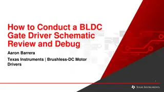
Steering Controller (Details)
Investigated Variants
Replay recorded trajectory from other vehicles
not promising
Replay recorded trajectory from same vehicle
accuracy sufficient, speed control critical
Synchronise trajectory with bicycle dummy
accuracy sufficient, solves speed control issue
Accuracy results for trajectories from other vehicles:
15 km/h, Klothoide
±0.35 m error
Position accuracy if trajectory recorded with the exact
same vehicle:
approx. 5 cm!
Actual vs.
Desired Speed:
Speed accuracy is not
as good as expected
due to shifting
(slow gearbox).
Possible to improve
with sync‘ed dummy.
Procedure
Record
t
rajectory
(path+speed) of realistic turn
Replay
t
rajectory
without dummy and record again
with dummy controller
Add dummy trajectory with
dummy controller software
Define impact position
Perform sync‘ed test without dummy to
check repeatability (overrun platform!)
Test synchronized (abort before impact)
1. Record turn with
out dummy
2. Add dummy
3. Perform test with
vehicle and dummy
Videos
Videos removes for presentation size
Results: Repeatability of Impact Situation
1
2
3
4
5
6
7
8
9
„Teached“ impact
Measurement Data
≤10 cm
≤10 cm
Outlier within ±20 cm
Speed Profiles – Vehicle (recorded) & Dummy (sync‘ed)
Desired Speed
± 1 km/h
Equipment (for reference)
Daimler Actros (last generation), driven in automatic transmission
mode
ABD „SR60“ + „CBAR“ Driving robots
Genesys „ADMA-G“ Version 3 DGPS-IMU
4active Systems „FreeBoard Small“ self-driving dummy platform
Syncronisation via ADMA protocol and WiFi network
Conclusion
Robot testing allows a robust assessment of Blind Spot Assist
Systems
Robot testing would allow assessment of Blind Spot AEB systems as
well (R151 test procedure does not!), sync tuning needed
Repeatability and accuracy is sufficient (when synchronized with
dummy)
How should the vehicles be driven in turns?
Trajectories for VUT
Trajectory Definition for Alternative Test Procedure
Several runs for different kinds of vehicle available
•
All manufacturers were invited to supply data
•
Truck
•
Truck & Trailer
•
Tractor & Semitrailer
•
Different lane width of target lane
Required is a generic specification for the turning path
Vehicles should be driven according to specification (without
dummy), this will be recorded as basis for the robot control
This is
independent
from dummy lateral distance!
Overview and combination of available data
4 = 1 + 3, so not necessary
Busses
4
5
Envelope 1
Several test runs of a single truck
Target lane width: 5 & 6 m
„Envelope“ for all test runs
„Envelope“ given per dedicated positions
Vehicle should be driven in the envelope
Envelope given per dedicated points as shown
Speed control open to the driver
Outlier
Several test runs of a truck & trailer
Target lane width: 7 & 9 m
„Envelope“
Envelope 2
Envelope 3
Several test runs for single truck
& tractor-semitrailer
Target lane widths: 7, 11 (truck)
& 11 (tractor-semitrailer)
„Envelope“
Envelope new 4 (Bus 1)
Envelope new 5 (Bus 2)
Conclusion
Bringing it all
together
Changes to the core test
“6.5.7.
Verification of Blind Spot Information signal
Verification of the Blind Spot Information signal can be made by following
two methods, at the manufacturer's choosing:
(a)
Verify if the Blind Spot Information signal has been activated before the vehicle
crosses line C in Figure 1 of Appendix 1 to this Regulation, and if the Blind Spot
Information signal has not been activated before the vehicle crosses line D in Figure 1.
(b)
The activation of the blind spot information signal may be checked using the
test procedure as specified in Annex 4 to this regulation.”
Annex 4: Prerequisites
1.
Test procedure
1.1.
Verify that the vehicle and the test track are in the condition as required per section 6 and its subparagraphs.
1.2.
Equip the vehicle with the following equipment:
1.2.1.
A position measurement system, able to measure the vehicle position with an accuracy of [5] cm, such as a
differential GPS and inertial measurement unit fusion system, sampling at no less than 100 Hz.
1.2.2.
A driving system that is able to modulate the direction, deceleration and acceleration of the vehicle under test
in order to follow recorded trajectories with an accuracy of [50] cm when comparing recorded and replayed trajectory
over time.
If the driving system does not allow a sufficient manual control, it may be absent during the recording of the
trajectory as defined in paragraph 1.3 below.
1.2.3.
A system to detect the information and warning signals after their activation with a time delay of not more than
[25] ms.
Annex 4: Procedure to record the trajectories
1.3
Drive manually and record vehicle position over time for all relevant envelopes described in
Appendix 1 for the vehicle under test. Modulate the speed as necessary during the turn while staying in the
performance requirements as specified in section 5.3.1. (e.g. up to 30 km/h vehicle speed). The initial speed
as specified in Appendix 1 should be maintained until passing a line corresponding to x=-30 in the coordinate
system as specified in Appendix 1.
The vehicle shall be driven in such a way that the vehicle front is inside the envelopes at all times.
This shall be verified with the measured data.
A marking of the positions using markers is permitted but not necessary.
If deemed justified by the technical service, any other trajectories that would be driven with the
given vehicle to negotiate 90° turns may be tested as well.
Annex 4: Procedure to perform the actual tests
1.4
Drive the tests according to the table in appendix 1, using the driving system and the trajectories as
recorded while performing paragraph 1.4 of this annex, ensuring the bicycle dummy robot is synchronized to
impact the vehicle under test at the respective impact position (the front right corner or a position 6 m behind
the front right corner of the vehicle) and is travelling on the respective y coordinate.
It may be necessary and shall be allowed to synchronize the dummy robot against a replay of the
VUT trajectories (with full driving system control over speed and steering) rather than against the originally
recorded trajectory while driving manually.
The dummy speed shall be at the respective speed with a tolerance of +- 2 km/h at all times. The
dummy shall be moving at speed sufficiently ahead for the blind spot information system to pick it up as a
moving target.
If the correct collision position for each VUT trajectory has been verified with a test run without a
dummy on the carrier platform and repeatability of the test setup has been verified as well, the test may be
aborted after detection of the information signal.
Annex 4: Calculation of LPI
1.5.
Calculate the stopping distance with respect to passing the bicycle trajectory for each individual
trajectory and each available sampling point, taking into account a possible vehicle deceleration of 5 m/s² and a
reaction time of 1.4 seconds.
The calculation may be performed in the following manner:
Calculate the required braking distance
d
brake
for each data point on the trajectory, using the following
equation:
using the actual vehicle speed
v
in m/s.
The distance of the VUT front right corner on its path to the bicycle line of movement shall be
d
Bicycletrajecrory.
The position of the last point of information then is given by the first time where the following condition
applies:
|
d
Bicycletrajecrory.
-
d
brake,total
| < [0.35] m
Annex 4 – Final paragraphs
1.6
The test procedure is considered to be passed, and consequently the vehicle is
deemed to have fulfilled paragraphs 6.5.6, 6.5.7 and 6.5.10, if the information signal is
given at a distance (on the path coordinate of the individual trajectories) greater than the
stopping distance (on the path coordinate of the individual trajectories) as calculated in
paragraph 1.4 above for all required test runs conducted according to paragraph 1.5 above.
1.7
All measurement data (in the form of plots) and all calculations done in paragraph
1.4 shall be included in a test report with regard to this annex. The test report shall be
annexed to the certificate.
Appendix 1 to Annex 4
Suggestion to just
put the envelope
pictures
Appendix 1 to Annex 4 – What to do
GRSG-122-20 discusses Regulation 151-00, highlighting the need for timely information to drivers of heavy vehicles regarding nearby bicyclists. The main criticism addressed is the early signaling issue, proposing a new alternative test procedure for verifying Advanced Emergency Braking Systems. The document outlines possible signal timings and requirements for the Blind Spot Information System, along with a proposal for a technical test method to ensure system functionality. Overall, the focus is on improving safety measures for protecting bicyclists on the road.

Download Presentation

Please find below an Image/Link to download the presentation.
The content on the website is provided AS IS for your information and personal use only. It may not be sold, licensed, or shared on other websites without obtaining consent from the author. Download presentation by click this link. If you encounter any issues during the download, it is possible that the publisher has removed the file from their server.
E N D
Presentation Transcript
Informal Document GRSG-122-20 (122nd GRSG, 12-15 October 2021, Agenda item 4) BSIS Alternative Test Procedure 1
Motivation Regulation 151-00 guarantees that drivers of heavy vehicles are notified about endangered bicyclists in due time. Main critisicm: Information signal is given too early Solution: New, alternative test procedure Alternative test procedure allows verification of AEBS for BSIS (original test procedure does not) 2 Name
Introduction & Recapitulation
Possible information signal timings 1 before potential swerving (as implemented in current R151) 2 for comfortable stopping (as proposed in initial document) 3 possible auto-brake activation Figure qualitative 3 2 1 Sufficient for Auto-Brake! Sufficient to initiate braking 4 Name
R151 requirements The BSIS shall inform the driver about nearby bicycles that might be endangered during a potential turn, by means of an optical signal, so that the vehicle can be stopped before crossing the bicycle trajectory. It shall also inform the driver about approaching bicycles while the vehicle is stationary before the bicycle reaches the vehicle front, taking into account a reaction time of 1.4 seconds. This shall be tested according to paragraph 6.6. The BSIS shall warn the driver, by means of an optical signal, acoustical signal, haptic signal or any combination of these signals, when the risk of a collision increases. Needs additional definitions or at least interpretation Clear performance requirement Needs interpretation 5 Name
Proposal for alternative test method 1. When using driving and dummy robots, all vehicle movements are pre-programmed 2. Every vehicle location is known at all times 3. It is possible to verify the signal activation without impact to the dummy 4. It is possible to verify the signal activation in more realistic scenarios (including swerving to the outside) 5. It is safe to return to the old pass-fail-criteria! 6. NO changes to actual specification section in R151 required 6 Name
Central question: Will it be possible to drive the vehicle naturally and add a bicycle dummy to verify the functionality of the system? Driving Robots Dummy Robots Recording of Trajectories 8 Name
Robot Implementation Overview Actor: ABD SR 60 (60 Nm steering robot) Sensor: ADMA G DGPS IMU Vehicle Actor: ABD CBAR (combined brake + accelerator robot) 9 Name
Steering Controller (Details) 10 Name
Investigated Variants Replay recorded trajectory from other vehicles not promising Replay recorded trajectory from same vehicle accuracy sufficient, speed control critical Synchronise trajectory with bicycle dummy accuracy sufficient, solves speed control issue 11 Name
Accuracy results for trajectories from other vehicles: 15 km/h, Klothoide 0.35 m error 12 Name
Position accuracy if trajectory recorded with the exact same vehicle: approx. 5 cm! 13 Name
Actual vs. Desired Speed: Speed accuracy is not as good as expected due to shifting (slow gearbox). Possible to improve with sync ed dummy. 14 Name
Procedure Record trajectory (path+speed) of realistic turn 1. Record turn without dummy Replay trajectory without dummy and record again with dummy controller Add dummy trajectory with dummy controller software 2. Add dummy Define impact position Perform sync ed test without dummy to check repeatability (overrun platform!) 3. Perform test with vehicle and dummy Test synchronized (abort before impact) 15 Name
Videos Videos removes for presentation size 16 Name
Results: Repeatability of Impact Situation 1 2 3 Teached impact 4 5 6 7 8 9 17 Name
Measurement Data Outlier within 20 cm 10 cm 10 cm 18 Name
Speed Profiles Vehicle (recorded) & Dummy (synced) Desired Speed 1 km/h 19 Name
Conclusion Robot testing allows a robust assessment of Blind Spot Assist Systems Robot testing would allow assessment of Blind Spot AEB systems as well (R151 test procedure does not!), sync tuning needed Repeatability and accuracy is sufficient (when synchronized with dummy) How should the vehicles be driven in turns? 21 Name
Trajectory Definition for Alternative Test Procedure Several runs for different kinds of vehicle available All manufacturers were invited to supply data Truck Truck & Trailer Tractor & Semitrailer Different lane width of target lane Required is a generic specification for the turning path Vehicles should be driven according to specification (without dummy), this will be recorded as basis for the robot control This is independent from dummy lateral distance! 23 Name
Overview and combination of available data 1 3 2 4 = 1 + 3, so not necessary 4 3 24 Name
Busses 4 5 25 Name
Envelope 1 Several test runs of a single truck Target lane width: 5 & 6 m Envelope for all test runs Envelope given per dedicated positions Vehicle should be driven in the envelope Envelope given per dedicated points as shown Speed control open to the driver 26 Name
Envelope 2 Outlier Several test runs of a truck & trailer Target lane width: 7 & 9 m Envelope 27 Name
Envelope 3 Several test runs for single truck & tractor-semitrailer Target lane widths: 7, 11 (truck) & 11 (tractor-semitrailer) Envelope 28 Name
Envelope new 4 (Bus 1) 29 Name
Envelope new 5 (Bus 2) 30 Name
Conclusion Kind of vehicle Single trucks, single tractors Single trucks equipped to tow trailers Tractors equipped to tow semitrailers M3 Class I M3 Other Relevant envelope 1, 3 1, 2, 3 3 4,5 5 31 Name
Bringing it all together
Changes to the core test 6.5.7. Verification of Blind Spot Information signal Verification of the Blind Spot Information signal can be made by following two methods, at the manufacturer's choosing: (a) crosses line C in Figure 1 of Appendix 1 to this Regulation, and if the Blind Spot Information signal has not been activated before the vehicle crosses line D in Figure 1. Verify if the Blind Spot Information signal has been activated before the vehicle (b) test procedure as specified inAnnex 4 to this regulation. The activation of the blind spot information signal may be checked using the 33 Name
Annex 4: Prerequisites 1. Test procedure 1.1. Verify that the vehicle and the test track are in the condition as required per section 6 and its subparagraphs. 1.2. Equip the vehicle with the following equipment: 1.2.1. differential GPS and inertial measurement unit fusion system, sampling at no less than 100 Hz. A position measurement system, able to measure the vehicle position with an accuracy of [5] cm, such as a 1.2.2. in order to follow recorded trajectories with an accuracy of [50] cm when comparing recorded and replayed trajectory over time. A driving system that is able to modulate the direction, deceleration and acceleration of the vehicle under test If the driving system does not allow a sufficient manual control, it may be absent during the recording of the trajectory as defined in paragraph 1.3 below. 1.2.3. [25] ms. A system to detect the information and warning signals after their activation with a time delay of not more than 34 Name
Annex 4: Procedure to record the trajectories 1.3 Appendix 1 for the vehicle under test. Modulate the speed as necessary during the turn while staying in the performance requirements as specified in section 5.3.1. (e.g. up to 30 km/h vehicle speed). The initial speed as specified in Appendix 1 should be maintained until passing a line corresponding to x=-30 in the coordinate system as specified inAppendix 1. Drive manually and record vehicle position over time for all relevant envelopes described in The vehicle shall be driven in such a way that the vehicle front is inside the envelopes at all times. This shall be verified with the measured data. Amarking of the positions using markers is permitted but not necessary. If deemed justified by the technical service, any other trajectories that would be driven with the given vehicle to negotiate 90 turns may be tested as well. 35 Name
Annex 4: Procedure to perform the actual tests 1.4 recorded while performing paragraph 1.4 of this annex, ensuring the bicycle dummy robot is synchronized to impact the vehicle under test at the respective impact position (the front right corner or a position 6 m behind the front right corner of the vehicle) and is travelling on the respective y coordinate. Drive the tests according to the table in appendix 1, using the driving system and the trajectories as It may be necessary and shall be allowed to synchronize the dummy robot against a replay of the VUT trajectories (with full driving system control over speed and steering) rather than against the originally recorded trajectory while driving manually. The dummy speed shall be at the respective speed with a tolerance of +- 2 km/h at all times. The dummy shall be moving at speed sufficiently ahead for the blind spot information system to pick it up as a moving target. If the correct collision position for each VUT trajectory has been verified with a test run without a dummy on the carrier platform and repeatability of the test setup has been verified as well, the test may be aborted after detection of the information signal. 36 Name
Annex 4: Calculation of LPI 1.5. trajectory and each available sampling point, taking into account a possible vehicle deceleration of 5 m/s and a reaction time of 1.4 seconds. Calculate the stopping distance with respect to passing the bicycle trajectory for each individual The calculation may be performed in the following manner: Calculate the required braking distance dbrakefor each data point on the trajectory, using the following equation: ??????,?????= ?? ? ??/? + ?.?? ?, using the actual vehicle speed v in m/s. The distance of the VUT front right corner on its path to the bicycle line of movement shall be dBicycletrajecrory. The position of the last point of information then is given by the first time where the following condition applies: |dBicycletrajecrory.- dbrake,total| < [0.35] m 37 Name
Annex 4 Final paragraphs 1.6 deemed to have fulfilled paragraphs 6.5.6, 6.5.7 and 6.5.10, if the information signal is given at a distance (on the path coordinate of the individual trajectories) greater than the stopping distance (on the path coordinate of the individual trajectories) as calculated in paragraph 1.4 above for all required test runs conducted according to paragraph 1.5 above. The test procedure is considered to be passed, and consequently the vehicle is 1.7 1.4 shall be included in a test report with regard to this annex. The test report shall be annexed to the certificate. All measurement data (in the form of plots) and all calculations done in paragraph 38 Name
Appendix 1 to Annex 4 Suggestion to just put the envelope pictures 39 Name
Appendix 1 to Annex 4 What to do Scenarios (other parameters possible as long as those are within the limits as defined in the core text) Envelope Lateral bicycle coordinate with respect to dummy center, in the coordinate systems as shown above -2.8 m, -5.8 m Bicycle speed Initial vehicle speed Impact position Single trucks, single tractors Trucks equipped to tow trailers Tractors (equipped to tow semitrailers) M3 of Class I 1,3 10 km/h, 20 km/h 10 km/h, 20 km/h 10 km/h, 20 km/h 10 km/h, 20 km/h 0m, 6m 1, 2, 3 -2.8 m, -5.8 m 0m, 6m 1, 3 -2.8 m, -5.8 m 10 km/h, 20 km/h 10 km/h, 20 km/h 0m, 6m 4 -2.8 m, -5.8 m 10 km/h, 20 km/h 10 km/h, 20 km/h 10 km/h, 20 km/h 10 km/h, 20 km/h 0m, 6m All other M3 5 -2.8 m, -5.8 m 0m, 6m Place the relevant stop signs somewhere on the trajectory. 40 Name


")


 & Dummy (sync‘ed)")


")
")