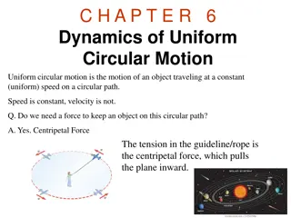
Understanding Circular Failure in Rock Slopes: Causes and Design Considerations

Circular failure in rock slopes, such as those containing discontinuities or weak materials like highly weathered or fractured rock, occurs along circular surfaces. This type of failure is common when geological features are not clearly defined. Factors influencing circular failure, conditions under which it occurs, and the use of circular failure charts for designing safe slopes are discussed in detail.

Download Presentation

Please find below an Image/Link to download the presentation.
The content on the website is provided AS IS for your information and personal use only. It may not be sold, licensed, or shared on other websites without obtaining consent from the author. Download presentation by click this link. If you encounter any issues during the download, it is possible that the publisher has removed the file from their server.
E N D
Presentation Transcript
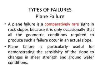
Circular Failure Plane and wedge failures are concerned with the stability of rock slopes containing well- defined sets of discontinuities. It is also necessary to design cuts in weak materials such as highly weathered or closely fractured rock and rock fills. In such materials, failure occurs along a surface that approaches a circular shape.
In previous types of failures, it has been assumed that the failure of rock slopes is controlled by geological features such as bedding planes and joints that divide the rock into a discontinuous mass. Under these conditions, one or more of the discontinuities normally defines the slide surface. However, in the case of a closely fractured or highly weathered rock, a strongly defined structural pattern no longer exists. The slide surface is free to find the line of least resistance through the slope known as critical surface. Observations of slope failures in these materials suggest that this slide surface generally takes the form of a circle.
Conditions The conditions under which circular failure will occur arise when the individual particles in a soil or rock mass are very small compared with the size of the slope. Hence, broken rock in a fill will tend to behave as a soil and fail in a circular mode when the slope dimensions are substantially greater than the dimensions of the rock fragments. Similarly, soil consisting of sand, silt and smaller particle sizes will exhibit circular slide surfaces, even in slopes only a few meters in height. Highly altered and weathered rocks, as well as rock with closely spaced, randomly oriented discontinuities such as some rapidly cooled basalts, will also tend to fail in this manner. It is appropriate to design slopes in these materials on the assumption that a circular failure process will develop.
Circular Failure Charts These charts can be used to determine rapidly the factor of safety of circular failures. These charts have been developed by running many thousands of circular analyses from which a number of dimensionless parameters were derived that relate the factor of safety to the material unit weight, friction angle and cohesion, and the slope height and face angle. It has been found that these charts give a reliable estimate for the factor of safety, provided that the conditions in the slope meet the assumptions used in developing the charts. In fact, the accuracy in calculating the factor of safety from the charts is usually greater than the accuracy in determining the shear strength of the rock mass.
Assumptions The conditions in the slope should meet the following assumptions: (a) The material forming the slope is homogeneous, with uniform shear strength properties along the slide surface. (b) The shear strength of the material is characterized by cohesion c and a friction angle , that are related by the equation =c + tan . (c) Failure occurs on a circular slide surface, which passes through the toe of the slope. (d) A vertical tension crack occurs in the upper surface or in the face of the slope.
(e)The locations of the tension crack and of the slide surface are such that the factor of safety of the slope is a minimum for the considered slope geometry and ground water conditions. (f) Ground water conditions vary from a dry slope to a fully saturated slope under heavy recharge; these conditions are defined in next figure. (g) Circular failure charts are optimized for a rock mass density of 18.9 kN/m3. Densities higher than this give high factors of safety, densities lower than this give low factors of safety. Detailed circular analysis may be required for slopes in which the material density is significantly different from 18.9 kN/m3.
Ground water flow models used with circular failure analysis charts
Use of Circular Failure Charts In order to use the charts to determine the factor of safety of a slope, the following steps should be followed. 1: Decide upon the ground water conditions which are believed to exist in the slope and choose the chart which is closest to these conditions. 2: Select rock strength parameters applicable to the material forming the slope. 3: Calculate the value of the dimensionless ratio c/( H tan ) and find this value on the outer circular scale of the chart. 4: Follow the radial line from the value found in step 3 to its intersection with the curve which corresponds to the slope angle. 5: Find the corresponding value of tan /FS or c/( H FS), depending upon which is more convenient, and calculate the factor of safety.
Problem Statement 1 A 15.2-m high cut with a face angle of 40 is to be excavated in overburden soil with a density = 15.7 kN/m3, a cohesion of 38 kPa and a friction angle of 30 . Find the factor of safety of the slope, assuming that there is a surface water source 61m behind the toe of the slope (1.80).
Problem Statement 2 A 22-m high rock cut with a face angle of 60 has been excavated in a massive, very weak volcanic tuff. A tension crack has opened behind the crest and it is likely that the slope is on the point of failure, that is, the factor of safety is approximately 1.0. The friction angle of the material is estimated to be 30 , its density is 25 kN/m3, and the position of the water table is shown on the sketch of the slope. The rock contains no continuous joints dipping out of the face, and the most likely type of failure mode is circular failure.
Required: (a) Carry out a back analysis of the failure to determine the limiting value of the cohesion when the factor of safety is 1.0. (47.3 kPa) (b) Using the strength parameters calculated in (a), determine the factor of safety for a completely drained slope. Would drainage of the slope be a feasible method of stabilization? (1.11) (c) Using the ground water level shown in figure and the strength parameters calculated in (a), calculate the reduction in slope height, that is, amount of unloading of the slope crest required to increase the factor of safety to 1.3. (8.8 m)


The locations of the tension crack and of the")
The locations of the tension crack and of the")