Resource Integration Small Generation Topics and Processes
This document discusses various topics related to small generation resources such as Distributed Generation Resources (DGR) and Distributed Energy Storage Resources (DESR). It covers processes, modeling, Reactive and Automatic Voltage Regulation (AVR) testing scenarios, timelines, simplified modeling, information in the Resource and Aggregator Registration Form (RARF), as well as reactive and AVR testing. Additionally, it outlines the new processes for small generators' Transmission and Distribution Service Provider (TDSP) work prior to Retail System Operator Outage Operations (RIOO) submittal. The process timelines, approvals, reviews, submissions, and testing days are detailed in the document.

Download Presentation

Please find below an Image/Link to download the presentation.
The content on the website is provided AS IS for your information and personal use only. It may not be sold, licensed, or shared on other websites without obtaining consent from the author. Download presentation by click this link. If you encounter any issues during the download, it is possible that the publisher has removed the file from their server.
E N D
Presentation Transcript
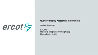
Resource Integration Small Generation Topics Process, Modeling, RARF, Reactive and AVR Testing Scenarios for DGRs / DESRs Zach Reich, P.E. ERCOT Resource Integration Working Group February 22, 2022
Topics: Small Generation DGR / DESR Timelines DGR / DESR Process and Flows DGR / DESR Simplified Modeling DGR / DESR Information in the RARF DGR / DESR Reactive Testing DGR / DESR AVR Testing 2
New Process for Small Generators TDSP Work Prior to RIOO Submittal (8 to 10 Months Timeline for Projects After the DGR Moratorium) 5/19/2022 Part 1 Approval 1/14/2022 Review required Submissions 1/31/2022 Registration RARF Approval 10/3/2021 Optional Small Gen Review Meeting 1/18/2022 Review RARF 5/31/2022 Part 2 Approval 1/4/2022 5/4/2022 PLD* 7/31/2022 Part 3 Approval Submit INR in RIOO 10/1/2021 8/1/2022 5/4/2022 - 7/31/2022 2/1/2022 - 5/1/2022 10/1/2021 - 1/1/2022 Commissioning Checklists & Testing Days RARF Submission (Prior to PLD) IE/RE Work with TDSP (IA, System Impact Studies, Interconnection Requirements, Operational Limitations, ETC) *Interim updates are not allowed for new units. Interim update requests must be approved by ERCOT Network Modeling. Construction time for TSP/DSP to construct needed facilities not shown. Start of construction dependent on RE giving TSP Notice to Proceed and providing the Funding to construct the interconnection facilities. Length of time needed for construction depends on facilities being constructed. The PLD shown above is normally after completion of construction. RE should have all TSP/DSP studies and IA complete before requesting the scoping meeting. 4
New Process for Small Generators RIOO Submittal Prior to TDSP Work (8 to 10 Months Timeline for Projects after DGR Moratorium) 8/27/2022 Part 1 Approval 4/30/2022 Registration RARF Approval 4/1/2022 1/9/2022 Optional Small Gen Review Meeting Submit required Submissions 4/14/2022 Review required Submissions 9/5/2022 Part 2 Approval 1/4/2022 8/3/2022 PLD* 4/18/2022 Review RARF Submit INR in RIOO 10/31/2022 Part 3 Approval 1/4/2022 11/1/2022 1/4/2022 - 4/1/2022 8/3/2022 - 11/1/2022 5/1/2022 - 8/1/2022 IE/RE Work with TDSP Commissioning Checklists & Testing Days RARF Submission (Prior to PLD) IE/RE Work with TDSP (IA, System Impact Studies, Interconnection Requirements, Operational Limitations, ETC) *Interim updates are not allowed for new units. Interim update requests must be approved by ERCOT Network Modeling. Construction time for TSP/DSP to construct needed facilities not shown. Start of construction dependent on RE giving TSP Notice to Proceed and providing the Funding to construct the interconnection facilities. Length of time needed for construction depends on facilities being constructed. The PLD shown above is normally after completion of construction. RE should have all TSP/DSP studies and IA complete before requesting the scoping meeting. 5
DGR and SOG Process Combined Note: This Small Gen process also includes Settlement Only Generators (SOG)s. The distinction between the DGRs and the SOGs is denoted by the dotted lines and red boxes with white text (See below): (Magnified representation) P.G. 5.1.1 - Applicability 6
Examples for Applicability (Initial Interconnection) 1MW- 10MW Small Generator Process Small Generator 10 MW Large Generator Large Generator Process 7
Examples for Applicability (Modification Interconnection) 1MW- 10MW <10MW <10MW Modification Small Generator Process Small Generator Small Generator 10 MW 1MW- 10MW <10MW Modification Small Generator Large Generator Process Large Generator 10 MW 10MW Modification 1MW- 10MW Small Generator Large Generator Large Generator Process 8
Examples for Applicability (Modification Interconnection) 10 MW 10 MW <10 MW Modification Small Generator Process Large Generator Large Generator 10 MW 10 MW 10MW Modification Large Generator Large Generator Large Generator Process 9
NPRR1026 and PGRR081 Self Limiting Facility (Not Implemented Yet) Self- Limiting Small Generator Self- Limiting Large Generator Self-Limiting Facility s established limit on the total MW Injection 1MW- <10MW, SOG <10MW Small Generator Process Small Generator DGR/DESR/GR/ESR 10 MW Large Generator Process Large Generator DGR/DESR/GR/ESR 10
NPRR1026 and PGRR081 Self Limiting Facility (Not Implemented Yet) <10MW, SOG <10MW 1MW- 1MW- <10MW, SOG <10MW <10MW Modification Self-Limit Small Generator Process Small Generator Small Generator DGR/DESR/GR/ ESR 10 MW 1MW- <10MW, SOG <10MW <10MW Modification Self-Limit Large Generator Process Large Generator Small Generator DGR/DESR/GR/ ESR Self-Limiting Facility s established limit on the total MW Injection 10 MW 1MW- <10MW, SOG <10MW 10MW Modification Self-Limit Small Generator DGR/DESR/GR/ ESR Large Generator Large Generator Process 10 MW 10 MW <10 MW Modification Self-Limit Small Generator Process Large Generator Large Generator DGR/DESR/GR/ ESR 10 MW 10 MW 10MW Modification Self-Limit Large Generator DGR/DESR/GR/ ESR Large Generator Large Generator Process 11
Old DGR Modeling Topology (Example) DGR / DESR Station TDSP Station Transmission Network Generating Unit TDSP Modeling Responsibility RE Data responsibility (RARF) DGR Line 13
Current DGR Modeling Topology Transmission Network Unit EPS Meter RE Data responsibility (RARF) Generating Unit DGR ERCOT s SE will zero-out these flows. 14
Current Multiple DGR Modeling Topology Transmission Network DGR #3 EPS Meter DGR #1 EPS Meter DGR #2 EPS Meter RE Data responsibility (RARF) DGR #2 DGR #3 DGR #1 Generating Unit(s) 15
End State DGR Status: All DGRs modeled/reflected on the transmission side of the CIM load. RE Role: Submit Service Requests to register new transmission connected DGRs. Submit Service Requests or RIOO-RS RSCRs to make updates to existing DGRs. TDSP Role: Provide EPS meter information. ERCOT Role: Model DGRs. 16
RARF Data Requirements Transmission Form: Only fill out Station tab information USE TDSP STATION CODE as no new Site is created Still include one-lines and transformer test reports Get Lat/Long information from TDSP Put 0.1 ohms as grounding resistance (placeholder value) All other tabs are to be LEFT BLANK! 18
RARF Data Requirements Gen Form: Impedance needs to reflect equivalent impedance of entire generating unit Does not have pad-mount step up transformer data and Gen Unit-Battery- inverter-transformer configuration Transformer impedance derived from test report or word document which is not part of RARF data. Estimated based on one-line POI Information is based on the TDSP Station Code. Voltage level is transmission level voltages Impedance base will be based off the MVA Nameplate values and the MV voltage levels. For the RARF, the Unit Generating Voltage can be at the MV level at Nameplate MVA For the Model, impedances will first be calculated using MV level and a Nameplate MVA base, then it will be converted to transmission voltage levels (On a 100MVA base) and be entered into the Model by ERCOT 19
RARF Data Requirements Load Resource Form: Dispatch asset code is the next asset code in the model (LD1, LD2, ETC). Get this from the TDSP. Voltages will all be transmission level voltages Station POD is TDSP Station Code Assign a descript description for the Load name 20
RARF Data Requirements Example Control Modes Reactive Capability Unity PF Control Mode: Reactive Capability Voltage Control Mode: 21
Equivalent impedance example ? ?? 11 ??? ? ?? 2.75 ??? Module1 R=0.02 p.u. X=1.02 p.u. R=0.08 p.u. X=4.08 p.u. ???????1= ?????????1 Module2 R=0.02 p.u. X=1.02 p.u. R=0.08 p.u. X=4.08 p.u. ???????2= ?????????2 Module3 R=0.02 p.u. X=1.02 p.u. R=0.08 p.u. X=4.08 p.u. ???????3= ?????????3 Module4 R=0.02 p.u. X=1.02 p.u. R=0.08 p.u. X=4.08 p.u. ???????4= ?????????4 22
Equivalent impedance example contd Test Step-up Transformer Specifications Voltage Low Side: 0.5 kV High (MV) Side: 12.5 kV MVA ratings: 2.75 MVA Positive sequence impedances: 6% Zero sequence impedance: 5% X/R: 10 Available Taps: 5 ( 2 x 3%) ???= 6% 11 2.75 ???= ??? sin tan 1?/? =6% sin tan 110 4 = 0.23881 ?.?. 11 2.75 ???= ??? cos tan 1?/? =6% cos tan 110 4 = 0.023881 ?.?. 23
Equivalent impedance example contd ??1= ???1+ ???????1 ??1= 0.08 + 0.023881 = 0.103881 ?.?. ??1= 4.08 + 0.23881 = 4.31881 ?.?. ??2= ???2+ ???????2 ??1= 0.08 + 0.023881 = 0.103881 ?.?. ??1= 4.08 + 0.23881 = 4.31881 ?.?. ??3= ???3+ ???????3 ??1= 0.08 + 0.023881 = 0.103881 ?.?. ??1= 4.08 + 0.23881 = 4.31881 ?.?. ??4= ???4+ ???????4 ??1= 0.08 + 0.023881 = 0.103881 ?.?. ??1= 4.08 + 0.23881 = 4.31881 ?.?. 24
Equivalent impedance example contd ???= ??1 ??2 ??3 ??4 ???= ??? + ???? 1 ???????????= Assumptions: 1 1 1 1 ??1+ =0.103881 ??2+ ??3+ ??4 = 0.02597 ?.?. 1. The impedances of all transformer-inverter- battery modules have the same MVA base. 2. The equivalent impedances of all transformer-inverter-battery modules have the same R/X ratios. 4 1 ???????????= 1 1 1 1 ??1+ =4.31881 ??2+ ??3+ ??4 = 1.0797 ?.?. 4 Note: Final Z (R and X components) calculations vary depending on MVA base and kV bases. 25
Equivalent impedance example contd End Result: DGR For example, here s an 11 MVA project Nameplate with a MV rating of 12.5 kV, and a transmission voltage level of 138 kV) For the RARF, the Unit Generating Voltage can be at 12.5 kV at 11 MVA For the Model, impedances will first be calculated using 12.5 kV and an 11 MVA base, then it will be converted to 138 kV 100MVA base and be entered into the Model by ERCOT staff 26
Reactive Testing Update for DGRs that are <20 MVA If TDSP specifies to maintain unity power factor Fill out reactive form in NDCRC (Put 0 or .1 MVAr for all CURL values) Attach TDSP Document requiring unity power factor to NDCRC RARF CURL and NDCRC CURL and other parameters all zero s This allows ERCOT to document that no test was done and why for the 5-year requirement to retest Otherwise, RARF and NDCRC CURL values to show reactive power output Fill out reactive form in NDCRC (Put actual MVAr values for CURL) Reactive test will validate CURL Reactive test can either follow current procedure or the grey box language if RE prefers that 28
ESR/BESS DGR - AVR Testing Objectives The purpose of the AVR test is to test the BESS s ability to go from full charge to full discharge while the AVR keeps the reactive power to as close as possible to 0 MVAr for a Unity power factor controlled AVR test at the Point of Interconnection (POI) or within the voltage specifications of the TDSP for a Voltage controlled AVR test. Keep voltage flicker at the POI to less than 1%, 2% or 3% depending on the frequency of voltage dips Minimize MVAR transients to the POI AVR test data will be entered on an Excel worksheet in 4 second time intervals. Column A is for the time-stamp (CST). Column B is for POI kV, Column C is for MW flow at the POI (+ for flow from the BESS to the POI). Column D is for MVAr flow at the POI (+ for flow from the BESS to the POI).
Voltage Setpoint for AVR test For Unity Power Factor Control DGR / DESR During the AVR test, measurements must be taken and recorded at each the following MW levels: 100% charging 75% charging 50% charging 25% charging 0% charging/discharging 25% discharging 50% discharging 75% discharging 100% discharging Allow MW output to settle for each scenario 100% Discharging 75% Discharging 50% Discharging 25% Discharging MW 0 100% Charging 50% Charging 75% Charging 25% Charging Coordinate test with ERCOT and DSP and/or TSP Report data in 4 second intervals t
Example of MVAr Transients: These occur mostly during changes from 0 to charging/discharging and need to be kept to a minimum Switching Transients
PASS/FAIL Criteria (Without Taking Transients Into Consideration): Each test point is evaluated using three test criteria: For when abs(BESS MW POI flow) is >= 30% of maximum MW BESS capability A test measurement will pass if the abs(BESS MVAr POI flow) is <= 3.5% of abs(BESS MW POI flow) For when abs(BESS MW POI flow) is < 30% of maximum MW BESS capability A test measurement will pass ifthe abs(BESS MVAr POI flow) is <= 1.3% of the BESS MW capability or 130KVAr (which ever is higher, see below) A test measurement will pass if the MVAr flow at the POI is less than X as follows 12.47 kV, X = 0.130 MVAr 24.9 kV, X = 0.170 MVAr 34.5 kV, X = 0.200 MVAr
Overall AVR Test Evaluation: Overall to pass the ERCOT AVR test, the test points must pass one of the above three criteria, OR For the test points that fail the above 3 criteria, the voltage dips must be less than the following. (to minimize MVAR transients to the POI) Voltage dips resulting in a <= 3% change in POI voltage will pass if the frequency of voltage dips is <= 10 voltage dips per hour (for typical operations) Voltage dips resulting in a <= 2% change in POI voltage will pass if the frequency of voltage dips is <= 1 voltage dip per minute (for typical operations) Voltage dips resulting in a <= 1% change in POI voltage will pass if the frequency of voltage dips is <= 15 voltage dips per minute (for typical operations) ERCOT will consult DSP/TSP if there is a question of the AVR Test passing
PASS/FAIL Criteria: This is a visualization for a 10 MW DGR/ESR as an example: A test measurement will pass if the MVAr flow at the POI is less than X as follows: 12.47 kV, X = 0.130 MVAr 24.9 kV, X = 0.170 MVAr 34.5 kV, X = 0.200 MVAr NOTE: This curve is duplicated for ( ) MVAR as well
Voltage Setpoint for AVR Voltage Control test For DGR ESR/BESS Coordinate test with ERCOT and TDSP Report data in 4 second intervals or smaller Exceptions to 3% step requirement: If a 3% step will cause the voltage to exceed 1.05 p.u. or drop below 0.95 p.u. The TDSP has placed additional restrictions on the voltage setpoint Don t violate any DSP or TSP restrictions Acceptance Criteria is on a case by bases based on agreements between the RE and TDSP Allow voltage to settle Return to original 3% step up setpoint kV Return to original 3% step down setpoint Allow voltage to settle t
AVR Voltage Control Example: There is no KVT or KVM mapping currently, so the voltage instructions are given manually and verbally. leading/lagging reactive capabilities, to maintain voltage at the Point of Common Coupling (PCC) to the target setpoint. While in AVR control mode, sites will automatically adjust reactive power, up to their maximum The acceptance criteria is specified by each TDSP and validated by ERCOT If the target voltage needs to be temporarily adjusted, the following process should be followed. Entity requesting change must contact other entity via phone call to operations control room and communicate the new desired voltage setpoint. If requesting entity is, o TDSP: 1. RE will confirm feasibility of requested voltage setpoint based on unit availability/capability. 2. RE remote operator will then manually adjust voltage target within the respective site controller. 3. Voltage target will remain in place until manually readjusted. Steps 1 and 2 must be repeated to revert to initial target. RE: 1. TDSP will confirm feasibility of requested voltage setpoint based on system conditions. 2. RE remote operator will then manually adjust voltage target within the respective site controller. 3. Voltage target will remain in place until manually readjusted. Steps 1 and 2 must be repeated to revert to initial target. o 37
Other contact information ResourceIntegrationDepartment@ercot.com is distribution list for Resource Integration department Mailing List RESOURCE_INTEGRATION@LISTS.ERCOT.COM 38
Questions? Thank you!


")
")
")


")