Volvo BM A30C BMA30C Articulated Dump Truck Service Repair Manual Instant Download
Please open the website below to get the complete manualnn// n

Download Presentation

Please find below an Image/Link to download the presentation.
The content on the website is provided AS IS for your information and personal use only. It may not be sold, licensed, or shared on other websites without obtaining consent from the author. Download presentation by click this link. If you encounter any issues during the download, it is possible that the publisher has removed the file from their server.
E N D
Presentation Transcript
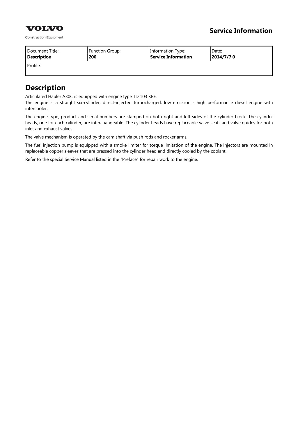
Service Information Document Title: Description Function Group: 200 Information Type: Service Information Date: 2014/7/7 0 Profile: Description Articulated Hauler A30C is equipped with engine type TD 103 KBE. The engine is a straight six-cylinder, direct-injected turbocharged, low emission - high performance diesel engine with intercooler. The engine type, product and serial numbers are stamped on both right and left sides of the cylinder block. The cylinder heads, one for each cylinder, are interchangeable. The cylinder heads have replaceable valve seats and valve guides for both inlet and exhaust valves. The valve mechanism is operated by the cam shaft via push rods and rocker arms. The fuel injection pump is equipped with a smoke limiter for torque limitation of the engine. The injectors are mounted in replaceable copper sleeves that are pressed into the cylinder head and directly cooled by the coolant. Refer to the special Service Manual listed in the "Preface" for repair work to the engine.
Service Information Document Title: Method engine speed (rpm) Function Group: 214 Information Type: Service Information Date: 2014/7/7 0 for measuring Profile: Method for measuring engine speed (rpm) Op nbr 00000 Electronic pulse and engine speed (rpm) gauge Moviport C 117.11 (Braun GmdH) Photo-probe A 1S 30P Extension cable SAK Marking tape Magnetic stand with extension arm Transmission and hydraulic system must be at normal operating temperature when checking the engine speed. During engine speed check, all components with large electric power consumption and eventual air conditioning unit must be turned off and made non-operational. NOTE! This is an alternative method to be used when the service display unit is not available, see Section 4. 1. Open the engine hood. 2. Figure 1
Measuring engine speed (rpm) 1. 2. 3. 4. 5. Marking tape Magnetic stand with extension arm Photo-probe A 1S 30P Extension cablel SAK Electronic pulse and engine speed (rpm) gauge Moviport C 117.11 (Braun GmdH) Connect the measuring equipment according to fig. Clean and attach a piece of marking tape to the crankshaft pulley. Attach the magnetic stand with the extension arm and photo-probe on the frame. Aim the photo probe at the marking tape. Connect the extension cable between the photo-probe and the engine speed (rpm) gauge. Start the engine and read off the engine speed reading (rpm) on instrument in the cab. CAUTION When using this method, read the engine speed directly off the engine speed (rpm) gauge on the instrument panel in the cab. Avoid sudden forceful movements against the pulley.
https://www.ebooklibonline.com Hello dear friend! Thank you very much for reading. Enter the link into your browser. The full manual is available for immediate download. https://www.ebooklibonline.com
Service Information Document Title: Valves, adjusting Function Group: 214 Information Type: Service Information Date: 2014/7/7 0 Profile: Valves, adjusting Op nbr 21412 999 3590C Gear wheel 1. Open the engine hood. 2. Clean around the valve covers, loosen and remove them. 3. Remove the plug on the flywheel housing and attach tool, see fig. Figure 1 1. Gear wheel 3590 is positioned in the hole of the flywheel housing. Use a standard ratchet handle that can be combined with a universal joint and an extension piece from a 1/2 inch socket wrench set. Inspection hole for flywheel markings. 2. WARNING The stop control must be secured in the stop position, ignition key in the "0'' position and the engine must be cold to eliminate the risk of the engine starting. The crankshaft must be turned slowly and carefully. 4. Rotate the flywheel in the correct direction until nr.1 piston is at T.D.C. after the compression stroke (0 on the flywheel markings). Adjust valves 1, 2, 4, 5, 8 and 9. Inlet valve clearance should be 0.40 mm (0.015 in) and exhaust valve clearance should be 0.70 mm (0.027 in) when engine is cold. Valve positions, see fig.
Figure 2 Valve positions (top view of engine) Inlet valve Exhaust valve 5. Rotate the flywheel another full turn in the correct rotational direction until nr.6 piston turns aroud after compression stroke. Adjust valves 3, 6, 7, 10, 11, 12. CAUTION Valve adjustments must not be done with the engine running since the valves may knock the piston and cause serious damage. 6. Remove the gear wheel from the flywheel housing. 7. Replace the valve covers and tighten valve cover bolts. Start and run the engine to check function, close the engine hood.
Service Information Document Title: Description Function Group: 220 Information Type: Service Information Date: 2014/7/7 0 Profile: Description The engine is pressure lubricated by an oil pump driven by a crankshaft and gear. The oil pump is a double-pump. The front main pump supplies the lubrication system with oil. The rear pump transports oil from the oil sump rear section to the front section to ensure that the main pump receives oil during operation on steep uphill grades. The main pump forces the oil by way of the oil cooler, both full-flow filters and the engine block oil passages to all points of lubrication. There are four valves in the lubrication system: 1. 2. The reduction valve opens at an oil pressure exceeding the norm, and directs surplus oil back to the oil sump. The by-pass valve opens when the pressure drop across the oil cooler is too high, i.e. during a cold-start. When the valve opens, the oil flows past the oil cooler and reaches all engine lubrication points faster. The engine oil cooler is mounted on the oil filter bracket. The overflow valve for the oil filters opens if the filters are clogged and ensures a constant oil supply for sufficient lubrication. The piston cooling valve opens when the engine speed has increased to just above idle, when the oil pressure has increased and the oil is directed by way of a groove to the piston cooling passage in the engine block. There are six inlets connected to the piston cooling passage, one for each piston, and oil is sprayed from the inlets on the underside of the pistons. 3. 4. There is an extra oil filter on the left side of the engine. It is a partial-flow filter with low flow-through but with high filtering capacity. Figure 1 1. 2. 3. 4. Reduction valve By-pass valve for oil cooler Overflow valve for oil filters Piston cooling valve
Service Information Document Title: Bleeding of fuel system Function Group: 230 Information Type: Service Information Date: 2014/7/7 0 Profile: Bleeding of fuel system The fuel system must be bled if the machine has been operated until it has run out of fuel (fuel tank dry) or the tank has been emptied for other reasons. CAUTION No attempts to start the engine must be made prior to bleeding the fuel system since the fuel injection pump may be severly damaged! Figure 1 A Bleeding screw B Manual pump C Pressure lines Proceed as follows: Loosen the bleeding screw (A) on the top of the filter. Using a manual handpump, continue to pump until fuel runs out and is free of air bubbles. Tighten the bleeding screw. Pump approximately 15 full pumps using the handpump (B). The fuel injection pump is automatically through the overflow valve and the return oil line.
Loosen the pressure lines (C) by the injectors and run the starter motor until fuel rushes out and is free from air bubbles. CAUTION The pressure lines are pre-formed to withstand high pressures and must never be bent or altered in any way! Tighten connections of the pressure lines. CAUTION Do not tighten too hard, the threads can be damaged. The engine can now be started. After starting the engine, check to make sure that there are no leaks. WARNING Make sure that fuel under high pressure does not come in contact with unprotected body parts during work with fuel injection equipment.
Service Information Document Title: Fuel checking Function Group: 233 Information Type: Service Information Date: 2014/7/7 0 feed pressure, Profile: Fuel feed pressure, checking Op nbr 23304 999 3335 Hose E 965 Nipple Pressure gauge, range 0 250 kPa (0 2.5 bar) (0 36.3 psi) 1. Connect pressure gauge according to fig 10 and check fuel feed pressure with engine running at low idle. Correct feed pressure 130 80 kPa (1.3 1.8 bar) (18.9 26.1 psi). Figure 1 Measuring fuel feed pressure 1. 2. 3. Pressure gauge Hose 999 3335 Nipple E 965
Service Information Document Title: Automatic timing adjuster, checking Function Group: 236 Information Type: Service Information Date: 2014/7/7 0 Profile: Automatic timing adjuster, checking Op nbr 23631 999 3721 Service display unit 999 3590 Gear wheel 11 668 003 Measuring instrument Measuring instrument 11 668 003 consists of electronic unit, cabling and two sender units. The sender units sense the difference between a groove in the transmission converter, showing when cylinder number 1 passes top dead center (T.D.C.), and a camber in the injection pump regulator housing, which shows the position of the pump cam shaft when fuel injection begins on cylinder 1. Read off on service display unit 999 3721.
1. Figure 1 A Cigarette lighter socket Open the engine hood. Remove metal plate plug 1 and upper rubber plug 2 on the flywheel housing, see fig.
Figure 2 2. Check that the engine is not in the area of 0 20 B.T.D.C. This is to make sure that the sender unit in the flywheel housing does not end up in front of the measuring groove in the transmission converter during adjustment. (If the engine needs to be cranked, mount gear wheel in hole 1, see fig.) 3. Swing out the radiator. 4. Mount sender unit in the flywheel housing. Carefully screw it in up against the converter, turn back one full turn and lock it with a locking nut, see fig. Figure 3 A Sender unit 5. Mount sender unit in the fuel pump regulator housing. Be prepared with a suitable container to collect the oil that drains, approx 0,3 L (0,08 US gals). 6. Connect sender units, electronic unit and the service display unit. Switch on the current according to fig. 7. Start display appears for approximately four seconds. Figure 4 8. The adjoining display is shown.
Figure 5 9. Start the engine. If sender units are operating correctly, the adjoining display is shown. Go on to step 12. Figure 6 10. If fuel pump sender unit is not operational, the adjoining display is shown. Figure 7 11. If the sender unit in the transmission housing is not operational or it is not turned out one full turn from the converter, the adjoining display is shown. Figure 8 12. If senders are operational, push key The adjoining display is shown. Figure 9
13. Push key Example is shown by adjoining display. for register first value. Figure 10 14. Increase engine speed to 1100 rpm and push key Example is shown by adjoining display. Figure 11 15. Increase engine speed to 1400 rpm and push key Example is shown by adjoining display. Figure 12 16. Increase engine speed to 2100 rpm and push key Example is shown by adjoining display. Maximal angle adjustment should now be complete. The adjustment shall be 6 1 and is checked by calculating the difference between the highest and the lowest value. In the example, -0,7 to 5,1 =5,8 . The negative value is due to the disappearance of clearance in the fuel pump drive gear during load application. Push key to reset the service display unit to prepare for a new set of measurements. Figure 13
17. Remove the electronic unit, service display unit and the two sender units. Swing the radiator back into operating position. Mount the metal plate plug and the rubber plug in the flywheel housing and close the engine hood.
Service Information Document Title: Fuel (Injection timing), checking and adjusting Function Group: 236 Information Type: Service Information Date: 2014/7/7 0 injection angle Profile: Fuel injection angle (Injection timing), checking and adjusting Op nbr 23630 999 3590 Gear wheel 998 7057 Measuring instrument WARNING The stop control must be secured in the stop position and the engine must be cold to eliminate the risk of the engine starting. The crankshaft must be turned slowly and carefully. Checking 1. Remove valve cover from cylinder nr 1. 2. Remove the metal plate plug (1) and the upper rubber plug (2) from the flywheel housing, see fig. Figure 1 1. Turning the crankshaft Gear wheel 3590 is positioned in the hole of the flywheel housing. Use a standard ratchet handle that can be combined with a universal joint and an extension piece from a 1/2 inch socket wrench set. Drive disc markings 2. 3. Attach gear wheel 3590 and turn the flywheel until cylinder nr\x111 is in compression stroke (0 marking on the
drive disc and valves closed). Figure 2 4. Remove the plug in the regulator housing and attach the measuring instrument sender unit. Secure ground cable to machine frame in suitable position. CAUTION Regulator housing contains oil. Figure 3 5. Reverse the engine 1/4 turn and then crank the engine in the rotational direction until both lights on the measuring instrument are lit. Note degree reading on the drive disc. The reading should be 9 B.T.D.C.
Suggest: If the above button click is invalid. Please download this document first, and then click the above link to download the complete manual. Thank you so much for reading
Figure 4 6. If the engine is cranked too far, repeat procedure from step 5. 7. Remove the measuring instrument. Replace plugs and the valve cover. Adjusting 8. Turn in the rotational direction of the engine until correct degree marking appears on the drive disc. 9. Attach measuring instrument in the regulator housing. See Injection timing, checking. 10. Loosen the clamping bolt on the pump coupling (fig.) and turn the pump drive shaft 1/4 turn in the pump rotational direction (fig). Figure 5
https://www.ebooklibonline.com Hello dear friend! Thank you very much for reading. Enter the link into your browser. The full manual is available for immediate download. https://www.ebooklibonline.com


")


 by the injectors and run the")


.")