Introduction to Air Brakes for Combination Units

 
Intro to air brakes for combination units
 
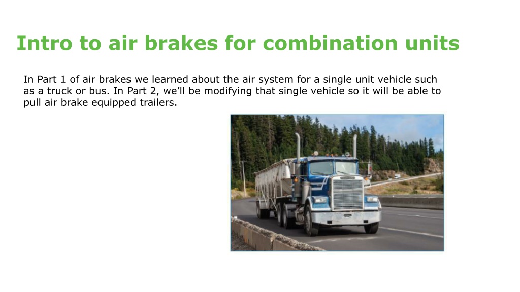
In Part 1 of air brakes we learned about the air system for a single unit vehicle such
as a truck or bus. In Part 2, we’ll be modifying that single vehicle so it will be able to
pull air brake equipped trailers.
 
Air brakes valves for combination units
 
To convert a truck to a tractor (and be able to tow a trailer) we must add these key valves.
Note that this is not a complete list of valves.
 
Trailer control valve -
generally a red button
inside the cab.
 
Tractor protection valve.
 
Air lines and gladhands -
to deliver the air to the
trailers to be towed.
 
Also an optional valve
commonly found in trucks -
a hand valve to control the
service brakes on the trailer
independently from the foot
valve.
undefined
 
Air brakes components added
 
This diagram shows two service reservoirs, the dual foot valve, and the
components that are added to a tractor with a dual air system to tow a trailer
with air brakes.
 
3
undefined
 
Failure in primary system
 
This diagram shows a tractor with a dual air system where there has been a
failure in the primary air system on the tractor.
 
4
undefined
 
Air brake valves working together
 
This diagram shows how the tractor protection valve and the trailer air supply
valve act together.
 
5
undefined
 
Bobtailing
 
Driving a tractor without a trailer attached is
called bobtailing.
Because a bobtail tractor has very little weight
over the rear drive axles, it’s very easy to lock up
the rear brakes, even with a light brake
application.
To help prevent this unwanted lockup and to
increase control, some tractors are equipped with
a 
bobtail proportioning system
.
 
6
undefined
 
Trailer system components
 
A trailer system has many of the components found on a truck system:
 
foundation brakes
air chambers
air reservoirs
control valves
 
The only major item not found on a trailer air system is an air compressor.
Air for the trailer must come from the tractor.
 
7
undefined
 
Air brakes trailer components cont.
 
There are two air line connections
between the tractor and the trailer:
The air line that supplies the trailer
reservoirs with air at full tractor
reservoir pressure is called the 
supply
line
, or the 
emergency line
.
The line that carries the control signal
from the tractor is called the 
control
line 
or commonly called the 
service
line
.
 
8
undefined
 
Air brakes trailer air system
 
There are two types of trailer air systems — those that use spring parking
brakes and those that don’t.
Although most current trailers use spring parking brakes, some older trailers
and converter dollies aren’t equipped with spring parking brakes.
 
9
undefined
 
Trailer with spring parking brakes — charging
 
This
 
diagram
 
shows
 
a
 
typical
 
trailer
 
system
 
that
 
uses
 
spring
 
parking
 
brakes
 
for 
parking and for
emergency (breakaway)
 
stopping.
 
10
undefined
 
Air brakes trailer spring brake valves
 
The tractor is delivering air through the supply line to the trailer spring brake valve.
The spring parking brake valve directs air to fill the reservoir(s) and to release the
spring parking brakes.
 
11
undefined
 
Trailer with spring parking brakes — service brake application
 
In this diagram, a control signal from the tractor has been sent through the
control line to the trailer’s relay valve.
 
12
undefined
 
Trailer with spring parking brakes — dynamited
 
This diagram shows a ruptured supply line
 
13
undefined
 
Braking combination units
 
When making a foot valve brake application, there will be an
equal amount of air supplied to the service brakes on the tractor
and the trailer.
If an application is made with the foot and a greater one with the
hand valve, the service brakes on the trailer will be applied with
more force.
 
14
undefined
 
Trailer ABS air brake systems
 
Trailer ABS systems use similar components as
those on trucks and tractors The ECU may be
powered from the stop lamp circuit, or may have
a dedicated power source through the electrical
connector.
Trailers with ABS air brakes will also have an
indicator visible in the tractor’s mirror to indicate
if the system’s not functioning properly. This
warning light may be mounted on the front left
side of the trailer or on the rear left side of the
trailer.
 
15
 
On some air brake systems, there may be a trailer ABS warning indicator on the dashboard of
the tractor.
undefined
 
Combination unit air pre-trip
 
On the following slides, we’ll
go over the steps to perform
a pre-trip on a tractor-trailer
unit.
You’ll notice that much of the
information is the same as the
single unit.
 
16
undefined
 
Getting started
 
17
 
Before getting started:
 
make sure you’re safe and seen
block the wheels and
place the transmission in low gear.
 
undefined
 
Reservoirs
 
Check to see if you have some
air on the air gauges.
Drain the supply tank (wet
tank) if equipped.
Recheck the gauges to see if
the air in the reservoirs
remained the same.
This confirms the one-way
check valve is working.
 
18
undefined
 
Under the hood – foundation brakes
 
Open the hood and check the travel
of the slack adjustor.
Check the air line coming out to the
brake chamber for cracks or damage.
Check the brake chamber to ensure it
is in good condition and secure.
Repeat this on both sides.
 
19
undefined
 
Under the hood - compressor
 
Check the compressor to ensure it is
secure and the discharge line (the main
line of the compressor) is in good
condition.
Check that all other air lines under the
hood are secure and in good condition.
Check that there are no coolant or oil
leaks.
 
20
undefined
 
In cab
 
Get into the truck, confirm the vehicle is in neutral, and start the engine.
Release the brakes by pushing in the yellow and red button.
 
21
undefined
 
In cab – check governor operation
 
Press and release the brake pedal (called fanning
down) to lower the air no lower then 80 psi. Allow the
compressor to build to maximum air pressure
between 105-135.
Next, lower the air 20 psi to confirm the governor
puts the compressor into the reload stage. This will
be determined when the needles begin to climb.
Continue to lower the air pressure further by fanning
down to check the low air warning. It must come on
by 60 psi.
 
22
 
Continue to lower the air pressure until the trailer supply valve closes.  This must
happen between 45-20 psi.
Exit the cab and confirm the trailer parking brake circuit has engaged.
undefined
 
Check parking brake on trailer is engaged
 
Walk to the rear of the trailer to visually check that the push rods have
extended, engaging the parking brake circuit.
 
23
undefined
 
Disconnect air lines
 
Return to the front of the
trailer and disconnect the air
lines.
 
24
undefined
 
Check tractor protection valve
 
Once the air lines are
disconnected, make a brake
application to confirm that the
tractor protection valve is working.
This will be confirmed if there is no
air escaping from the air lines
while the brake pedal is being held.
 
25
undefined
 
Continue compressor check
 
Re-enter the cab to complete the
compressor check.
Start the engine and when the first needle
hits 50 psi start timing. The compressor
must build from 50 to 90 psi in under
three minutes at an rpm of 1000-1200.
Stop the timing when the last needle goes
through 90 psi.
 
26
 
Release the parking brakes, push the
trailer supply valve, and continue to build
to maximum air to confirm that the
governor puts the compressor into the
unload stage between 105 and 135 psi.
undefined
 
Start leak test
 
27
undefined
 
Leak test
 
With the brakes released, the engine off and the window open to hear
any audible air leaks, make a firm brake application.
To perform a leak test, hold a firm brake application for one minute.
After the initial application, the system must not lose any more then
four psi during that time with a single trailer and no more then six psi
with two trailers.
Listen out the window for any audible air leaks.
Once completed, confirm there’s a minimum of 100 psi in the
reservoirs and the brakes remained released.
Put the transmission in low gear and exit the vehicle.
 
 
28
undefined
 
Under tractor
 
Go under the rear of the vehicle to
check that air tanks are secure and
air lines are tied up and secure.
Then, move back to the rear wheels
to perform the same checks as at the
front.
 
29
undefined
 
Check air lines and pushrods
 
Check at each wheel that the air
lines going into the brake
chambers are in good condition,
the brake chambers are in good
condition, and that you have the
correct pushrod travel.
Use either the pry bar method or
the applied stoke method.
 
30
undefined
 
Apply the parking brakes
 
Exit from under the vehicle and apply the brakes by pulling the
yellow button.
 
31
undefined
 
Remove wheel blocks
 
Once the brakes are applied remove the wheel
blocks.
 
32
undefined
 
Four-way brake response test
 
Enter the vehicle and confirm the transmission is in neutral.
1.
Start the engine, place in low gear with the parking brakes applied on the
tractor and the trailer brakes released. Try to move the vehicle to confirm
the parking brakes are holding the tractor.
2.
Release the tractor parking brakes and apply the trailer parking brakes. Try
to move the vehicle to confirm the parking brakes are holding on the trailer.
3.
If yes, release the parking brakes on the tractor and trailer and allow the
vehicle to roll ahead. Using the foot valve make a brake application to
confirm the vehicle will stop.
4.
If it stops, again allow the vehicle to roll ahead. Using the hand valve (if
equipped) apply the service brakes on the trailer to confirm the vehicle
stops.
 
 
33
undefined
 
Adjusting a manual slack adjuster
Slide Note
Embed
Share

In this guide, we delve into the world of air brakes for combination units, specifically focusing on the modifications required to enable a single vehicle such as a truck or bus to pull air brake-equipped trailers. The content covers essential valves, components, failure scenarios, and operational aspects of air brake systems in combination units, providing valuable insights into tractor-trailer operation dynamics.


Uploaded on Aug 22, 2024 | 0 Views


Download Presentation

Please find below an Image/Link to download the presentation.

The content on the website is provided AS IS for your information and personal use only. It may not be sold, licensed, or shared on other websites without obtaining consent from the author. Download presentation by click this link. If you encounter any issues during the download, it is possible that the publisher has removed the file from their server.

E N D

Presentation Transcript


  1. Intro to air brakes for combination units In Part 1 of air brakes we learned about the air system for a single unit vehicle such as a truck or bus. In Part 2, we ll be modifying that single vehicle so it will be able to pull air brake equipped trailers.

  2. Air brakes valves for combination units To convert a truck to a tractor (and be able to tow a trailer) we must add these key valves. Note that this is not a complete list of valves. Trailer control valve - generally a red button inside the cab. Tractor protection valve. Also an optional valve commonly found in trucks - a hand valve to control the service brakes on the trailer independently from the foot valve. Air lines and gladhands - to deliver the air to the trailers to be towed.

  3. Air brakes components added This diagram shows two service reservoirs, the dual foot valve, and the components that are added to a tractor with a dual air system to tow a trailer with air brakes. 3

  4. Failure in primary system This diagram shows a tractor with a dual air system where there has been a failure in the primary air system on the tractor. 4

  5. Air brake valves working together This diagram shows how the tractor protection valve and the trailer air supply valve act together. 5

  6. Bobtailing Driving a tractor without a trailer attached is called bobtailing. Because a bobtail tractor has very little weight over the rear drive axles, it s very easy to lock up the rear brakes, even with a light brake application. To help prevent this unwanted lockup and to increase control, some tractors are equipped with a bobtail proportioning system. 6

  7. Trailer system components A trailer system has many of the components found on a truck system: foundation brakes air chambers air reservoirs control valves The only major item not found on a trailer air system is an air compressor. Air for the trailer must come from the tractor. 7

  8. Air brakes trailer components cont. There are two air line connections between the tractor and the trailer: The air line that supplies the trailer reservoirs with air at full tractor reservoir pressure is called the supply line, or the emergency line. The line that carries the control signal from the tractor is called the control line or commonly called the service line. 8

  9. Air brakes trailer air system There are two types of trailer air systems those that use spring parking brakes and those that don t. Although most current trailers use spring parking brakes, some older trailers and converter dollies aren t equipped with spring parking brakes. 9

  10. Trailer with spring parking brakes charging This diagram shows a typical trailer system that uses spring parking brakes for parking and for emergency (breakaway) stopping. 10

  11. Air brakes trailer spring brake valves The tractor is delivering air through the supply line to the trailer spring brake valve. The spring parking brake valve directs air to fill the reservoir(s) and to release the spring parking brakes. 11

  12. Trailer with spring parking brakes service brake application In this diagram, a control signal from the tractor has been sent through the control line to the trailer s relay valve. 12

  13. Trailer with spring parking brakes dynamited This diagram shows a ruptured supply line 13

  14. Braking combination units When making a foot valve brake application, there will be an equal amount of air supplied to the service brakes on the tractor and the trailer. If an application is made with the foot and a greater one with the hand valve, the service brakes on the trailer will be applied with more force. 14

  15. Trailer ABS air brake systems Trailer ABS systems use similar components as those on trucks and tractors The ECU may be powered from the stop lamp circuit, or may have a dedicated power source through the electrical connector. Trailers with ABS air brakes will also have an indicator visible in the tractor s mirror to indicate if the system s not functioning properly. This warning light may be mounted on the front left side of the trailer or on the rear left side of the trailer. On some air brake systems, there may be a trailer ABS warning indicator on the dashboard of the tractor. 15

  16. Combination unit air pre-trip On the following slides, we ll go over the steps to perform a pre-trip on a tractor-trailer unit. You ll notice that much of the information is the same as the single unit. 16

  17. Getting started Before getting started: make sure you re safe and seen block the wheels and place the transmission in low gear. 17

  18. Reservoirs Check to see if you have some air on the air gauges. Drain the supply tank (wet tank) if equipped. Recheck the gauges to see if the air in the reservoirs remained the same. This confirms the one-way check valve is working. 18

  19. Under the hood foundation brakes Open the hood and check the travel of the slack adjustor. Check the air line coming out to the brake chamber for cracks or damage. Check the brake chamber to ensure it is in good condition and secure. Repeat this on both sides. 19

  20. Under the hood - compressor Check the compressor to ensure it is secure and the discharge line (the main line of the compressor) is in good condition. Check that all other air lines under the hood are secure and in good condition. Check that there are no coolant or oil leaks. 20

  21. In cab Get into the truck, confirm the vehicle is in neutral, and start the engine. Release the brakes by pushing in the yellow and red button. 21

  22. In cab check governor operation Press and release the brake pedal (called fanning down) to lower the air no lower then 80 psi. Allow the compressor to build to maximum air pressure between 105-135. Next, lower the air 20 psi to confirm the governor puts the compressor into the reload stage. This will be determined when the needles begin to climb. Continue to lower the air pressure further by fanning down to check the low air warning. It must come on by 60 psi. Continue to lower the air pressure until the trailer supply valve closes. This must happen between 45-20 psi. Exit the cab and confirm the trailer parking brake circuit has engaged. 22

  23. Check parking brake on trailer is engaged Walk to the rear of the trailer to visually check that the push rods have extended, engaging the parking brake circuit. 23

  24. Disconnect air lines Return to the front of the trailer and disconnect the air lines. 24

  25. Check tractor protection valve Once the air lines are disconnected, make a brake application to confirm that the tractor protection valve is working. This will be confirmed if there is no air escaping from the air lines while the brake pedal is being held. 25

  26. Continue compressor check Re-enter the cab to complete the compressor check. Start the engine and when the first needle hits 50 psi start timing. The compressor must build from 50 to 90 psi in under three minutes at an rpm of 1000-1200. Stop the timing when the last needle goes through 90 psi. Release the parking brakes, push the trailer supply valve, and continue to build to maximum air to confirm that the governor puts the compressor into the unload stage between 105 and 135 psi. 26

  27. Start leak test 27

  28. Leak test With the brakes released, the engine off and the window open to hear any audible air leaks, make a firm brake application. To perform a leak test, hold a firm brake application for one minute. After the initial application, the system must not lose any more then four psi during that time with a single trailer and no more then six psi with two trailers. Listen out the window for any audible air leaks. Once completed, confirm there s a minimum of 100 psi in the reservoirs and the brakes remained released. Put the transmission in low gear and exit the vehicle. 28

  29. Under tractor Go under the rear of the vehicle to check that air tanks are secure and air lines are tied up and secure. Then, move back to the rear wheels to perform the same checks as at the front. 29

  30. Check air lines and pushrods Check at each wheel that the air lines going into the brake chambers are in good condition, the brake chambers are in good condition, and that you have the correct pushrod travel. Use either the pry bar method or the applied stoke method. 30

  31. Apply the parking brakes Exit from under the vehicle and apply the brakes by pulling the yellow button. 31

  32. Remove wheel blocks Once the brakes are applied remove the wheel blocks. 32

  33. Four-way brake response test Enter the vehicle and confirm the transmission is in neutral. 1. Start the engine, place in low gear with the parking brakes applied on the tractor and the trailer brakes released. Try to move the vehicle to confirm the parking brakes are holding the tractor. 2. Release the tractor parking brakes and apply the trailer parking brakes. Try to move the vehicle to confirm the parking brakes are holding on the trailer. 3. If yes, release the parking brakes on the tractor and trailer and allow the vehicle to roll ahead. Using the foot valve make a brake application to confirm the vehicle will stop. 4. If it stops, again allow the vehicle to roll ahead. Using the hand valve (if equipped) apply the service brakes on the trailer to confirm the vehicle stops. 33
  34. Adjusting a manual slack adjuster

Related


More Related Content

giItT1WQy@!-/#giItT1WQy@!-/#giItT1WQy@!-/#giItT1WQy@!-/#