Volvo A40F FS A40FFS Articulated Dump Truck Service Repair Manual Instant Download
Please open the website below to get the complete manualnn// n

Download Presentation

Please find below an Image/Link to download the presentation.
The content on the website is provided AS IS for your information and personal use only. It may not be sold, licensed, or shared on other websites without obtaining consent from the author. Download presentation by click this link. If you encounter any issues during the download, it is possible that the publisher has removed the file from their server.
E N D
Presentation Transcript
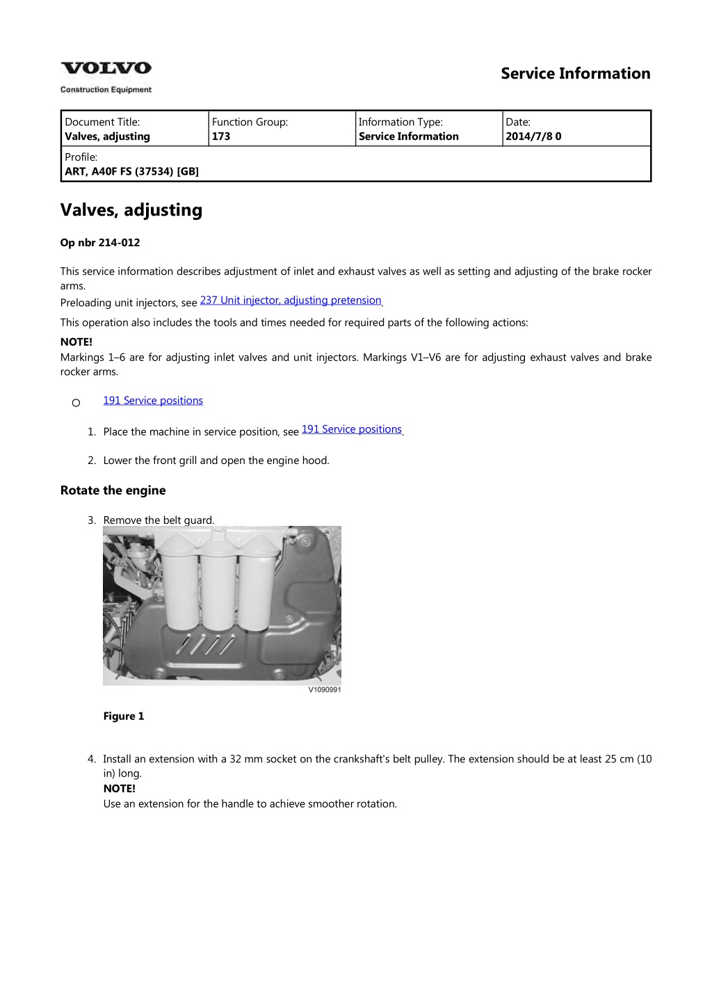
Service Information Document Title: Valves, adjusting Function Group: 173 Information Type: Service Information Date: 2014/7/8 0 Profile: ART, A40F FS (37534) [GB] Valves, adjusting Op nbr 214-012 This service information describes adjustment of inlet and exhaust valves as well as setting and adjusting of the brake rocker arms. Preloading unit injectors, see This operation also includes the tools and times needed for required parts of the following actions: NOTE! Markings 1 6 are for adjusting inlet valves and unit injectors. Markings V1 V6 are for adjusting exhaust valves and brake rocker arms. 237 Unit injector, adjusting pretension . 191 Service positions 191 Service positions 1. Place the machine in service position, see . 2. Lower the front grill and open the engine hood. Rotate the engine 3. Remove the belt guard. Figure 1 4. Install an extension with a 32 mm socket on the crankshaft's belt pulley. The extension should be at least 25 cm (10 in) long. NOTE! Use an extension for the handle to achieve smoother rotation.
Figure 2 5. Remove the valve cover. 6. Loosen the bolts for the brake rocker arms' leaf springs. Leave the leaf springs in place. Figure 3 7. Rotate the engine in its rotational direction (clockwise) until the nearest line marking on the camshaft stands between the marks on the bearing cap. NOTE! Markings 1 6 are for adjusting inlet valves and unit injectors. Markings V1 V6 are for adjusting exhaust valves and brake rocker arms.
Figure 4 Figure 5 Cylinder number Inlet valves, checking and adjusting 8. Check that the valve clearance between the yoke and rocker arm's thrust sleeve is according to . If needed, adjust as follows: Adjust correct valve clearance for the inlet valves. Place a tool in adjusting screw B as counterhold and tighten lock nut A with a box-end wrench. See Recheck the valve clearance. NOTE! Using a marking pen, mark when adjusting is done to keep track of which valves, unit injectors, and brake rocker arms have been adjusted. 214 Valve system, specification 214 Valve system, specification . Figure 6 NOTE! The unit injectors should only be adjusted if work has been done that involved removal of the rocker arm shaft. The unit injectors are adjusted using the same camshaft marking as the inlet valves. See . Valve yoke, balancing NOTE! When the adjusting screw is being screwed down, at the same time the yoke must be pressed down to contact with the valve stems. It is very important that the pressure is applied as close as possible to the middle of the yoke, see figure. Use a screwdriver or similar. 237 Unit injector, adjusting pretension Unit injectors, adjusting Exhaust valves, checking and adjusting
https://www.ebooklibonline.com Hello dear friend! Thank you very much for reading. Enter the link into your browser. The full manual is available for immediate download. https://www.ebooklibonline.com
9. Adjust to zero clearance on the valve yoke by loosening the lock nut (A) and adjusting screw (B) so that it does not have contact with the valve stem. Press on the valve yoke and then screw down the adjusting screw so that the yoke has contact with the valve stem. Then tighten the adjusting screw another hex edge (60 ). Then torque-tighten the lock nut (A) according to 214 Valve system, specification . Figure 7 10. Check that the valve clearance between the yoke and rocker arm's thrust sleeve is according to . Turn the sleeve so that it does not end up at an angle. Adjust the clearance and torque-tighten the lock bolt. Check the valve clearance and leave the feeler gauge in place. 214 Valve system, specification Figure 8 Brake rocker arm, checking 11. The feeler gauge still in place should maximally eliminate the exhaust valve clearance. Check the brake rocker arm's clearance between the rocker arm and the camshaft with a shim or feeler gauge. Check that the clearance is correct, see . NOTE! If the check-measurement deviates from the value in Specifications, adjust as follows, otherwise proceed to Error 214 Valve system, specification
check. Figure 9 NOTE! Leave the feeler gauge in place. Brake rocker arm, adjusting 12. Loosen the brake rocker arm's lock nut A and turn adjusting screw B 0.5 1 turn counter-clockwise. Place a shim or feeler gauge between the camshaft and the brake rocker arm's roller. The shim's thickness should be according to . Tighten adjusting screw B to contact and then half a turn so that the valve yoke is pressed downward and the exhaust valves open slightly. Then the engine brake mechanism is heavily loaded and all parts are in correct position. Loosen adjusting screw B until the shim or feeler gauge can be slid in and out with some effort. Lock adjusting screw B in this position with lock nut A, with torque, see 214 Valve system, specification 214 Valve system, specification . Figure 10 Error check 13. Remove the feeler gauge and shim. Check the clearance between the camshaft and the brake rocker arm's roller using a shim or feeler gauge with
214 Valve system, specification thickness according to It should be possible to slide the shim or feeler gauge into the clearance without resistance. NOTE! In case of insufficient clearance, start over from Exhaust valves, checking. . Figure 11 NOTE! The error check may never be used for adjusting work. 14. Adjust the rest of the valves, brake rocker arms, and unit injectors in the same way. 15. Check that the guide pin is located directly opposite the bowl in the spring plate. Tighten the bolts for the brake rocker arms' leaf springs. Figure 12 16. Install the valve cover. 17. Remove the rotation equipment and install the belt guard. 18. Close the engine hood and raise the front grill. 19. Restore the machine from service position. 20. Start the engine and check its function.
Service Information Document Title: Diesel check and clean Function Group: 173 Information Type: Service Information Date: 2014/7/8 0 particulate filter, Profile: ART, A40F FS (37534) [GB] Diesel particulate filter, check and clean Op nbr 254-001 WARNING Risk of burns - stop the diesel engine and allow it to cool down before starting any work. This operation also includes the tools and times needed for required parts of the following actions: 191 Service positions 191 Service positions 1. Place the machine in service position, see . 2. Secure the exhaust pipe and the outlet end with two boards over the spill guard. Tighten together with a C-clamp. In the outlet end there is a sensor for temperature and differential pressure that is easy to damage unless the outlet end is secured adequately, see 254 Exhaust Aftertreatment System, description . Figure 1 3. Loosen the safety chain for the hydraulic hoses. Move the hose assembly aside. Figure 2 4. Install an M8 lifting eye in the hole on top of the heat shield. Secure the filter in an overhead crane with a shackle
and a lifting sling. Loosen the steel strap that holds the filter to the bracket. Also loosen the tensioning strap for the burner part and slide in a spacer between the burner part and the bracket to relieve it. Figure 3 5. Remove the clamps for the filter connections. If the filter is to be reinstalled, mark its position. Carefully loosen the filter. NOTE! Make sure that the flanges on the filter are not damaged. 6. Lift away the filter. Weight: approx. 35 kg (77 lbs) Figure 4 NOTE! Handle the filter carefully to prevent any impact damage. 7. Check if soot particles have accumulated in the burner part. Clean or vacuum out the soot. Figure 5
8. Unpack the spare part filter from the box. 9. The removed filter must be placed in the protective bag that is supplied with the new filter. Follow Volvo Core handling instructions. NOTE! Handle the filter carefully to prevent any impact damage. 10. Transfer the heat shield plates to the new particle filter. Figure 6 11. Clean the grooves in the particle filter and outlet end from remaining soot and the old gaskets. One gasket is placed in the groove on the outlet end, the other in the particle filter. Use new gaskets. NOTE! Graphite gaskets are fragile. Figure 7 12. Wipe off the contact surface on the clamps with a rag and cleaning fluid. Place new clamps over the burner and outlet end. Install the clamps carefully so that they maintain their round shape. 13. Secure the filter in an overhead crane in the same way as before. Lift the filter into place. Install new clamps loosely at both ends. Max. 5 Nm (3.7 lf ft). Install the steel straps.
Figure 8 254 Exhaust aftertreatment system, tightening torques 14. Torque-tighten the clamps and steel straps, see the clamp closest to the burner part. Check that the outlet end has not been displaced so that the exhaust pipe is leaning, then tighten the clamp. Tap on the clamps, start farthest from the bolt and tap both ways all the way around. Remove the lifting devices. . First tighten 15. Restore the machine from service position. 16. Run VCADS operation: 25456 3 (Reset ash load). 17. Start the engine and check that there are no leaks. Repeat tightening when needed.
Service Information Document Title: Ignition cables, change Function Group: 173 Information Type: Service Information Date: 2014/7/8 0 Profile: ART, A40F FS (37534) [GB] Ignition cables, change Op nbr This is part of other procedure. DANGER Risk of electrocution. Contact with live parts will cause death or serious injury. Never touch live electrical parts. WARNING Risk of burns! Hot machine parts could cause burns. Allow hot machine parts to cool before performing adjustments or service. Wear personal protective equipment. NOTE! Do not remove the ignition cables until the machine has cooled down. Risk of damage to the ignition cables. 1. Turn off the electric power with the battery disconnector. 2. Loosen and swing out the protective cover for the particulate filter. Figure 1 1. Protective cover 3. Disconnect and remove the ignition cables together with the ground cables.
Figure 2 1. Position of brackets for ignition cables Figure 3 1. Ignition cables' ground cables 4. Install the new ignition cables and the ground cables. 5. Clamp the ignition cables and ground cables so that they cannot come into contact with the particulate filter's burner. 6. Reinstall the protective cover. 7. Turn on the electric power with the battery disconnector.
Service Information Document Title: Accumulator, pressure, adjusting Function Group: 173 Information Type: Service Information Date: 2014/7/8 0 precharge checking and Profile: ART, A40F FS (37534) [GB] Go back to Index Page Accumulator, precharge pressure, checking and adjusting Trailer Op nbr 726-009 11666051 Pressure gauge 11666135 Gas filling kit 14290266 Hose 14290266 Hose 88830046 Dump body support 88830034 Adapter 936439 Nipple This operation also includes required tools and times for applicable parts of the following operations: 191 Service positions 720 Relieve pressure This operation only describes the procedure for one accumulator. 191 Service positions 1. Park the machine in service position and depressurize the suspension system, see . NOTE! Always relieve the pressure before starting to work in the suspension system! and 720 Relieve pressure 2. Elevate the load body and secure with 88830046 Dump body support. 3. Connect the measuring equipment to the gas cylinder as shown.
Figure 1 1. 2. 3. 4. 5. 6. 11666135 Gas filling kit 11666051 Pressure gauge 14290266 Hose 936439 Nipple 14290266 Hose 88830034 Adapter NOTE! Open the valve on 88830034 Adapter. 4. Remove the protective plate over the valve on the accumulator. Figure 2 1. 2. Protective plate Valve cap 5. Remove the valve cap from the valve. 6. Connect 88830034 Adapter to the valve. Figure 3 1. 88830034 Adapter 7. Open the valve by loosening the nut on the valve, and screw it all the way up (counter-clockwise) against the nipple.
Figure 4 1. Nut 8. Carefully open the valve on the gas cylinder and fill slowly until the pressure exceeds specification by approx. 10%. Close the valve on the gas cylinder. See for correct filling pressure. 720 Accumulator, specification 9. Wait for approx. ten minutes or until the pressure has stabilized, and then fill/drain until correct pressure is measured. Close the valve on the gas cylinder. NOTE! The pressure in the accumulator may vary depending on the ambient temperature. 10. Close the valve by screwing down the nut on the valve all the way (clockwise). Figure 5 1. Nut 11. Remove the 88830034 Adapter from the valve.
Figure 6 1. 88830034 Adapter 12. Install the valve cap. Figure 7 1. 2. Protective plate Valve cap 13. Install the protective plate over the valve. 14. Remove the hose from the pressure check connection on the accumulator block's distribution block. 15. Remove the load body support and lower the body.
Service Information Document Title: Lubrication Function Group: 173 Information Type: Service Information Date: 2014/7/8 0 Profile: ART, A40F FS (37534) [GB] Lubrication Op nbr This is part of other procedure. 1. Grease according to the following figure and table. Figure 1 Grease points (same grease points on both right and left side) Pos. 1. 2. 3. Lubrication point Lubricating period Every 250 hours Every 250 hours Every 250 hours Overhung tailgate (optional equipment) Hoist cylinder bearing, upper Steering joint
4. 5. 6. 7. 8. Dump joint bearing Hoist cylinder bearing, lower Steering cylinder, rear bearing Propeller shaft, dropbox front axle Propeller shaft, dropbox frame joint Door, covers/hatches, hinges, etc. Every 250 hours Every 250 hours Every 250 hours Every 500 hours Every 1,000 hours Every 2,000 hours
Suggest: If the above button click is invalid. Please download this document first, and then click the above link to download the complete manual. Thank you so much for reading
Service Information Document Title: Restoring of the machine Function Group: 173 Information Type: Service Information Date: 2014/7/8 0 Profile: ART, A40F FS (37534) [GB] Restoring of the machine Op nbr This is part of other procedure. 1. Reinstall the underbody skid plates. 2. Clean/wipe off around work surfaces. 3. Start the engine and let it idle for approx. five minutes. If 173 Fuel filters, primary and secondary filter, replace NOTE! Error codes may be shown on the information display unit in connection with bleeding air from the fuel system. These are taken care of in step 8 below. the engine does not start, bleed , step 14-16. Try to start again. air from the fuel system, see 4. Check that all filters and drain plugs seal tight. 5. Test-run the machine. 6. Check the level for the oils/fluids that have been changed, top up if needed: transmission oil engine oil coolant brake cooling oil dropbox oil oil in axles hydraulic oil, see step 7 7. If the hydraulic oil has been changed, proceed as follows: Start the machine and activate the hydraulic suspension with the switch. Run the FS-system up and down 5 times and finish in normal position. Turn off the engine. Check that the oil reaches up to 3/4 of the max. level in the sight glass. Top up if needed. 8. Connect the VCADS Pro computer. Read out logged errors and erase generated error codes after service. Reset the message about service.
https://www.ebooklibonline.com Hello dear friend! Thank you very much for reading. Enter the link into your browser. The full manual is available for immediate download. https://www.ebooklibonline.com