Volvo A40F Articulated Dump Truck Service Repair Manual Instant Download
Please open the website below to get the complete manualnn// n

Download Presentation

Please find below an Image/Link to download the presentation.
The content on the website is provided AS IS for your information and personal use only. It may not be sold, licensed, or shared on other websites without obtaining consent from the author. Download presentation by click this link. If you encounter any issues during the download, it is possible that the publisher has removed the file from their server.
E N D
Presentation Transcript
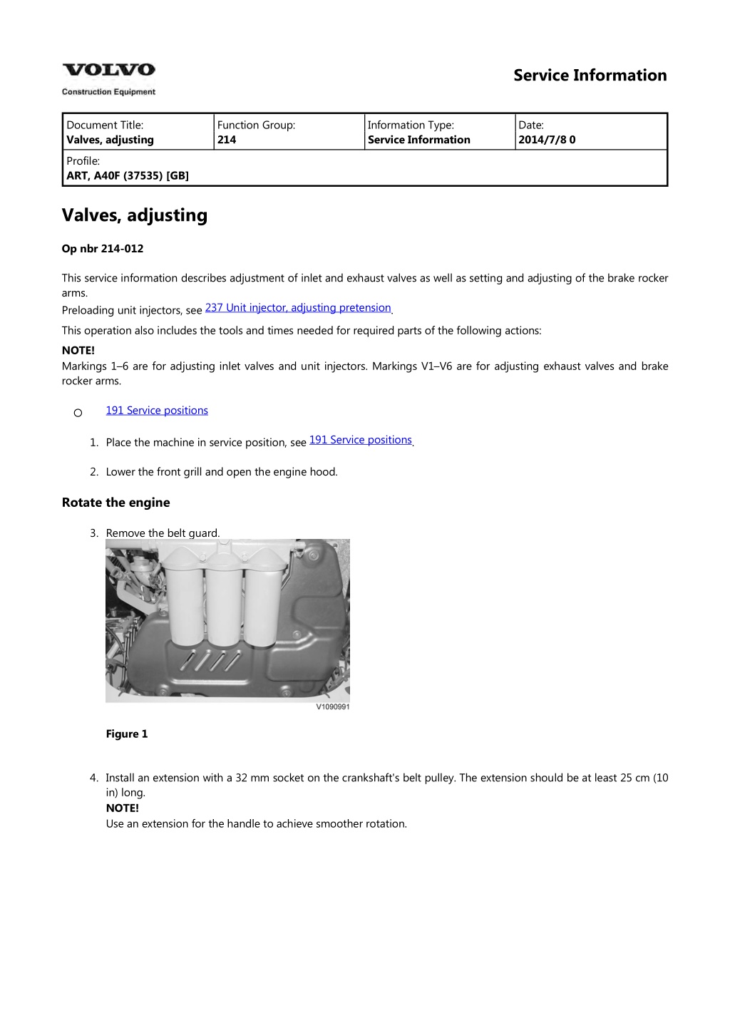
Service Information Document Title: Valves, adjusting Function Group: 214 Information Type: Service Information Date: 2014/7/8 0 Profile: ART, A40F (37535) [GB] Valves, adjusting Op nbr 214-012 This service information describes adjustment of inlet and exhaust valves as well as setting and adjusting of the brake rocker arms. Preloading unit injectors, see This operation also includes the tools and times needed for required parts of the following actions: NOTE! Markings 1 6 are for adjusting inlet valves and unit injectors. Markings V1 V6 are for adjusting exhaust valves and brake rocker arms. 237 Unit injector, adjusting pretension . 191 Service positions 191 Service positions 1. Place the machine in service position, see . 2. Lower the front grill and open the engine hood. Rotate the engine 3. Remove the belt guard. Figure 1 4. Install an extension with a 32 mm socket on the crankshaft's belt pulley. The extension should be at least 25 cm (10 in) long. NOTE! Use an extension for the handle to achieve smoother rotation.
Figure 2 5. Remove the valve cover. 6. Loosen the bolts for the brake rocker arms' leaf springs. Leave the leaf springs in place. Figure 3 7. Rotate the engine in its rotational direction (clockwise) until the nearest line marking on the camshaft stands between the marks on the bearing cap. NOTE! Markings 1 6 are for adjusting inlet valves and unit injectors. Markings V1 V6 are for adjusting exhaust valves and brake rocker arms.
Figure 4 Figure 5 Cylinder number Inlet valves, checking and adjusting 8. Check that the valve clearance between the yoke and rocker arm's thrust sleeve is according to . If needed, adjust as follows: Adjust correct valve clearance for the inlet valves. Place a tool in adjusting screw B as counterhold and tighten lock nut A with a box-end wrench. See Recheck the valve clearance. NOTE! Using a marking pen, mark when adjusting is done to keep track of which valves, unit injectors, and brake rocker arms have been adjusted. 214 Valve system, specification 214 Valve system, specification . Figure 6 NOTE! The unit injectors should only be adjusted if work has been done that involved removal of the rocker arm shaft. The unit injectors are adjusted using the same camshaft marking as the inlet valves. See . Valve yoke, balancing NOTE! When the adjusting screw is being screwed down, at the same time the yoke must be pressed down to contact with the valve stems. It is very important that the pressure is applied as close as possible to the middle of the yoke, see figure. Use a screwdriver or similar. 237 Unit injector, adjusting pretension Unit injectors, adjusting Exhaust valves, checking and adjusting
https://www.ebooklibonline.com Hello dear friend! Thank you very much for reading. Enter the link into your browser. The full manual is available for immediate download. https://www.ebooklibonline.com
9. Adjust to zero clearance on the valve yoke by loosening the lock nut (A) and adjusting screw (B) so that it does not have contact with the valve stem. Press on the valve yoke and then screw down the adjusting screw so that the yoke has contact with the valve stem. Then tighten the adjusting screw another hex edge (60 ). Then torque-tighten the lock nut (A) according to 214 Valve system, specification . Figure 7 10. Check that the valve clearance between the yoke and rocker arm's thrust sleeve is according to . Turn the sleeve so that it does not end up at an angle. Adjust the clearance and torque-tighten the lock bolt. Check the valve clearance and leave the feeler gauge in place. 214 Valve system, specification Figure 8 Brake rocker arm, checking 11. The feeler gauge still in place should maximally eliminate the exhaust valve clearance. Check the brake rocker arm's clearance between the rocker arm and the camshaft with a shim or feeler gauge. Check that the clearance is correct, see . NOTE! If the check-measurement deviates from the value in Specifications, adjust as follows, otherwise proceed to Error 214 Valve system, specification
check. Figure 9 NOTE! Leave the feeler gauge in place. Brake rocker arm, adjusting 12. Loosen the brake rocker arm's lock nut A and turn adjusting screw B 0.5 1 turn counter-clockwise. Place a shim or feeler gauge between the camshaft and the brake rocker arm's roller. The shim's thickness should be according to . Tighten adjusting screw B to contact and then half a turn so that the valve yoke is pressed downward and the exhaust valves open slightly. Then the engine brake mechanism is heavily loaded and all parts are in correct position. Loosen adjusting screw B until the shim or feeler gauge can be slid in and out with some effort. Lock adjusting screw B in this position with lock nut A, with torque, see 214 Valve system, specification 214 Valve system, specification . Figure 10 Error check 13. Remove the feeler gauge and shim. Check the clearance between the camshaft and the brake rocker arm's roller using a shim or feeler gauge with
214 Valve system, specification thickness according to It should be possible to slide the shim or feeler gauge into the clearance without resistance. NOTE! In case of insufficient clearance, start over from Exhaust valves, checking. . Figure 11 NOTE! The error check may never be used for adjusting work. 14. Adjust the rest of the valves, brake rocker arms, and unit injectors in the same way. 15. Check that the guide pin is located directly opposite the bowl in the spring plate. Tighten the bolts for the brake rocker arms' leaf springs. Figure 12 16. Install the valve cover. 17. Remove the rotation equipment and install the belt guard. 18. Close the engine hood and raise the front grill. 19. Restore the machine from service position. 20. Start the engine and check its function.
Service Information Document Title: Engine description Function Group: 215 Information Type: Service Information Date: 2014/7/8 0 timing gear, Profile: ART, A40F (37535) [GB] Engine timing gear, description Engine timing gear The engine has a rear-mounted timing gear on a 6 mm thick steel plate (1). The timing gear plate is fastened to the cylinder block with a number of M8-bolts (as well as an M10 bolt) and is sealed against the cylinder block and cylinder head with sealant. The sealant is applied in a bead on the plate. On the timing gear plate there is a drilled hole which, with the markings on the camshaft gear (A), are used together to enable correct installation of the camshaft gear. The crankshaft gear and the double transfer gear are marked together (B) for correct installation. Figure 1
V1083625 1. 2. 3. 4. 5. 6. 7. 8. 9. Timing gear plate Gear, crankshaft Transfer gear, double Not used Transfer gear, adjustable Camshaft gear Drive gear, air compressor Drive gear, fuel feed pump Transfer gear Drive gear, lubrication oil pump Vibration damper with teeth for inductive camshaft sensor 10. 11. A. B. Hole for guide pin Marking for crankshaft Belt transmission, description The belt transmission is located at the front end of the engine and has three multi-groove drive belts. The drive belt (3) drives the coolant pump (1), while the belt tensioner (7) keeps the belt tight. The drive belt (2) drives the alternator (and AC compressor if installed), while the belt tensioner (6) keeps the belt tight. Belt transmission for engine without diesel particle filter Figure 2 The figure shows engine D16F 1. 2. 3. 4. 5. Coolant pump Drive belt Drive belt AC Compressor Alternator
6. 7. Belt tensioner Belt tensioner The drive belt (3) drives the coolant pump (1), while the belt tensioner (8) keeps the belt tight. The drive belt (2) drives the alternator (and AC compressor if installed), while the belt tensioner (9) keeps the belt tight. The drive belt (7) drives the air pump (6), while the belt tensioner (10) keeps the belt tight. Belt transmission for engine with diesel particle filter Figure 3 The figure shows engine D16H 1. 2. 3. 4. 5. 6. 7. 8. 9. Coolant pump Drive belt Drive belt AC Compressor Alternator Air pump Drive belt Belt tensioner, coolant pump Belt tensioner, AC compressor and alternator Belt tensioner, air pump Drive gear, air pump 10. 11.
Service Information Document Title: Crank description Function Group: 216 Information Type: Service Information Date: 2014/7/8 0 mechanism, Profile: ART, A40F (37535) [GB] Crank mechanism, description Figure 1 A. B. C. Leading edge Middle centre bearing Trailing edge engine timing gear 1. 2. 3. 4. 5. 6. 7. 8. Bearing shells Thrust bearing Front teflon seal Rear teflon seal Gear Bolt, flywheel Bolt, crankshaft gear O-ring The crankshaft is drop-forged and has induction-hardened bearing surfaces. The crankshaft is carried in seven main bearings with replaceable bearing shells. In the middle main bearing there is also the thrust bearing which is made up of four washers
shaped like half-moons. At the leading edge the seal is made up of a teflon seal against the front crankshaft flange. At the trailing edge there is also a teflon seal that seals against a machined surface on crankshaft gear. The gear is fixed to the crankshaft with a guide pin and two bolts. In the rear crankshaft flange there is a groove for the O-ring that seals between the flange and the gear. Figure 2 1. 2. 3. 4. 5. 6. 7. 8. 9. Main bearing journal Lubrication channel, main bearing pin Lubrication channel, big-end bearing pin Damper housing Cast iron ring Bushes Flywheel Gear M16 bolts Guide pin Starter ring gear Groove for speed sensor 10. 11. 12. Lubrication of the crankshaft takes place via separate channels in the cylinder block to each main bearing. The main bearing pins have drilled lubrication channels and from each main bearing pin, except the middle one, there is a drilled channel to the nearest big-end bearing pin. The vibration damper is of hydraulic type and is bolted directly on the crankshaft's front flange. In the damper housing there is an oscillating mass in the form of a cast iron ring that can rotate freely on the bushings. The space between the damper housing and oscillating mass is filled with silicone oil of high viscosity. When the crankshaft rotates, torsional stresses are generated in the crankshaft by the pistons' power strokes. The viscous silicone oil evens out the movement between the
crankshaft's pulsating rotation and the oscillating mass' smooth rotation, thus reducing the vibrations. The flywheel and the gear located in-between are bolted on the crankshaft's rear flange with 14 M16-bolts. The flywheel is fitted to the crankshaft with a guide pin in the same position as the gear. On the outside there are machined grooves for the engine's speed sensor, speed sensor, flywheel, SE2701. The starter ring gear is shrink-fit on the flywheel and can be replaced. Supplementary information See also: 482 PTO (Power Take Off), description Diagnostics Detailed information about relevant warnings and the error codes below are found under the diagnostics section. Component SE2701 Control unit MID128 Message ID SID22
Service Information Document Title: Crankshaft, replacing front oil seal Function Group: 216 Information Type: Service Information Date: 2014/7/8 0 Profile: ART, A40F (37535) [GB] Crankshaft, replacing front oil seal Op nbr 216-014 88800021 Installation tool 9992000 Handle This operation also includes required tools and times for applicable parts of the following operations: 191 Service positions Removing 1. Place the machine in service position. See 191 Service positions 2. Lower the front grill and pump up the engine hood. 3. Remove the belt guard. Figure 1 The figure shows engine D16 4. For EGR-engine: Remove the belt for the air pump. Remove the middle belt for the coolant pump and the inner belt for the AC and alternator. Use a 1/2" ratchet handle to hold down the belt tensioner.
Figure 2 The figure shows an engine with EGR. 5. Belt pulley and vibration damper are balanced. Make a marking showing how they are located. Loosen and remove the rotation tool with the bolts for the for the crankshaft's belt pulleys and vibration damper. Remove the belt pulley/vibration damper. Figure 3 6. Clean the crankshaft end. Install 88800021 Installation tool. Drill, using the guide holes in the tool, two holes, =3.5 mm (0.14 in hole) in the seal. 7. Screw in two self-tapping screws 5 mm (0.20 in) in the seal. Figure 4 8. Screw in two fully threaded bolts M10x60 mm in the tool. Pull out the seal. Remove the screws and seal from the tool.
Figure 5 NOTE! Clean the seal position on the crankshaft and in the housing around the crankshaft. Check that contact surfaces and hub are free from damage. Installing 9. Check that the plastic ring, that works both as transport protection and installation tool, is in place in the seal ring. If the plastic ring is not in place, the seal ring may be damaged and must not be used. Fit the installation ring on the crankshaft journal and carefully transfer the seal from the installation ring to the crankshaft journal. Figure 6 1. 2. Installation ring Seal 10. Install 9992000 Handle in 88800021 Installation tool. Carefully tap in the seal until the tool bottoms out against the crankshaft. Remove the tool and check that the seal is installed correctly.
Figure 7 1. 2. 88800021 Installation tool 9992000 Handle 11. Install the belt pulley/vibration damper with the rotation tool and bolt down on the crankshaft. Tightening torque, see 216 Flywheel, tightening torques . Figure 8 1. Belt pulley/vibration damper 12. Install the inner and outer belt. Use a 1/2" ratchet handle to hold down the belt tensioners. 13. Fit the belt guard. 14. Close the engine hood and raise the front grill.
Service Information Document Title: Crankshaft, replacing rear oil seal Function Group: 216 Information Type: Service Information Date: 2014/7/8 0 Profile: ART, A40F (37535) [GB] Crankshaft, replacing rear oil seal Op nbr 216-018 9993590 Gear wheel 9998238 Drift 9992000 Handle 9990166 Installation tool This operation also includes required tools and times for applicable parts of the following operations: 421 Transmission, removing downward 421 Transmission, remove from a non mounted engine 421 Transmission, installing from underneath 421 Transmission, fitting on a non mounted engine NOTE! These methods are different alternatives to remove and install the transmission. A 421 Transmission, removing downward prerequisite for changing the crankshaft's 421 Transmission, remove from a non mounted engine oil seals is that the transmission is removed, see or . 1. Install 9993590 Gear wheel in the flywheel housing to prevent the crankshaft from rotating. 2. Loosen the bolts for the flywheel (14 pcs). 3. Remove the bolts, the thrust plate and the drive disc. Figure 1 4. Remove the flywheel.
Figure 2 5. Remove the seal ring together with bracket. Figure 3 6. Remove the crankshaft gear. Figure 4 7. Tap to undo the lock plates and loosen and remove the bolts (6 pcs.) for the bearing pin for the transfer gear.
Figure 5 8. Use two M10x30 m puller bolts to remove the bearing pin for the transfer gear. Figure 6 9. Remove the transfer gear with bearing races and the bearing pin. Catch any adjusting shims. Figure 7 10. NOTE! Place paper or similar in the bottom of the casing to collect drill burrs. Lube the drill bit with grease. Drill two holes with approx. 3 mm (0.12 in) in the old seal. Install two sheet metal screws and use a pry bar to pry loose the seal.
Suggest: If the above button click is invalid. Please download this document first, and then click the above link to download the complete manual. Thank you so much for reading
Figure 8 V1087687 11. Clean the crankshaft end. Check that the housing and crankshaft are free from damages. Install tool 9990166 Installation tool. Figure 9 12. Clean the seal position on the crankshaft and in the casing. Installing 13. Place the new seal ring on 9990166 Installation tool. Press in the seal with the tool's handle. 14. Remove the tool and check that the seal is installed correctly. NOTE! Check that the tool does not bottom against the guide pin in the crankshaft. Figure 10 15. Lube the bearings lightly with oil. Install the transfer gear with bearing races and the bearing pin as well as any
https://www.ebooklibonline.com Hello dear friend! Thank you very much for reading. Enter the link into your browser. The full manual is available for immediate download. https://www.ebooklibonline.com