Volvo A40E Articulated Dump Truck Service Repair Manual Instant Download
Please open the website below to get the complete manualnn// n

Download Presentation

Please find below an Image/Link to download the presentation.
The content on the website is provided AS IS for your information and personal use only. It may not be sold, licensed, or shared on other websites without obtaining consent from the author. Download presentation by click this link. If you encounter any issues during the download, it is possible that the publisher has removed the file from their server.
E N D
Presentation Transcript
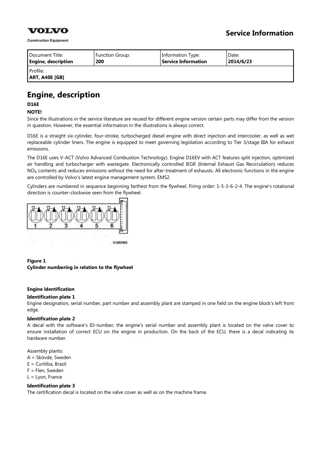
Service Information Document Title: Engine, description Function Group: 200 Information Type: Service Information Date: 2014/6/23 Profile: ART, A40E [GB] Engine, description D16E NOTE! Since the illustrations in the service literature are reused for different engine version certain parts may differ from the version in question. However, the essential information in the illustrations is always correct. D16E is a straight six-cylinder, four-stroke, turbocharged diesel engine with direct injection and intercooler, as well as wet replaceable cylinder liners. The engine is equipped to meet governing legislation according to Tier 3/stage IIIA for exhaust emissions. The D16E uses V-ACT (Volvo Advanced Combustion Technology). Engine D16EV with ACT features split injection, optimized air handling and turbocharger with wastegate. Electronically controlled IEGR (Internal Exhaust Gas Recirculation) reduces NO?contents and reduces emissions without the need for after-treatment of exhausts. All electronic functions in the engine are controlled by Volvo's latest engine management system, EMS2. Cylinders are numbered in sequence beginning farthest from the flywheel. Firing order: 1-5-3-6-2-4. The engine's rotational direction is counter-clockwise seen from the flywheel. Figure 1 Cylinder numbering in relation to the flywheel Engine identification Identification plate 1 Engine designation, serial number, part number and assembly plant are stamped in one field on the engine block's left front edge. Identification plate 2 A decal with the software's ID-number, the engine's serial number and assembly plant is located on the valve cover to ensure installation of correct ECU on the engine in production. On the back of the ECU, there is a decal indicating its hardware number. Assembly plants: A = Sk vde, Sweden E = Curitiba, Brazil F = Flen, Sweden L = Lyon, France Identification plate 3 The certification decal is located on the valve cover as well as on the machine frame.
Figure 2 Engine identification, D16E
Service Information Document Title: Engine Protection Function Group: 200 Information Type: Service Information Date: 2014/6/23 Profile: ART, A40E [GB] Engine Protection Engine protection, function description Introduction The engine control unit contains functionality that is to protect the engine from damage and minimize repair costs for damages that may occur in the engine's different systems. The parameters that activate the engine's protection system are: Low oil pressure Increased oil temperature Increased coolant temperature Low coolant level Increased crankcase pressure Increased charge-air temperature Increased boost pressure EGR-system Failure of flywheel's speed (rpm) sensor Water in fuel When the level of any of these parameters reaches the risk zone, different protective actions may be activated: Warnings Reduced torque (only in case of signal from sensors for EGR-system or in case of failure of the flywheel's speed (rpm) sensor) For examples of levels where engine protection is activated and which limitations are activated, see and Warnings There are several alarm levels for warnings. Yellow warning indicates a less serious malfunction or level, and red warning indicates that the engine must be turned off. For detailed description, see 387 Warning screens, general Reduced torque The engine protection function can limit the torque to reduce damage and repair costs in case the operator does not notice that a warning has been activated. Limited torque is activated in two cases: 3012 12F2604, brake cooling oil, circulation 3012 1F2003, limitation engine protection (EMS) Error Limitation EGR-system Failure of flywheel's speed (rpm) sensor 7 % 10 % The limitation is active until the parameter has returned to a safe level or until EMS is powered down. Degrees of engine protection By using different programs (software) it is possible to set different degrees of engine protection. Regardless of what degree of engine protection that has been selected, the operator always receives a warning when there is a malfunction. Oil pressure Since it takes a little while for the oil pressure to build up, there is a delay after the engine has been started until the pressure measurement takes place. The oil pressure is dependent on the engine speed, and thus there is no fixed limit for when the oil pressure warning is activated. Instead the pressure is compared to the current engine rpm. Coolant temperature The coolant's boiling point is dependent on the ambient air pressure, that is, at which altitude the machine is operated,
https://www.ebooklibonline.com Hello dear friend! Thank you very much for reading. Enter the link into your browser. The full manual is available for immediate download. https://www.ebooklibonline.com
which also decides at what temperature the warning is activated. Increased crankcase pressure The function measures and warns in case of increased crankcase pressure in a way that the pressure-increase value is obtained by comparing unfiltered and filtered crankcase pressure. The filter is designed so that a sudden pressure-increase gives a warning while a slowly increasing pressure, caused by normal wear, does not generate a warning. Water in fuel A sensor in the fuel system's pre-filter activates yellow warning when the water level becomes too high.
Service Information Document Title: Engine, identification Function Group: 200 Information Type: Service Information Date: 2014/6/23 Profile: ART, A40E [GB] Engine, identification Identification plate 1 Engine designation, serial number, part number and assembly plant are stamped in one field on the engine block's left front edge. Identification plate 2 A decal with the software's ID-number, the engine's serial number and assembly plant is located on the valve cover to ensure installation of correct ECU on the engine in production. On the back of the ECU, there is a decal indicating its hardware number. Assembly plants: A = Sk vde, Sweden E = Curitiba, Brazil F = Flen, Sweden L = Lyon, France Identification plate 3 The certification decal is located on the valve cover as well as on the left side of the machine's front frame. Figure 1 Engine identification, D16E
Figure 2 Certification decal
Service Information Document Title: E-ECU, MID 128, changing pre-programmed ECU Function Group: 200 Information Type: Service Information Date: 2014/6/23 Profile: ART, A40E [GB] E-ECU, MID 128, changing pre-programmed ECU Op nbr 200-070 This operation also includes required tools and times for applicable parts of the following operations: 200 E-ECU, MID 128, changing non-programmed ECU 1. Connect VCADS Pro computer and perform 17030-3 Parameter, programming. Use the function: Save all read parameters to job card. 200 E-ECU, MID 128, changing non-programmed ECU 2. Perform step 2 14. 3. Connect VCADS Pro computer and perform 17030-3 Parameter, programming. Program earlier read-out parameters according to the job card.
Service Information Document Title: E-ECU, MID 128, changing non-programmed ECU Function Group: 200 Information Type: Service Information Date: 2014/6/23 Profile: ART, A40E [GB] E-ECU, MID 128, changing non-programmed ECU Op nbr 200-068 1. Connect VCADS Pro computer and perform 28423-3 MID 128 ECU, programming When instructed to connect the new control unit, perform steps 2 15. Removing E ECU CAUTION Always follow instructions according to Electrical system, work instructions, electronic components 3001 Electrical system, special instructions for servicing, electronic components CAUTION Always follow instructions according to Electrical system, work instructions, electronic components 2. Figure 1 E-ECU 1. 2. 3. 4. 5. Connector EA Connector EB Screw for clamp Screw for cooler Screw for ECU Place the machine in service position. 3. Open the engine hood. NOTICE Turn off the electric power with the battery disconnect switch before starting any work. Also remove the
fuse for respective component. 4. Remove the three screws (3) that disconnect the clamps from the E-ECU. 5. Unplug the connectors EA and EB from the E-ECU. 6. Remove th screws (4) (6 pcs. ) that hold the cooler (3). 7. Remove the screws (5) (4 pcs.) that hold the E-ECU. 8. Carefully move aside the cooler and remove the E-ECU. NOTE! Work carefully so that hoses for the cooler are not damaged. Mounting E ECU 9. Lift in the E-ECU inside of the cooler. 10. Install the screws (5) (4 pcs.) that hold the E-ECU against the engine block. 11. Install the screws (4) (6 pcs.) that hold the cooler against the E-ECU. 12. Plug in the connectors EA and EB for the E-ECU. 13. Install the screws (3 pcs.) that hold the clamps against the E-ECU. 14. Close the engine hood. NOTE! When changing pre-programmed ECU, return to 200 E-ECU, MID 128, changing pre-programmed ECU step 3. 15. Finish VCADS Pro operation 28423-3 MID 128 ECU, programming.
Service Information Document Title: Cylinder compression, PC test Function Group: 210 Information Type: Service Information Date: 2014/6/23 Profile: ART, A40E [GB] Cylinder compression, PC test Connect the VCADS Pro computer and carry out 21006-3 Cylinder compression, test. (21006-3) This test indicates if there is any deviation in compression in any cylinder in relation to the other cylinders.
Service Information Document Title: Compression test Function Group: 210 Information Type: Service Information Date: 2014/6/23 Profile: ART, A40E [GB] Compression test Op nbr 210-002 9990006 Puller 9990185 Lifting tool 9990262 Adapter 9996400 Impact puller 9998599 Cleaning tool 9998248 Adapter 9998248 Adapter 9998248 Adapter 9998248 Adapter 9998248 Adapter 9998248 Adapter 88880003 Bracket 9988539 Pressure gauge 88820003 Setting tool 9993590 Gear wheel This operation also includes required tools and times for applicable parts of the following operations: 191 Service positions 214 Valves, adjusting 233 Fuel system, bleeding Removing 191 Service positions 1. Place the machine in service position, see . 2. Lower the front grill and pump up the engine hood. 3. Drain the fuel from the cylinder head by loosening the hose to the cylinder head. Install a drain nipple with hose.
Figure 1 4. Drain the cylinder head to avoid fuel in the engine oil. Open the connection by the feed line on the cylinder head and use an air nozzle to get out all of the fuel. Lead down the feed hose into a container. Since the feed pump will pump out fuel during the test, the container's volume must be at least 5 litres (1.3 US gal). Figure 2 5. Remove the valve cover. 6. If it is difficult to reach the valve cover's front, right bolt, proceed as follows for easier access: Loosen the bolts for the coolant pipes' front bracket and move the pipe assembly approx. 10 mm from the cylinder head. 7. The condition for reading off correct compression pressure is that the valve clearance is correct, see: 214 Valves, adjusting 8. Remove the IEGR-valve with the seal for the oil channel and save the spacer between the valve and cylinder head.
Figure 3 9. Remove the spring plates. Figure 4 10. Loosen the bolts for the rocker arm bridge equally in sequences, so that the rocker arm shaft is not bent. Remove the bolts and install the tools 9990185 and 88880003.
Figure 5 1. 9990185 11. Fixate the pistons in the exhaust rocker arms with rubber bands or similar so that the pistons do not fall out, and carefully lift away the rocker arm bridge. Rocker arm shaft's weight: : approx. 30 kg (66 lbs) Figure 6 12. Clean very thoroughly around the unit injector. Remove the electrical connection. Remove the bolt for the attaching yoke. Remove the injector together with the attaching yoke. Use 9996400 Impact puller, 9990262 Adapter and 9990006 Puller. Remove the other unit injectors in the same way. NOTE! Place each injector in separate new plastic bags. Mark which cylinder they were installed in. It is important to not mix up the injectors since they are classed for a certain cylinder.
Figure 7 1. 2. 3. 9996400, Impact hammer 9990262, Adapter 9990006, Puller 13. Clean the copper sleeve with the brush/brushes. Figure 8 1. 2. 3. Extension Brush Protective sleeve
14. Check that all adapters have O-rings and seal against the copper sleeve. Install adapters 9998248 in the unit injectors' place in the cylinder head. Figure 9 15. Tighten down the adapter with the unit injector's attaching yoke. Tightening torque: 40 Nm (30 lbf ft). NOTE! Keep in mind that the tightening torque here is only for holding the adapter during the test 16. Install the rocker arm bridge with the lifting tool 9990185. Tighten the bolts along the whole rocker arm shaft to prevent warping and to make sure that the guide pins fit in the camshaft's support bearing. See 214 Rocker arm shaft, tightening torques 17. Install the IEGR control valve. Check that the seal ring is placed correctly before the bolts for the IEGR control valve are tightened. 18. Install rubber bands between the adapters and the unit injectors' rocker arms. This is done so that the rocker arm will not rattle.
Figure 10 19. Install the oil pipe in place in the rocker arm shaft's oil channel. Install the IEGR-valve together with the spacer between the valve and the cylinder head. Check that the spacer and seals end up in the right place before the bolts are tightened. Figure 11 20. Connect compression gauge 9988539 to adapter 9998248 on the first cylinder. Run the engine with the starter motor until the needle on the compression gauge stops (max. compression value). Repeat the procedure for the other cylinders. On a new engine, the compression pressure is normally approx. 30 bar. Low compression pressure
on all cylinders indicates worn cylinder liners and/or worn piston rings. When comparing the compression pressure in the different cylinders and you detect any cylinder with lower pressure, this may be due to leaking valves, cracked piston rings, worn cylinder liner, or leaking cylinder head gasket. In case of this, Engine, overhauling should be done. Uniformity between the cylinders' compression pressure is the most important and should not exceed 20%. NOTE! The parking brake must be applied when cranking the engine with the starter motor. NOTE! Do not run the starter motor for longer than 10 seconds at a time, with intervals of 60 seconds. Assembling 21. Remove the compression gauge 9998539. 22. Remove the IEGR valve and the oil pipe. 23. Loosen the bolts for the rocker arm shaft evenly across the entire shaft, so that the rocker arm shaft is not subjected to transverse loading. Remove the bolts and install lifting tool 9990185 and 88880003. Carefully lift away the rocker arm shaft. Figure 12 24. Remove the adapters 9998248 25. Install the unit injectors with new O-rings and centre the unit injectors between the valve springs. Install the attaching yokes. Tightening torque: see 230 Tightening torque, fuel system NOTE! The tightening torques are different depending on if existing or new copper sleeve is used. 26. Lubricate the valve yoke and camshaft cams with engine oil.
27. Lift the rocker arm shaft into place with 9990185. Make sure that the guide pins fit in the support bearing for the camshaft. Tighten the attaching bolts, see 214 Rocker arm shaft, tightening torques . Figure 13 28. Lubricate a new seal with engine oil and install it in the IEGR-valve's oil channel. Figure 14 29. Lubricate the new seal rings with oil and install them on the oil pipe. Press in the end in the rocker arm shaft. Install the IEGR-valve together with the spacer between the valve and cylinder head. Check that the spacer and seals end up in the correct position before tightening the bolts.
Suggest: If the above button click is invalid. Please download this document first, and then click the above link to download the complete manual. Thank you so much for reading
Figure 15 214 Valves, adjusting 30. Adjust the clearance for the valves and the unit injectors, see . 31. Install the spring collets, see: 214 Valve mechanism, tightening torques Figure 16 32. Install the valve cover. Tighten the bolts according to the tightening diagram. Tightening torques, see 211 Tightening torques, valve cover . 33. Install the bracket for the expansion tank and install the expansion tank. 233 Fuel system, bleeding 34. Bleed air from the fuel system, see . 35. Pump down the engine hood and raise the front grill.
https://www.ebooklibonline.com Hello dear friend! Thank you very much for reading. Enter the link into your browser. The full manual is available for immediate download. https://www.ebooklibonline.com