Volvo A35F FS A35FFS Articulated Dump Truck Service Repair Manual Instant Download
Please open the website below to get the complete manualnn// n

Download Presentation

Please find below an Image/Link to download the presentation.
The content on the website is provided AS IS for your information and personal use only. It may not be sold, licensed, or shared on other websites without obtaining consent from the author. Download presentation by click this link. If you encounter any issues during the download, it is possible that the publisher has removed the file from their server.
E N D
Presentation Transcript
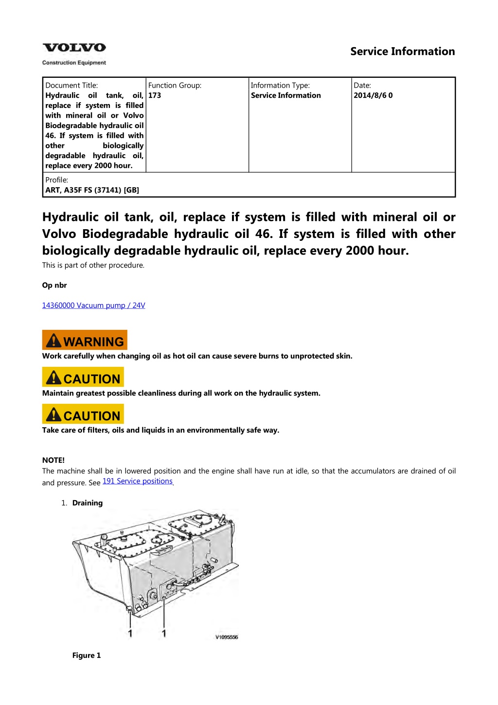
Service Information Document Title: Hydraulic oil tank, oil, replace if system is filled with mineral oil or Volvo Biodegradable hydraulic oil 46. If system is filled with other degradable hydraulic oil, replace every 2000 hour. Function Group: 173 Information Type: Service Information Date: 2014/8/6 0 biologically Profile: ART, A35F FS (37141) [GB] Hydraulic oil tank, oil, replace if system is filled with mineral oil or Volvo Biodegradable hydraulic oil 46. If system is filled with other biologically degradable hydraulic oil, replace every 2000 hour. This is part of other procedure. Op nbr 14360000 Vacuum pump / 24V WARNING Work carefully when changing oil as hot oil can cause severe burns to unprotected skin. CAUTION Maintain greatest possible cleanliness during all work on the hydraulic system. CAUTION Take care of filters, oils and liquids in an environmentally safe way. NOTE! The machine shall be in lowered position and the engine shall have run at idle, so that the accumulators are drained of oil and pressure. See . 191 Service positions 1. Draining Figure 1
1. Drain connections, hydraulic oil tank Remove the protective covers from the drain connections on the hydraulic oil tank's underside and at the rear end by the wheel. 2. Connect the drain hose to the drain connections. 3. Drain the oil into an oil barrel that holds approx. 262 litres (69.2 US gal). 4. After draining, remove the drain hose and reinstall the protective covers on the drain connections. 5. Filling. Figure 2 1. 2. 3. Filling Vacuum pump connection to breather filter hose Vacuum pump Remove the breather filter for the hydraulic oil tank. NOTE! To increase the fill rate, connect a vacuum pump. 6. Connect the vacuum pump to the breather filter hose, and plug in the cable in the 24 V socket in the right instrument panel in the cab. 7. Clean around the plug for the filler hole. NOTE! Always fill oil through the filler hole so that the oil is filtered. 8. Remove the plug for the filler hole in the cover. 160 Lubricants, specifications 900 Hydraulic system, capacities 9. Start the vacuum pump and fill oil, see return oil filter, volume see through the filler hole via the hydraulic oil's . Fill oil until the level glass shows max. level. 10. Reinstall the plug for the filler hole, to prevent oil from spraying out when the machine is started.
11. Turn off the vacuum pump and remove it from the breather filter hose. Unplug the cable from the instrument panel in the cab. 12. Reinstall the breather filter. NOTE! The engine may not be started when the vacuum pump is connected. 13. Start the machine and let it idle for approx. 5 minutes until the fans run at steady rpm. 14. Figure 3 1. Switch, FS-system Activate the hydraulic suspension with the switch. 15. Turn off the engine when the machine is in normal position. 16. Top up so that the oil reaches up to 3/4 in the level glass.
https://www.ebooklibonline.com Hello dear friend! Thank you very much for reading. Enter the link into your browser. The full manual is available for immediate download. https://www.ebooklibonline.com
Service Information Document Title: Hydraulic oil tank, return oil filter, replace, magnetic rods, clean Function Group: 173 Information Type: Service Information Date: 2014/8/6 0 and Profile: ART, A35F FS (37141) [GB] Hydraulic oil tank, return oil filter, replace, and magnetic rods, clean Op nbr This is part of other procedure. CAUTION Maintain greatest possible cleanliness during all work on the hydraulic system. CAUTION Take care of filters, oils and liquids in an environmentally safe way. 1. Clean around the cover for the hydraulic oil's return oil filter. 2. Spin off the cover. Figure 1 1. Return oil filter 3.
Figure 2 1. Filter insert for return oil filter Remove the filter inserts. 4. Figure 3 1. 2. 3. 4. Magnetic rod Filter Filter bracket Fastener nut Dismantle the filter insert as shown in the figure. 5. Figure 4 Magnetic rod Wipe clean the magnetic rod thoroughly and install a new filter in the filter holder. 6. Check O ring on the magnetic rod. 7. Reinstall the filter insert. 8. Repeat step 5 8 for the other filter insert. 9. Check O-ring for the cover and reinstall it.
Service Information Document Title: Hydraulic oil tank, breather filter, replacing Function Group: 173 Information Type: Service Information Date: 2014/8/6 0 Profile: ART, A35F FS (37141) [GB] Hydraulic oil tank, breather filter, replacing Op nbr This is part of other procedure. NOTE! The filter is of the disposable type, do not clean it, replace the filter. CAUTION Take care of filters, oils and liquids in an environmentally safe way. 1. Figure 1 1. Breather filter for hydraulic oil tank Change breather filter for the hydraulic oil tank.
Service Information Document Title: Brake cooling oil tank, breather filter, replacing Function Group: 173 Information Type: Service Information Date: 2014/8/6 0 Profile: ART, A35F FS (37141) [GB] Brake cooling oil tank, breather filter, replacing Op nbr This is part of other procedure. 1. Figure 1 1. Breather filter, brake cooling oil tank Change breather filter for the brake cooling oil tank.
Service Information Document Title: Fuel tank, axles, gearbox and dropbox, filter, replacing Function Group: 173 Information Type: Service Information Date: 2014/8/6 0 breather Profile: ART, A35F FS (37141) [GB] Fuel tank, axles, gearbox and dropbox, breather filter, replacing Op nbr This is part of other procedure. CAUTION Take care of filters, oils and liquids in an environmentally safe way. 1. Figure 1 1. Breather filter, fuel tank Change breather filter for the fuel tank.
2. Figure 2 1. Breather filter, front axle and dropbox Change breather filter for the dropbox and the tractor's front axle. 3. Figure 3 1. Breather filter, front bogie axle Change breather filter for the front bogie axle.
4. Figure 4 1. Breather filter, rear bogie axle Change breather filter for the rear bogie axle. 5. Figure 5 1. Breather filter for transmission Change breather filter for the transmission.
Service Information Document Title: Service brake, brake disc wear, check Function Group: 173 Information Type: Service Information Date: 2014/8/6 0 Profile: ART, A35F FS (37141) [GB] Service brake, brake disc wear, check Op nbr This is part of other procedure. NOTE! This applies for normal operating conditions, in tougher conditions the brake discs should be checked more often. 1. Apply the parking brake. 2. Start the engine and run up pressure in the system. 3. Apply the load and dump brake. Figure 1 1. Protective cap 4. Remove the wear indicator cap. Figure 2
1. Wear indicator 5. Figure 3 Insertion of indicator Carefully push in the wear indicator as far as possible, e.g., with a small screwdriver. Then measure the wear indicator's insertion inside of the nipple's face as shown. Note the measurement. 6. Figure 4 Cut-away view, wear indicator X is the insertion measurement The discs are worn out when measurement X equals 0 mm. Shaft Front axle Front bogie axle Rear bogie axle Value (mm) for new discs X=6.8 0.1 X=3.4 0.1 X=3.4 0.1 A35F / A35F FS A40F / A40F FS Front axle Front bogie axle Rear bogie axle X=6.8 0.1 X=4.5 0.1 X=4.5 0.1 7. Reinstall the wear indicator cap. 8. Repeat the measurement for the rest of the brakes. 9. Turn off the engine.
Service Information Document Title: Parking brake pads, check Function Group: 173 Information Type: Service Information Date: 2014/8/6 0 Profile: ART, A35F FS (37141) [GB] Parking brake pads, check Op nbr This is part of other procedure. 1. Figure 1 Check the pads' thickness as shown in figure. NOTE! Min. measurement for parking brake pads is 5 mm (0.2 in).
Service Information Document Title: Steering cylinder bearings, clearance, check Function Group: 173 Information Type: Service Information Date: 2014/8/6 0 Profile: ART, A35F FS (37141) [GB] Steering cylinder bearings, clearance, check Op nbr This is part of other procedure. NOTE! Checking is done by 2 persons. 1. Figure 1 1. 2. Cylinder rod Hitch Park the machine on level ground and apply the parking brake. 2. Secure the dial indicator with magnetic base on the hitch as shown in figure. 3. Start the machine and turn the steering wheel back and forth with small movements. Measure the movement of the piston rod bearing. NOTE! No clearance allowed.
4. Figure 2 1. 2. Cylinder end Frame Secure the dial indicator on the tractor's frame, and measure the movement of the cylinder barrel's bearing in a similar way as for the piston rod bearing. NOTE! No clearance allowed. 5. Perform the same measurements on the other steering cylinder.
Service Information Document Title: Load cushions, clearance, check Function Group: 173 Information Type: Service Information Date: 2014/8/6 0 body, rubber Profile: ART, A35F FS (37141) [GB] Load body, rubber cushions, clearance, check Op nbr This is part of other procedure. WARNING Never enter under an unsupported load body. 1. Clean around and under the rubber pads. 2. Check that the front rubber pads have equal clearance to the frame, 10 2 mm (0.39 0.08 in). Figure 1 1. Front rubber pad Figure 2 1. Rear rubber pad 3. Check that the rear rubber cushions, located over the bogie, have contact with the load body and are compressed equally on both sides.
Service Information Document Title: Steering first check of steering joint bearings after 6000 hours. Thereafter every hours. Function Group: 173 Information Type: Service Information Date: 2014/8/6 0 joint bearings, 2000 Profile: ART, A35F FS (37141) [GB] Steering joint bearings, first check of steering joint bearings after 6000 hours. Thereafter every 2000 hours. Op nbr This is part of other procedure. Checking clearance is carried out by 2 persons. NOTE! Make sure that the steering joint lock is mounted. 1. Figure 1 1. 2. Front frame Hitch Place a magnetic base with the dial indicator as shown in figure. The magnetic base is located against the hitch and the needle against the front frame. NOTE! To obtain a correct value, the dial indicator must be positioned on the middle of the hitch. 2. Start the engine and let it idle. NOTE! Check that no persons are in front of or behind the machine. 3. Apply the brake pedal and release the parking brake. 4. Move the gear selector to position "D". 5. Apply the parking brake.
6. Carefully release the brake pedal. 7. Reset the dial gauge. 8. Repeat from "Start the engine and let it idle", but move the gear selector to position "R" instead of position "D". 9. Read off the clearance on the dial indicator. NOTE! No clearance allowed! 10. Figure 2 1. 2. Hitch Front frame Move the magnetic base with dial indicator to the lower steering joint bearing as shown in figure. The magnetic base is located on the hitch and the needle against the front frame. 11. Repeat the method according to the above with the gear selector in both "D" and "R". NOTE! No clearance allowed!
Suggest: If the above button click is invalid. Please download this document first, and then click the above link to download the complete manual. Thank you so much for reading
Service Information Document Title: Frame clearance, check Function Group: 173 Information Type: Service Information Date: 2014/8/6 0 joint bearings, Profile: ART, A35F FS (37141) [GB] Frame joint bearings, clearance, check This is part of other procedure. Op nbr 11668008 Standard Jack Double 11668007 Standard Jack Single 1. Figure 1 1. 2. Trailer frame Hitch Place the dial indicator as shown. The magnetic base is located on the trailer frame and the needle against the hitch.
https://www.ebooklibonline.com Hello dear friend! Thank you very much for reading. Enter the link into your browser. The full manual is available for immediate download. https://www.ebooklibonline.com