Volvo A35D Articulated Dump Truck Service Repair Manual Instant Download
Please open the website below to get the complete manualnn// n

Download Presentation

Please find below an Image/Link to download the presentation.
The content on the website is provided AS IS for your information and personal use only. It may not be sold, licensed, or shared on other websites without obtaining consent from the author. Download presentation by click this link. If you encounter any issues during the download, it is possible that the publisher has removed the file from their server.
E N D
Presentation Transcript
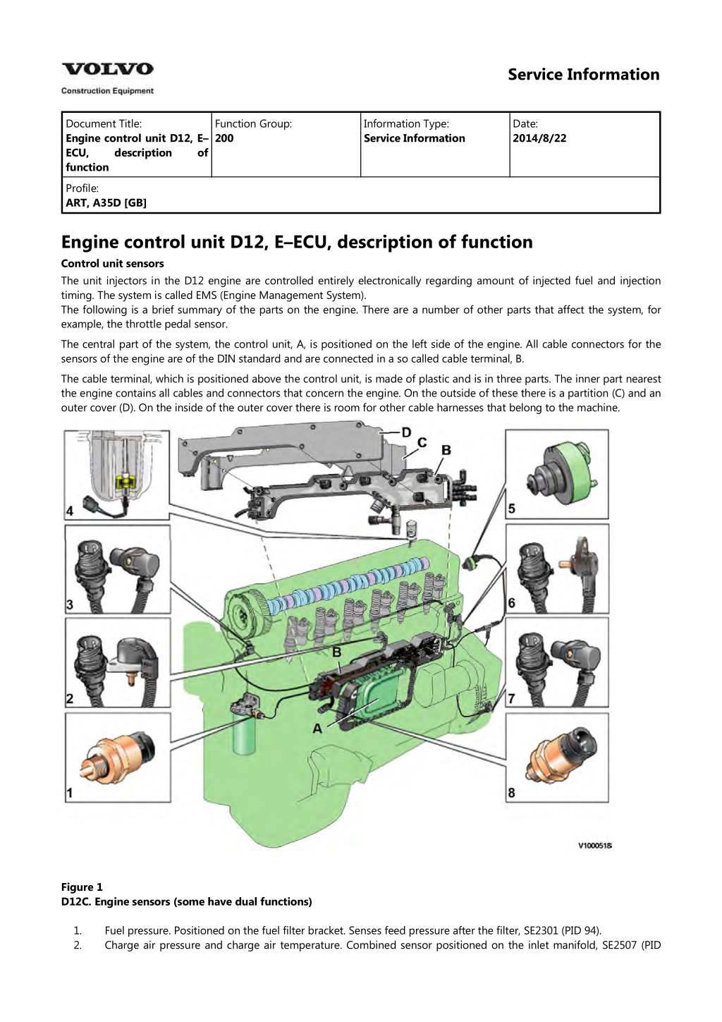
Service Information Document Title: Engine control unit D12, E ECU, description function Function Group: 200 Information Type: Service Information Date: 2014/8/22 of Profile: ART, A35D [GB] Engine control unit D12, E ECU, description of function Control unit sensors The unit injectors in the D12 engine are controlled entirely electronically regarding amount of injected fuel and injection timing. The system is called EMS (Engine Management System). The following is a brief summary of the parts on the engine. There are a number of other parts that affect the system, for example, the throttle pedal sensor. The central part of the system, the control unit, A, is positioned on the left side of the engine. All cable connectors for the sensors of the engine are of the DIN standard and are connected in a so called cable terminal, B. The cable terminal, which is positioned above the control unit, is made of plastic and is in three parts. The inner part nearest the engine contains all cables and connectors that concern the engine. On the outside of these there is a partition (C) and an outer cover (D). On the inside of the outer cover there is room for other cable harnesses that belong to the machine. Figure 1 D12C. Engine sensors (some have dual functions) 1. 2. Fuel pressure. Positioned on the fuel filter bracket. Senses feed pressure after the filter, SE2301 (PID 94). Charge air pressure and charge air temperature. Combined sensor positioned on the inlet manifold, SE2507 (PID
105), SE2508 (PID 102). Camshaft position. Positioned near the top of the cylinder head at the front, SE2703 (SID 21). Coolant level. Positioned in the expansion tank, SE2603 (PID 111). Air pressure and air temperature. Combined sensor, positioned on the connecting pipe between the air filter and the turbocharger, SE2501 (PID 172), SE2502 (PID 107). Coolant temperature. Positioned in the rear end of the cylinder head, SE2606 (PID 110). Flywheel position and rotational speed. Positioned in the flywheel housing, SE2701 (SID 22). Oil pressure and oil temperature. Combined sensor positioned in the lubrication system main duct in the cylinder block, SE2202 (PID 175), SE2203 (PID 100). 3. 4. 5. 6. 7. 8. Figure 2 D12D Engine sensors (some have dual functions) 1. 2. 3. 4. 5. 6. 7. 8. 9. Sensor for coolant level, SE2603 Sensor for coolant temperature, SE2606 Sensor for charge air pressure/temperature, SE2507/SE2508 Tachometer sensor, flywheel, SE2701 Sensor for oil level/temperature, SE2205/SE2202 Sensor for crankcase pressure, SE2509 Sensor for oil pressure, SE2203 Camshaft sensor, engine position, SE2703 Sensor for air pressure/temperature, SE2501/SE2502 Sensor for feed pressure, fuel, SE2301 Sensor for water indicator, SE2302 10. 11.
Service Information Document Title: E ECU D12, Functions Function Group: 200 Information Type: Service Information Date: 2014/8/22 Profile: ART, A35D [GB] E ECU D12, Functions Fuel amounts, unit injectors Figure 1 Unit injector "Bosch" Figure 2 Unit injector "Delphi" Exhaust brake Applies only to machine equipped with engine D12C
https://www.ebooklibonline.com Hello dear friend! Thank you very much for reading. Enter the link into your browser. The full manual is available for immediate download. https://www.ebooklibonline.com
Figure 3 Exhaust brake Exhaust brake Applies only to machine equipped with engine D12D Figure 4 Exhaust brake Compression brake Applies only to machine equipped with engine D12C Figure 5 MA2503 (PPID 122), solenoid valve for compression brake Temperatures, pressures and rpms
Figure 6 SE2507 (PID !05)/SE2508 (PID 102) Charge air temperature/pressure Preheating element, preheating Figure 7 Preheating element Raised engine speed. The switch is connected to the cab control unit (C ECU) which sends a message via the data bus to the engine control unit (E ECU). NOTE! Raised engine speed is optional equipment. Figure 8 Switch, raised engine speed
Service Information Document Title: E ECU D12D, Input and Output terminals Function Group: 200 Information Type: Service Information Date: 2014/8/22 Profile: ART, A35D [GB] E ECU D12D, Input and Output terminals INPUTS ECU OUTPUTS Digital Digital Control, MA2301 2306 Detection (RE2501, pin 87) of preheating injectors 1 6, Monitor, air filter, pressure, SE2502 Control, pressure governor, exhaust brake PWM2501 (EPG1), Monitor, coolant level, SE2603 Control, pressure governor / shutter, exhaust brake (EPG2), MA2502 Preheating induction RE2501 air, Control, exhaust circulation, MA2504 [T1] [T1]Only applies to A35D equipped with engine D12DAAE3 and A40D equipped with engine D12DABE3 INPUTS ECU Analogue Sensor, engine oil temperature, SE2202 Sensor, engine oil pressure, SE2203 Sensor, fuel pressure, SE2301 Sensor, ambient air, temperature, SE2501 Sensor, charge-air temperature, SE2507 Sensor, charge-air pressure, SE2508 Sensor, coolant temperature, engine, SE2606 Sensor, engine speed, SE2701 Sensor, camshaft speed, SE2703 Monitor, water in fuel, SE2302
Monitor, engine oil level, SE2205 Sensor, crankcase pressure, SE2509
Service Information Document Title: Engine D12, description Function Group: 200 Information Type: Service Information Date: 2014/8/22 Profile: ART, A35D [GB] Engine D12, description Engine D12, description Engine D12 is available in two versions, D12C and D12D. See the product plate for the machine regarding which engine version applies to the machine. Engine D12 is an straight, six-cylinder, direct injection, diesel engine with at cylinder capacity of 12 litres. It is equipped with a turbocharger and an intercooler and electronically controlled fuel injection, EMS (Engine Management System). It has an overhead camshaft and unit injectors instead of injection pump and injectors. The unit injectors are positioned in the centre above the pistons and are controlled via the camshaft and a control unit (E- ECU). The control unit is positioned on the left side of the cylinder block. Engine D12C Applies to machine equipped with engine D12C, with serial number according to the table. Machine Place of manufacture, serial number BRA 12999 11999 ASH 61303 60286 PED 71999 A35D A40D Engine D12D Applies to machine equipped with engine D12D, with serial number according to the table. Machine Place of manufacture, serial number BRA 13001 12001 PED 72001 70001 A35D A40D Figure 1
Service Information Document Title: Engine, identification Function Group: 200 Information Type: Service Information Date: 2014/8/22 Profile: ART, A35D [GB] Engine, identification Identification plate 1 Engine designation, serial number, part number and assembly plant are stamped in one field on the engine block's left rear edge Identification plate 2 A decal with the software's ID-number, the engine's serial number and assembly plant is located on the valve cover to ensure installation of correct ECU on the engine in production. On the back of the ECU, there is a decal indicating its hardware number. Assembly plants: A = Sk vde, Sweden E = Curitiba, Brazil F = Flen, Sweden L = Lyon, France Identification plate 3 The certification decal is located on the valve cover as well as on the left side of the machine's front frame. Figure 1 Engine identification, D12D
Figure 2 Certification decal
Service Information Document Title: Compression test Function Group: 210 Information Type: Service Information Date: 2014/8/22 Profile: ART, A35D [GB] Compression test Op nbr 210-002 9990185 Lifting tool 9998248 Adapter 88880003 Bracket 9998248 Adapter 9998248 Adapter 9998248 Adapter 9998248 Adapter 9998248 Adapter 9998665 Adapter 9988539 Pressure gauge 9990006 Puller 9990262 Adapter 9996400 Impact puller 9998599 Cleaning tool 88820003 Setting tool 9993590 Gear wheel This operation also includes the tools and times needed for required parts of the following actions: 214 Valves, adjusting 233 Fuel system, bleeding Dismantling 1. Place the machine in service position. 2. Pump up the engine hood. 3. Drain the cylinder head to avoid fuel in the engine oil. Loosen and plug the hose connection in the engine's trailing edge. Loosen the feed hose and lead it into a container. Since the feed pump will pump out fuel during the test, the container's volume must be at least5 litres (1.3 US gal). Figure 1
V1022266 4. Open the bleeder nipple on the cylinder head's leading edge and use an air nozzle in the fuel's inlet channel to lead out the fuel. NOTE! Collect the excess fuel in a container. 5. Remove the hose from the oil trap and remove the valve cover. NOTE! Do not use a nut runner since the studs bolts may come loose from the cylinder head and damage electrical cables and valve cover. Figure 2 V1022264 6. Remove the unit injectors' electrical connections. 7. Remove the IEGR control valve's electrical connections and wipe clean around the control valve. 8. Remove the valve cover's stud bolt located in front of the IEGR control valve. Figure 3 Stud bolt 9. Remove the bolts for the IEGR control valve. Remove the control valve and the pipe between the valve and the
rocker arm shaft. Figure 4 V1050815 10. Loosen the bolts for the rocker arm bridge equally in sequences, so that the rocker arm shaft is not bent. Remove the bolts and carefully lift away the rocker arm bridge with 9990185 and 88880003. NOTE! For engines with VEB: fixate the pistons in the rocker arms with rubber bands or similar so that the pistons do not fall out. NOTE! Pistons and rocker arms are classed as units. Marking (one, two, or three dots) must match.
Figure 5 11. NOTE! Clean very thoroughly around the unit injectors. Remove the bolts for the unit injectors' attaching yoke. Remove the unit injector with 9996400 Impact puller9990262 Adapter9990006 Puller. NOTE! Place each injector in separate new plastic bags. Mark which cylinder they were installed in. It is important to not mix up the injectors since they are classed for a certain cylinder.
Figure 6 12. Clean the unit injectors' copper sleeves with a brush on an extension. Figure 7 1. 2. 3. Extension Brush Protective sleeve 13. Check that all adapters have O-rings and seal against the copper sleeve. Install adapters 9998248 in the unit injectors' place in the cylinder head.
Figure 8 14. Tighten down the adapter with the unit injector's attaching yoke. Tightening torque: 40 Nm (30 lbf ft). Figure 9 V1022271 15. Install the rocker arm bridge with the lifting tool 9990185. Tighten the bolts along the whole rocker arm shaft to prevent warping and to make sure that the guide pins fit in the camshaft's support bearing. See . 214 Rocker arm shaft, tightening torques 16. Install the IEGR control valve. Check that the seal ring is placed correctly before the bolts for the IEGR control valve are tightened. 17. Transfer the rubber bands so that they are located between the adapter and the unit injector's rocker arm. This is done so that the rocker arm will not rattle.
Figure 10 V1022272 18. The condition for reading off correct compression pressure is that the valve clearance is correct. See: 214 Valves, adjusting 19. Connect compression gauge 9988539 to adapter 9998248 on the first cylinder. Run the engine with the starter motor until the needle on the compression gauge stops (max.compression value). Repeat the procedure for the other cylinders. On a new engine, the compression pressure is normally approx. 30 bar. Low compression pressure on all cylinders indicates worn cylinder liners and/or worn piston rings. When comparing the compression pressure in the different cylinders and you detect any cylinder with lower pressure, this may be due to leaking valves, cracked piston rings, worn cylinder liner, or leaking cylinder head gasket. In case of this, Engine, overhauling should be done. Uniformity between the cylinders' compression pressure is the most important and should not exceed 20%. NOTE! The parking brake must be applied when cranking the engine with the starter motor. NOTE! Do not run the starter motor for longer than 10 seconds at a time, with intervals of 60 seconds. Figure 11 V1022273 Assembling 20. Remove the compression gauge 9998539 and adapters 9998248. 21. Loosen the bolts for the rocker arm shaft evenly across the entire shaft, so that the rocker arm shaft is not subjected to transverse loading. Remove the bolts and install lifting tool 9990185 and 88880003. Carefully lift away the rocker arm shaft.
Figure 12 V1039942 22. Install the unit injectors with new O-rings and centre the unit injectors between the valve springs. Install the attaching yokes. Tightening torque: see 230 Tightening torque, fuel system Figure 13 23. Lift the rocker arm shaft into place with 9990185. Make sure that the guide pins fit in the support bearing for the
Suggest: If the above button click is invalid. Please download this document first, and then click the above link to download the complete manual. Thank you so much for reading
camshaft. Tighten the attaching bolts, see: 214 Rocker arm shaft, tightening torques 24. Wipe clean the cylinder head by the IEGR-valve. Check for any impurities or dirt in the cylinder head's oil channel. 25. Install the IEGR control valve with new O-rings. 26. Install the stud bolt in front of the IEGR-valve. 27. Install the electrical connections for the unit injectors and the control valve. 214 Valves, adjusting 28. Adjust the valves and the unit injectors, see . 29. Install the valve cover. Tighten the bolts according to tightening diagram. Tightening torque, see 200 Engine, tightening torques 30. Install the fuel lines' connections on the cylinder head. 31. Bleed the fuel system, see 233 Fuel system, bleeding
https://www.ebooklibonline.com Hello dear friend! Thank you very much for reading. Enter the link into your browser. The full manual is available for immediate download. https://www.ebooklibonline.com

, SE2508 (PID 102).")