Volvo A30F Articulated Dump Truck Service Repair Manual Instant Download
Please open the website below to get the complete manualnn// n

Download Presentation

Please find below an Image/Link to download the presentation.
The content on the website is provided AS IS for your information and personal use only. It may not be sold, licensed, or shared on other websites without obtaining consent from the author. Download presentation by click this link. If you encounter any issues during the download, it is possible that the publisher has removed the file from their server.
E N D
Presentation Transcript
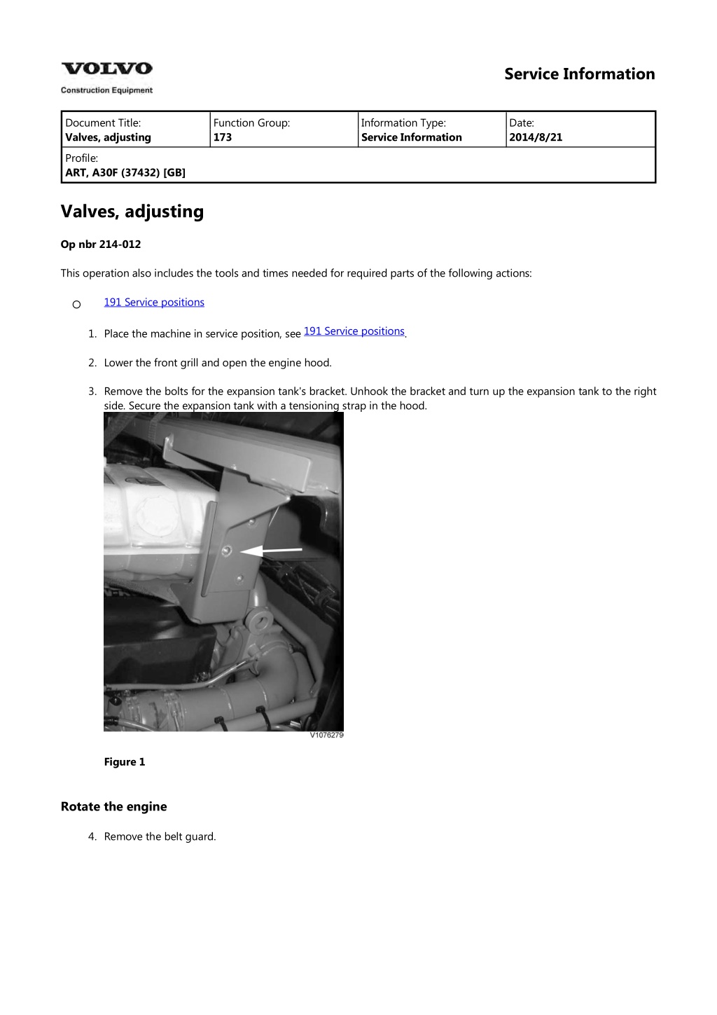
Service Information Document Title: Valves, adjusting Function Group: 173 Information Type: Service Information Date: 2014/8/21 Profile: ART, A30F (37432) [GB] Valves, adjusting Op nbr 214-012 This operation also includes the tools and times needed for required parts of the following actions: 191 Service positions 191 Service positions 1. Place the machine in service position, see . 2. Lower the front grill and open the engine hood. 3. Remove the bolts for the expansion tank's bracket. Unhook the bracket and turn up the expansion tank to the right side. Secure the expansion tank with a tensioning strap in the hood. Figure 1 Rotate the engine 4. Remove the belt guard.
Figure 2 1. Belt cover 5. Install an extension with a 32 mm socket on the crankshaft's belt pulley. The extension should be at least 25 cm (10 in) long. NOTE! Use an extension for the handle to achieve smoother rotation. Figure 3 6. Remove the valve cover. 7. Rotate the engine in the rotational direction until the closest line marking on the camshaft stands between the marks on the bearing cap. (The camshaft is rotated counter-clockwise seen from the front). NOTE! Markings 1 6 are for adjusting inlet valves and unit injectors. Markings V1 V6 are for adjusting exhaust valves.
Figure 4 Camshaft marking Figure 5 Cylinder number Inlet valves, checking and adjusting 8. Check that the valve clearance between the yoke and rocker arm's thrust sleeve is according to . If needed, adjust as follows: Adjust correct valve clearance for the inlet valves. Place a tool in adjusting screw B as counterhold and tighten lock nut A with a box-end wrench. See Recheck the valve clearance. NOTE! Using a marking pen, mark each rocker arm when adjusting is done to keep track of which valves have been adjusted. 214 Valve system, specification 214 Valve system, specification .
https://www.ebooklibonline.com Hello dear friend! Thank you very much for reading. Enter the link into your browser. The full manual is available for immediate download. https://www.ebooklibonline.com
Figure 6 NOTE! The unit injectors should only be adjusted if work has been done that involved removal of the rocker arm shaft. The unit injectors are adjusted using the same camshaft marking as the inlet valves. See . 237 Unit injector, adjusting pretension Unit injectors, adjusting Exhaust valves, checking 9. Rotate the engine to the next marking V1 V6. Try to press down the rocker arm against the valve yoke. If it springs back there is still pressure in the piston. 10. Pull the rocker arm piston's spring outwards, at the same time as the rocker arm is pressed down to contact against the yoke. The oil film that may remain inside of the piston is punctured when the piston is lifted from its seat and the setting becomes more exact. Use a heavy gauge wire or hooked tool to pull out the spring. Figure 7
Figure 8 11. Check that the valve clearance between the yoke and rocker arm's thrust sleeve is according to . Turn the sleeve so that it does not end up at an angle. 214 Valve system, specification Figure 9 Exhaust valves, adjusting 12. If the valve clearance needs to be adjusted, remove the lock bolt and the shim. Using the measured value, calculate the thickness of the new shim. Install the shim and tighten the lock bolt with torque according to . Use shim, see parts catalogue. Check the valve clearance. NOTE! Fixate the valve yoke when the lock bolt is loosened or tightened to avoid bending of the valve stems. 214 Valve system, specification Figure 10 13. Adjust the rest of the valves in the same way. 14. Install the valve cover. 15. Reinstall the expansion tank. 16. Remove the rotation equipment and install the belt guard.
Figure 11 17. Close the engine hood and raise the front grill. 18. Restore the machine from service position. 19. Start the engine and check its function.
Service Information Document Title: Suspension cylinder (GHS), rubber bearings, check Function Group: 173 Information Type: Service Information Date: 2014/8/21 Profile: ART, A30F (37432) [GB] Suspension cylinder (GHS), rubber bearings, check Op nbr This is part of other procedure. 1. Figure 1 1. Rubber bushing Visually check both cylinders' rubber bushings for wear or heavy crack formation. NOTE! Not checking the rubber bearings may result in damage to cylinders and shorten the machine's operating life.
Service Information Document Title: Suspension cylinder (GHS), function check Function Group: 173 Information Type: Service Information Date: 2014/8/21 Profile: ART, A30F (37432) [GB] Suspension cylinder (GHS), function check Op nbr 725-013 NOTE! The machine must meet the following criteria to obtain correct values: 1. 2. 3. 4. 5. 6. Diesel tank filled Hydraulic oil tank filled to max. level Level ground Free from dirt Body without load Rock the machine by making a few small steering wheel movements to ensure that both cylinders have the same load. 1. Place the machine in service position, see section 191 Service positions 2. Loosen the protective caps on the cylinders. Figure 1 1. 2. Protective cap Bleed plug 3. Measure as shown in figure and see measurement table. Measure the cylinders on both sides.
Figure 2 A. B. Edge on pipe Centre of nipple Temp (C) -30 -20 -10 0 10 20 30 40 50 60 (F) -22 -4 14 32 50 68 86 104 122 140 Height (mm) 5.5 mm ( 0.22 in) 268 272 275 279 282 286 289 293 296 300
Service Information Document Title: Suspension cylinder (GHS), oil changing Function Group: 173 Information Type: Service Information Date: 2014/8/21 Profile: ART, A30F (37432) [GB] Suspension cylinder (GHS), oil changing Op nbr 725-010 11666135 Gas filling kit 11666051 Pressure gauge 14290266 Hose 14290266 Hose 88830034 Adapter 11668007 Standard Jack Single 936439 Nipple WARNING Risk of injury when the machine sinks down when the cylinders are drained from oil. This operation also includes required tools and times for applicable parts of the following operations: 191 Service positions NOTE! The machine must meet the following criteria to obtain correct values: 1. 2. 3. 4. 5. Diesel tank filled Hydraulic oil tank filled to max. level Level ground Free from dirt Body without load NOTE! The underbody skid plates should be installed and fastened in place for this operation. 191 Service positions 1. Place the machine in service position, see . WARNING Risk of injury when the machine sinks down when the cylinders are drained from oil. Oil draining 2. Loosen the protective caps on the cylinders.
Figure 1 1. 2. Protective caps Bleed plug 3. Connect a drain hose (length 1100 mm (43 in) thread M7) to the lower valve on the cylinder. Collect the oil in a suitable container. 4. Open by loosening the lock nut on the valve. Figure 2 WARNING Make sure it is at least 10 cm of space between you and the machine and that there are no objects that might get crushed when the machine is lowered. 5. Drain the oil until the cylinder is pressureless. 6. Connect the drain hose to the upper gas nipple to drain the oil pipe of oil. 7. Repeat the method on the other cylinder. NOTE! Handle the oil in an environment-friendly manner.
Filling oil 8. Fill with new oil in the upper connection by inserting a drain hose a (300 mm (12 in) with max. 10 mm (0.39 in) ) in the cylinder. Oil volume, see 720 Suspension cylinder (GHS), specifications 1. 2. 3. 4. 5. Fill with oil until it starts to run out from the breather plug. Wait awhile until the oil has stopped running. Close the breather plug. Top up with 150 ml (5.1 oz). Install the gas nipple for the upper connection. Figure 3 9. Repeat the method on the other side. 10. Connecting the gas filling equipment as shown in figure. Figure 4
1. 2. 3. 4. 5. 6. 11666135 Gas filling kit 11666051 Pressure gauge 14290266 Hose 936439 Testing nipple 14290266 Hose 88830034 Adapter 11. Connect 88830034 Adapter from the gas cylinder to the gas nipple on the upper connection. Open the gas nipple and fill gas. Measure elevation (mm/in) of the machine until the machine has reached correct height, see 725 Suspension cylinder (GHS), function check Figure 5 1. 88830034 Adapter 12. Repeat the method on the other cylinder.
Service Information Document Title: Diesel check and clean Function Group: 173 Information Type: Service Information Date: 2014/8/21 particulate filter, Profile: ART, A30F (37432) [GB] Diesel particulate filter, check and clean Op nbr 254-001 WARNING Risk of burns - stop the diesel engine and allow it to cool down before starting any work. This operation also includes the tools and times needed for required parts of the following actions: 191 Service positions 191 Service positions 1. Place the machine in service position, see . 2. Secure the exhaust pipe and the outlet end with two boards over the spill guard. Tighten together with a C-clamp. In the outlet end there is a sensor for temperature and differential pressure that is easy to damage unless the outlet end is secured adequately, see 254 Exhaust Aftertreatment System, description . Figure 1 3. Loosen the safety chain for the hydraulic hoses. Move the hose assembly aside. Figure 2 4. Install an M8 lifting eye in the hole on top of the heat shield. Secure the filter in an overhead crane with a shackle
and a lifting sling. Loosen the steel strap that holds the filter to the bracket. Also loosen the tensioning strap for the burner part and slide in a spacer between the burner part and the bracket to relieve it. Figure 3 5. Remove the clamps for the filter connections. If the filter is to be reinstalled, mark its position. Carefully loosen the filter. NOTE! Make sure that the flanges on the filter are not damaged. 6. Lift away the filter. Weight: approx. 35 kg (77 lbs) Figure 4 NOTE! Handle the filter carefully to prevent any impact damage. 7. Check if soot particles have accumulated in the burner part. Clean or vacuum out the soot. Figure 5
8. Unpack the spare part filter from the box. 9. The removed filter must be placed in the protective bag that is supplied with the new filter. Follow Volvo Core handling instructions. NOTE! Handle the filter carefully to prevent any impact damage. 10. Transfer the heat shield plates to the new particle filter. Figure 6 11. Clean the grooves in the particle filter and outlet end from remaining soot and the old gaskets. One gasket is placed in the groove on the outlet end, the other in the particle filter. Use new gaskets. NOTE! Graphite gaskets are fragile. Figure 7 12. Wipe off the contact surface on the clamps with a rag and cleaning fluid. Place new clamps over the burner and outlet end. Install the clamps carefully so that they maintain their round shape. 13. Secure the filter in an overhead crane in the same way as before. Lift the filter into place. Install new clamps loosely at both ends. Max. 5 Nm (3.7 lf ft). Install the steel straps.
Figure 8 254 Exhaust aftertreatment system, tightening torques 14. Torque-tighten the clamps and steel straps, see the clamp closest to the burner part. Check that the outlet end has not been displaced so that the exhaust pipe is leaning, then tighten the clamp. Tap on the clamps, start farthest from the bolt and tap both ways all the way around. Remove the lifting devices. . First tighten 15. Restore the machine from service position. 16. Run VCADS operation: 25456 3 (Reset ash load). 17. Start the engine and check that there are no leaks. Repeat tightening when needed.
Service Information Document Title: Ignition cables, change Function Group: 173 Information Type: Service Information Date: 2014/8/21 Profile: ART, A30F (37432) [GB] Ignition cables, change Op nbr This is part of other procedure. DANGER Risk of electrocution. Contact with live parts will cause death or serious injury. Never touch live electrical parts. WARNING Risk of burns! Hot machine parts could cause burns. Allow hot machine parts to cool before performing adjustments or service. Wear personal protective equipment. NOTE! Do not remove the ignition cables until the machine has cooled down. Risk of damage to the ignition cables. 1. Turn off the electric power with the battery disconnector. 2. Loosen and swing out the protective cover for the particulate filter. Figure 1 1. Protective cover 3. Disconnect and remove the ignition cables together with the ground cables.
Suggest: If the above button click is invalid. Please download this document first, and then click the above link to download the complete manual. Thank you so much for reading
Figure 2 1. Position of brackets for ignition cables Figure 3 1. Ignition cables' ground cables 4. Install the new ignition cables and the ground cables. 5. Clamp the ignition cables and ground cables so that they cannot come into contact with the particulate filter's burner. 6. Reinstall the protective cover. 7. Turn on the electric power with the battery disconnector.
https://www.ebooklibonline.com Hello dear friend! Thank you very much for reading. Enter the link into your browser. The full manual is available for immediate download. https://www.ebooklibonline.com