Volvo A30E Articulated Dump Truck Service Repair Manual Instant Download
Please open the website below to get the complete manualnn// n

Download Presentation

Please find below an Image/Link to download the presentation.
The content on the website is provided AS IS for your information and personal use only. It may not be sold, licensed, or shared on other websites without obtaining consent from the author. Download presentation by click this link. If you encounter any issues during the download, it is possible that the publisher has removed the file from their server.
E N D
Presentation Transcript
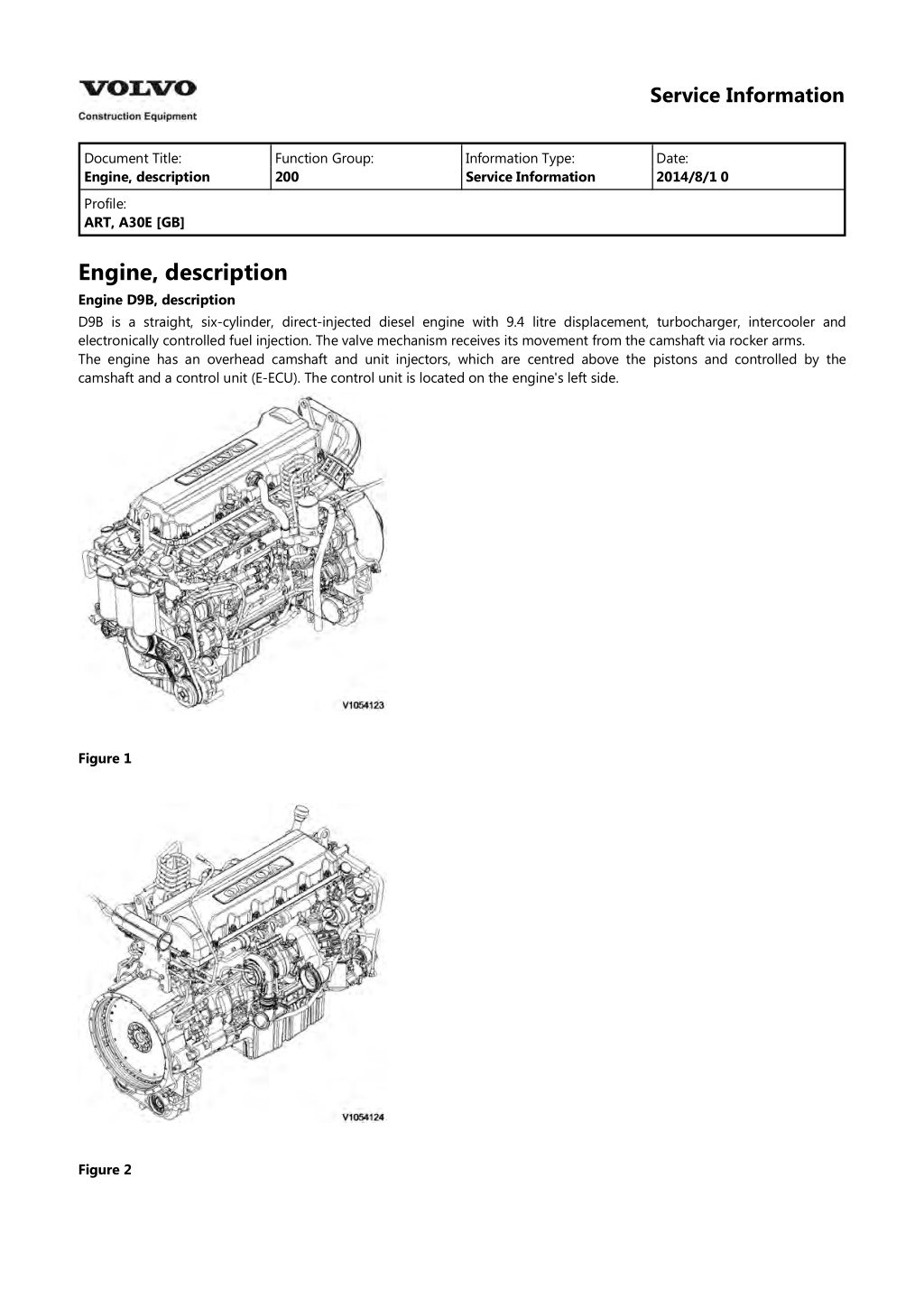
Service Information Document Title: Engine, description Function Group: 200 Information Type: Service Information Date: 2014/8/1 0 Profile: ART, A30E [GB] Engine, description Engine D9B, description D9B is a straight, six-cylinder, direct-injected diesel engine with 9.4 litre displacement, turbocharger, intercooler and electronically controlled fuel injection. The valve mechanism receives its movement from the camshaft via rocker arms. The engine has an overhead camshaft and unit injectors, which are centred above the pistons and controlled by the camshaft and a control unit (E-ECU). The control unit is located on the engine's left side. Figure 1 Figure 2
Service Information Document Title: Engine, sensor positions Function Group: 200 Information Type: Service Information Date: 2014/8/1 0 Profile: ART, A30E [GB] Engine, sensor positions Control unit sensors The following is a brief summary of the parts on the engine. There are a number of other parts that affect the system, for example, the throttle pedal sensor. The central part of the system, the control unit is positioned on the left side of the engine. All cable connectors for the engine's sensors are of DIN standard and are connected in a so-called cable box. Figure 1 Engine D9, sensors (some have double functions) 1. 2. 3. 4. Sensor for coolant level, SE2603 Sensor for coolant temperature, cooling circuit converter, SE2601 Sensor for charge air pressure/temperature, SE2507/SE2508 Tachometer sensor, flywheel, SE2701
5. 6. 7. 8. 9. Sensor for oil level/temperature, SE2205/SE2202 Sensor for crankcase pressure, SE2509 Sensor for oil pressure, SE2203 Camshaft sensor, engine position, SE2703 Sensor for air pressure/temperature, SE2501/SE2502 Sensor for feed pressure, fuel, SE2301 Sensor for water indicator, SE2302 Sensor for coolant temperature, cooling circuit engine/retarder, SE2602 10. 11. 12.
https://www.ebooklibonline.com Hello dear friend! Thank you very much for reading. Enter the link into your browser. The full manual is available for immediate download. https://www.ebooklibonline.com
Service Information Document Title: Engine, identification Function Group: 200 Information Type: Service Information Date: 2014/8/1 0 Profile: ART, A30E [GB] Engine, identification Identification plate 1 Engine designation, serial number, part number and assembly plant are stamped in one field on the engine block's left front edge. Identification plate 2 A decal with the software's ID-number, the engine's serial number and assembly plant is located on the valve cover to ensure installation of correct ECU on the engine in production. On the back of the ECU, there is a decal indicating its hardware number. The E-ECU is located on the engine's left side. Assembly plants: A = Sk vde, Sweden E = Curitiba, Brazil F = Flen, Sweden L = Lyon, France Figure 1 Identification plate 3 The certification decal is located on the valve cover as well as on the left side, at the back of the machine's front frame inside of the steps.
Service Information Document Title: E-ECU, MID 128, changing pre-programmed ECU Function Group: 200 Information Type: Service Information Date: 2014/8/1 0 Profile: ART, A30E [GB] E-ECU, MID 128, changing pre-programmed ECU Op nbr 200-070 This operation also includes required tools and times for applicable parts of the following operations: 200 E-ECU, MID 128, changing non-programmed ECU 1. Connect VCADS Pro computer and perform 17030-3 Parameter, programming. Use the function: Save all read parameters to job card. 200 E-ECU, MID 128, changing non-programmed ECU 2. Perform step 2 14. 3. Connect VCADS Pro computer and perform 17030-3 Parameter, programming. Program earlier read-out parameters according to the job card.
Service Information Document Title: E-ECU, MID 128, changing non-programmed ECU Function Group: 200 Information Type: Service Information Date: 2014/8/1 0 Profile: ART, A30E [GB] E-ECU, MID 128, changing non-programmed ECU Op nbr 200-068 1. Connect VCADS Pro computer and perform 28423-3 MID 128 ECU, programming When instructed to connect the new control unit, perform steps 2 15. Removing E ECU CAUTION Always follow instructions according to Electrical system, work instructions, electronic components 3001 Electrical system, special instructions for servicing, electronic components CAUTION Always follow instructions according to Electrical system, work instructions, electronic components 2. Figure 1 E-ECU 1. 2. 3. 4. 5. Connector EA Connector EB Screw for clamp Screw for cooler Screw for ECU Place the machine in service position. 3. Open the engine hood. NOTICE Turn off the electric power with the battery disconnect switch before starting any work. Also remove the
fuse for respective component. 4. Remove the three screws (3) that disconnect the clamps from the E-ECU. 5. Unplug the connectors EA and EB from the E-ECU. 6. Remove th screws (4) (6 pcs. ) that hold the cooler (3). 7. Remove the screws (5) (4 pcs.) that hold the E-ECU. 8. Carefully move aside the cooler and remove the E-ECU. NOTE! Work carefully so that hoses for the cooler are not damaged. Mounting E ECU 9. Lift in the E-ECU inside of the cooler. 10. Install the screws (5) (4 pcs.) that hold the E-ECU against the engine block. 11. Install the screws (4) (6 pcs.) that hold the cooler against the E-ECU. 12. Plug in the connectors EA and EB for the E-ECU. 13. Install the screws (3 pcs.) that hold the clamps against the E-ECU. 14. Close the engine hood. NOTE! When changing pre-programmed ECU, return to 200 E-ECU, MID 128, changing pre-programmed ECU step 3. 15. Finish VCADS Pro operation 28423-3 MID 128 ECU, programming.
Service Information Document Title: Cylinder compression, PC test Function Group: 210 Information Type: Service Information Date: 2014/8/1 0 Profile: ART, A30E [GB] Cylinder compression, PC test Connect the VCADS Pro computer and carry out 21006-3 Cylinder compression, test. (21006-3) This test indicates if there is any deviation in compression in any cylinder in relation to the other cylinders.
Service Information Document Title: Compression test Function Group: 210 Information Type: Service Information Date: 2014/8/1 0 Profile: ART, A30E [GB] Compression test Op nbr 210-002 9990006 Puller 9990185 Lifting tool 9996400 Impact puller 9998599 Cleaning tool 9998248 Adapter 9998248 Adapter 9998248 Adapter 9998248 Adapter 9998248 Adapter 9998248 Adapter 9993590 Gear wheel 88880003 Bracket 9988539 Pressure gauge 88820016 Setting tool This operation also includes the tools and times needed for required parts of the following actions: 191 Service positions 237 Unit injector, adjusting pretension 233 Fuel system, bleeding 214 Valves, adjusting Removing 191 Service positions 1. Place the machine in service position, see . 2. Lower the front grill and pump up the engine hood. 3. Drain the cylinder head to avoid fuel in the engine oil. Open the connection by the return line on the cylinder head and install a hose. Figure 1
4. Loosen the feed hose from the connection by the ECU. Use an air nozzle to get out all of the fuel. Lead the feed hose into a container Since the feed pump will pump out fuel during the test, the container's volume must be at least 5 litres (1.3 US gal). Figure 2 5. Secure the expansion tank with a strap, and then loosen the bracket for the expansion tank. Figure 3 6. Remove the engine's front lifting eye. This is done to enable installation of the lifting tool on the rocker arm bridge. 7. Remove the hose from the oil trap and remove the valve cover. 8. The condition for reading off correct compression pressure is that the valve clearance is correct. See: 214 Valves, adjusting 9. Remove the IEGR control valve's electrical connections and wipe clean around the control valve. Remove the valve.
Figure 4 10. Loosen the bolts for the rocker arm shaft, evenly distributed across the rocker arm shaft to avoid shear stresses. Remove the bolts. Lift away the rocker arm shaft with tool 9990185 and 88880003. Rocker arm shaft's weight: : approx. 30 kg (66 lbs) Figure 5 9990185 11. Clean very thoroughly around the unit injector. Remove the electrical connection. Remove the bolt for the attaching yoke. Remove the injector together with the attaching yoke. Use 9996400 Impact puller, 9990262 Adapter, and 9990006 Puller. Remove the other unit injectors in the same way. NOTE! Place each injector in separate new plastic bags. Mark which cylinder they were installed in. It is important to not mix up the injectors since they are classed for a certain cylinder.
Figure 6 1. 2. 3. 9996400, Impact hammer 9990262, Adapter 9990006, Puller 12. Clean the copper sleeve with the brush/brushes included in kit 9998599. Figure 7 1. 2. 3. Extension Brush Protective sleeve
13. Check that all adapters have O-rings and seal against the copper sleeve. Install adapters 9998248 in the unit injectors' place in the cylinder head. Figure 8 14. Tighten down the adapter with the unit injector's attaching yoke. Tightening torque: 40 Nm (30 lbf ft). NOTE! Keep in mind that the tightening torque here is only for holding the adapter during the test Figure 9 15. Install the rocker arm bridge with the lifting tool 9990185. Tighten the bolts along the whole rocker arm shaft to prevent warping and to make sure that the guide pins fit in the camshaft's support bearing. See . 214 Rocker arm shaft, tightening torques 16. Install the rubber bands so that they are located between the adapter and the unit injector's rocker arm. This is done so that the rocker arm will not rattle.
Figure 10 17. Install the IEGR control valve. Check that the seal ring is placed correctly before the bolts for the IEGR control valve are tightened. NOTE! The parking brake must be applied when cranking the engine with the starter motor. 18. Connect compression gauge 9988539 to adapter 9998248 on the first cylinder. Run the engine with the starter motor until the needle on the compression gauge stops (max. compression value). Repeat the procedure for the other cylinders. On a new engine, the compression pressure is normally approx. 30 bar. Low compression pressure on all cylinders indicates worn cylinder liners and/or worn piston rings. When comparing the compression pressure in the different cylinders and you detect any cylinder with lower pressure, this may be due to leaking valves, cracked piston rings, worn cylinder liner, or leaking cylinder head gasket. In case of this, Engine, overhauling should be done. Uniformity between the cylinders' compression pressure is the most important and should not exceed 20%. Figure 11 NOTE! Do not run the starter motor for longer than 10 seconds at a time, with intervals of 60 seconds. Assembling 19. Loosen the bolts for the rocker arm shaft evenly across the entire shaft, so that the rocker arm shaft is not subjected to transverse loading. Remove the bolts and install lifting tool 9990185 and 88880003. Carefully lift away the rocker arm shaft. 20. Remove the compression gauge 9998539 and adapters 9998248. 21. Install the unit injectors in the places where they were installed from the beginning with new O-rings and centre the unit injectors between the valve springs. Install 230 Tightening torque, fuel system the attaching yokes. Tightening torque: see
Figure 12 22. Lift the rocker arm shaft into place with 9990185. Make sure that the guide pins fit in the support bearing for the camshaft. Tighten the attaching bolts, see 214 Rocker arm shaft, tightening torques . Figure 13 23. Install the control valve (IEGR-valve). Figure 14 24. Install the electrical connections for the unit injectors and the control valve. 237 Unit injector, adjusting pretension 25. Adjust clearance of the valves and unit injectors, see .
26. Install the valve cover. Tighten the bolts according to the tightening diagram. Tightening torques, see 211 Tightening torques, valve cover 27. Install the fuel lines' connections on the cylinder head. 28. Install the bracket for the expansion tank and install the expansion tank. 29. Install the engine's front lifting eye. 233 Fuel system, bleeding 30. Bleed the fuel system, see . 31. Pump down the engine hood and raise the front grill.
Service Information Document Title: Engine and transmission, removing Function Group: 210 Information Type: Service Information Date: 2014/8/1 0 Profile: ART, A30E [GB] Engine and transmission, removing Op nbr 210-073 88830051 Lifting tool This operation also includes required tools and times for applicable parts of the following operations: 191 Service positions 173 Coolant, changing 1. Place the machine in service position, see 191 Service positions 2. Lower the front grill and pump up the engine hood. Figure 1 Front grill 3. Turn off the electric power with the battery disconnect switch. 4. Remove the front and rear underbody skid plates. Figure 2 Underbody skid plates
1. 2. 3. 4. 5. Front underbody skid plate Rear underbody skid plate, left Rear underbody skid plate, right Front cross member Rear cross member 5. Remove the front and rear cross members. Weight: approx.15 kg (33 lbs). 6. Drain the hydraulic oil tank. Volume, see 030 Capacities The drain nipple is located on the middle of the tank by the suction line for the front hydraulic pumps. NOTE! The oil drain hose is inserted in the pipe for the ladder on the inside of the front grill. Figure 3 Draining hydraulic oil tank WARNING Risk of burns. The fluid may be hot. 7. Drain the engine oil. Volume, see 030 Capacities Figure 4 Draining engine oil 8. Drain the gearbox oil. Volume, see Capacities
Suggest: If the above button click is invalid. Please download this document first, and then click the above link to download the complete manual. Thank you so much for reading
Figure 5 Draining transmission oil 9. Remove the cap for the expansion tank. Figure 6 10. Drain the coolant, see: 173 Coolant, changing 11. When the expansion tank is empty, open the air bleeder nipples on the cooling pipes. Figure 7 1. Air bleeder nipples 12. Disconnect the drain hose from the oil sump. Plug and fold it aside.
https://www.ebooklibonline.com Hello dear friend! Thank you very much for reading. Enter the link into your browser. The full manual is available for immediate download. https://www.ebooklibonline.com