Volvo A30C Articulated Dump Truck Service Repair Manual Instant Download
Please open the website below to get the complete manualnn// n

Download Presentation

Please find below an Image/Link to download the presentation.
The content on the website is provided AS IS for your information and personal use only. It may not be sold, licensed, or shared on other websites without obtaining consent from the author. Download presentation by click this link. If you encounter any issues during the download, it is possible that the publisher has removed the file from their server.
E N D
Presentation Transcript
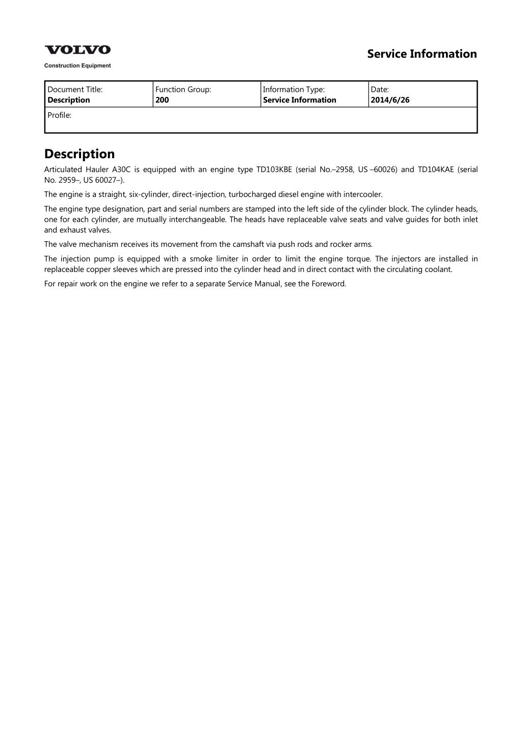
Service Information Document Title: Description Function Group: 200 Information Type: Service Information Date: 2014/6/26 Profile: Description Articulated Hauler A30C is equipped with an engine type TD103KBE (serial No. 2958, US 60026) and TD104KAE (serial No. 2959 , US 60027 ). The engine is a straight, six-cylinder, direct-injection, turbocharged diesel engine with intercooler. The engine type designation, part and serial numbers are stamped into the left side of the cylinder block. The cylinder heads, one for each cylinder, are mutually interchangeable. The heads have replaceable valve seats and valve guides for both inlet and exhaust valves. The valve mechanism receives its movement from the camshaft via push rods and rocker arms. The injection pump is equipped with a smoke limiter in order to limit the engine torque. The injectors are installed in replaceable copper sleeves which are pressed into the cylinder head and in direct contact with the circulating coolant. For repair work on the engine we refer to a separate Service Manual, see the Foreword.
Service Information Document Title: Diagnosis Display Unit Function Group: 200 Information Type: Service Information Date: 2014/6/26 using Service Profile: Diagnosis using Service Display Unit Error codes The table below shows a summary of error codes which may appear on the display unit and the most likely cause of the fault/error. The following trouble-shooting diagram shows, in addition to error codes, also error symptoms, probable error cause and the action required to rectify the fault as well as a reference to the service display unit. Error messages Display Cause Control malfunction transmission lamp, Central warning in 201 Engine pressure ER 202 Engine pressure low Electrical fault sensor circuit (SE16) Too low lubricating oil pressure, engine yes Trouble-shooting diagram Error code Symptom Probable error cause Action Service screen (figure) No. display unit 201 Engine pressure, sensor fault (SE16) Faulty sensor SE16 or faulty cable harness to the same. Measure cable harness and check sensor. resistance in oil Figure 5.12 Number 23 Normal oil pressure; 0 Low oil pressure; 1 202 Low oil (SE16) Lubricating oil pressure too low. engine pressure Figure 5.12 Number 23 Normal oil pressure; 0 Low oil pressure; 1
https://www.ebooklibonline.com Hello dear friend! Thank you very much for reading. Enter the link into your browser. The full manual is available for immediate download. https://www.ebooklibonline.com
Service Information Document Title: Tightening torques Function Group: 200 Information Type: Service Information Date: 2014/6/26 Profile: Tightening torques Engine Engine Flywheel housing Front engine mounting, see [Invalid linktarget] Item 1 Item 2 Item 3 Rear engine mounting, see [Invalid linktarget] Item 1 Item 2 Item 3 Item 4 140 N m, 14 kgf m (103 lbf ft) 220 N m, 22 kgf m (162 lbf ft) 140 N m, 14 kgf m (103 lbf ft) 50 N m, 5 kgf m (37 lbf ft) 85 N m, 8.5 kgf m (63 lbf ft) 134 N m, 13.4 kgf m (100 lbf ft) 220 N m, 22 kgf m (162 lbf ft) 220 N m, 22 kgf m (162 lbf ft) Figure 1
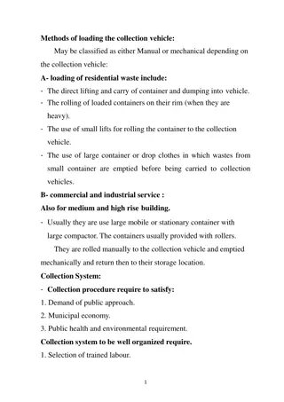
Service Information Document Title: Trouble-shooting Function Group: 200 Information Type: Service Information Date: 2014/6/26 Profile: Trouble-shooting Methods and aids When a fault is suspected or found, it is important immediately to determine the cause of the fault and identify the faulty component. Certain faults are indicated by the red central warning lamp on the instrument panel lighting up at the same time as the buzzer is sounding or in that the LED (Light Emitting Diode) on the ECU is flashing. In case of a warning, the engine should be stopped immediately and a service engineer should be called. In order to facilitate and make the trouble-shooting more efficient, there are a number of aids available. Contronic Display Unit Contronic Service Display Unit 999 3721 Multimeter 11 666 140 Multi-pin breaker box 11 668 002 With the aid of the Service Display Unit it is possible to determine sensor faults, engine oil pressure and low engine oil pressure. In case of a fault/error the Service Display Unit will show an error code (ER indication) and a reading (value) deviating from the normal. Error codes, possible causes of malfunction and suitable action are described under Diagnosis using Service Display Unit . When an error code or a deviating value is shown, measuring resistance is used to establish whether the fault is in a component e.g. sensor) or if the cable harness to the same is faulty.
Service Information Document Title: Compression test, warm engine Function Group: 210 Information Type: Service Information Date: 2014/6/26 Profile: Compression test, warm engine Op nbr 21002 999 6643 Puller 999 8009 Adapter 998 8539 Compression gauge Prerequisite condition: The valves are correctly adjusted, see [Invalid linktarget] . 1. Place the machine on level ground and apply the parking brake. 2. Carefully clean around the injectors and at the connections for the fuel delivery pipes and the leak-off fuel pipes. WARNING The fuel delivery pipes are pressure prestressed and must under no circumstances be bent or reshaped. If a pressure prestressed fuel delivery pipe is bent or deformed, there is a great risk that the pipe will break. A damaged delivery pipe must always be replaced with a new pipe! Removing 3. Remove the fuel delivery pipes. CAUTION Place protective caps on all injectors and on the injection pump connections. 4. Remove the leak-off fuel pipe. Figure 1 1. 999 6643 Extractor 5. Remove the injector for the number 1 cylinder. When necessary use extractor 999 6643 for taking out the injector.
See [Invalid linktarget] . Make sure that the copper washer which is positioned between the injector and the copper sleeve comes out together with the injector, [Invalid linktarget] . If it does not come out, use a hook made from a piece of wire to get it out. Figure 2 1. Copper washer 6. Install the adapter 999 8009 and secure it using the injector retaining yoke and nut. See [Invalid linktarget] . Tightening torque: 50 N m (5.0 kgf m) (37 lbf ft). Figure 3 1. 2. 999 8009, Adapter 999 8539, Compression gauge 7. Connect compression gauge 998 8539. See [Invalid linktarget] . 8. Pull out the stop button and secure the injection pump stop lever in the stop position. This is to prevent fuel from running out of the delivery valves when the engine is cranked with the starter motor. 9. Check that the gear selector is in neutral. 10. Crank the engine with the starter motor for 5 seconds. 11. Remove the testing equipment and re-install the injector together with a new copper washer. Tightening torque: 50 N m (5.0 kgf m) (37 lbf ft). 12. Carry out a compression test of cylinders 2, 3, 4, 5 and 6 in the same way as for cylinder number 1. Remove the pipe between the turbocharger and intercooler when testing cylinder number 6.
Normal compression pressure is 2.6 MPa (26 bar) (377 psi) at 220 rpm. CAUTION Differences of 10 % in the compression pressure between the cylinders is fully acceptable and does not constitute a reason for further action as for example valve reconditioning. Installing 13. Install the leak-off fuel pipe together with new copper washers. 14. Re-install the pipe between the turbocharger and the intercooler. WARNING The fuel delivery pipes are pressure prestressed and must under no circumstances be bent or reshaped. If a pressure prestressed fuel delivery pipe is bent or deformed, there is a great risk that the pipe will break. A damaged delivery pipe must always be replaced! 15. Install the fuel delivery pipes. Observe the greatest possible cleanliness and make sure that the pipes are not bent or deformed. Tighten the pipe nuts. Tightening torque: 15 25 N m (1.5 2.5 kgf m) (18 lbf ft). 16. Restore the stop function. Start the engine and check that there are no leaks.
Service Information Document Title: Engine and transmission, installing Function Group: 210 Information Type: Service Information Date: 2014/6/26 Profile: Engine and transmission, installing Op nbr 21074 999 2754 Lifting tool 999 2755 Lifting tool 999 2756 Lifting tool 999 6052 Lifting tool Torque wrench 0 400 N m (0 40 kgf m) (0 295 lbf ft) 1. Connect the lifting device to the engine. Incline the engine and transmission to the correct angle. 2. Lower the unit and install the engine mountings (the front ones first). Tightening torque, front: 220 N m (22 kgf m) (162 lbf ft). Tightening torque, rear: 140 N m (14 kgf m) (103 lbf ft). 3. Install the propeller shaft. Tightening torque: 180 N m (18 kgf m) (133 lbf ft). 4. Install the components on the transmission: two new oil filters connector EH oil filler pipe and oil dipstick hose for breather filter connector for retarder valve and connector for sensor S13. 5. Connect the hoses to the extra oil cooler for the transmission. 6. Connect the hose to the power take-off lubricating oil pump. 7. Connect the suction lines to pumps 1, 2 and 4. 8. Connect the return oil hoses for the hydraulic pumps. 9. Connect the hoses (B, C, D, E and F) to the collecting pipe. See [Invalid linktarget] Figure 1 Collecting pipe for leak-off oil A. Return oil line from fan motor (9/16 UNF)
B. C. D. E. F. Leak-off oil line from thermostat valve (9/16 UNF) Leak-off oil line from pump 1 (steering and tipping system) (7/8 UNF) Leak-off oil line from pump 4 (steering and tipping system) (7/8 UNF) Leak-off oil line from pump 2 (steering and tipping system) (7/8 UNF) Leak-off oil line from pump 3 (fan drive) (7/8 UNF) 10. Install governor control arm and stop control cables. Connect the hoses to the brake pump. Install alternator, exhaust pipe and oil filters. Install the air cleaner. 11. Connect coolant hoses, oil coolers, the fuel lines to injection pump. 12. Install engine hood and the left side plate. 13. Clamp hoses and electrical leads where clamping has been removed. 14. Open the hydraulic oil tank shut-off valve. 15. Fill with coolant, see [Invalid linktarget] . Fill hydraulic oil. See the Operator"s Manual, Hydraulic oil, changing . Fill engine oil. See the Operator"s Manual, Engine, changing oil . Check that there is a sufficient amount of oil in the transmission, before starting the engine. 16. Bleed the fuel system, see [Invalid linktarget] . 17. Swing in the radiator and tighten down. 18. Switch on the current with the battery disconnect switch, see [Invalid linktarget] . Figure 2 A. B. On Off 1. 2. 3. 4. 5. Front guard plate Front, transverse member Rear guard plate, left Rear guard plate, right Rear, transverse member 19. Start the engine and test the function. Check that there are no leaks. Run until warm and check the coolant level and the transmission oil level. 20. Install the front (2) and the rear (5) transverse members. Install guard plates (1), (3) and (4), see [Invalid linktarget] .
Service Information Document Title: Engine and transmission, removing Function Group: 210 Information Type: Service Information Date: 2014/6/26 Profile: Engine and transmission, removing Op nbr 21073 999 2754 Lifting tool 999 2755 Lifting tool 999 2756 Lifting tool 999 6052 Lifting tool Torque wrench 0 400 N m (0 40 kgf m) (0 295 lbf ft) WARNING There is a danger of scalding when removing the expansion tank cap (radiator cap), as the cooling system is pressurised when hot. Hot oil may cause burns. CAUTION Plug all pipes, hoses and connections after disconnection. Removing 1. Place the machine in the service position. Figure 1 A. On
B. Off 1. 2. 3. 4. 5. Front guard plate Front, transverse member Rear guard plate, left Rear guard plate, right Rear, transverse member 2. Turn off the current with the battery disconnect switch, see [Invalid linktarget] . 3. Open up the engine hood and swing out the radiator. WARNING The protecting plate may be full of for instance clay and weigh considerable more than 50 kg (110 lb). 4. Lower and remove the front (1) guard plate (approx. 50 kg (110 lb)) and the two rear (3, 4) guard plates, see [Invalid linktarget] . Remove the front (2) and rear (5) transverse members under the engine, weight approx. 30 kg (66 lb) each. 5. Remove the engine hood and the left side plate. 6. Remove the cap from the radiator expansion tank. Drain the coolant from the engine, see [Invalid linktarget] . CAUTION Mark where required. Plug all pipes, hoses and connections when removing. Exposing engine Left side 7. Remove the hose between the turbocharger and the air cleaner. Remove the flexible hose of the exhaust pipe. 8. Disconnect the electrical leads and the hoses. Remove the alternator, the oil filter and the fuel system water trap. 9. Disconnect the governor control arm and the stop control cable and secure the stop control, see [Invalid linktarget] . Figure 2 1. Securing the stop control Right side 10. Disconnect hoses, pipes and electrical leads from the engine. Remove the coolant hose. 11. Detach the AC-compressor, if installed, without opening the system.
NOTE! Secure the compressor to the frame with ties or similar. Figure 3 1. Shut-off valve for hydraulic oil tank 12. Close the hydraulic oil tank shut-off valve and secure with locking wire or a tie. Detach the control cable. See [Invalid linktarget] . 13. Remove the suction lines for hydraulic pumps 1, 2 and 4, see [Invalid linktarget] . Figure 4 Hydraulic pumps on power take-off F 1.2 and 4 3 Travelling direction Hydraulic pumps (steering and tipping systems) Hydraulic pump (fan drive) 14. Mark and disconnect the hoses (B, C, D, E and F) at the collecting pipe, see [Invalid linktarget] . Figure 5 Collecting pipe for leak-off oil A. B. C. D. E. Return oil line from fan motor (9/16 UNF) Leak-off oil line from thermostat valve (9/16 UNF) Leak-off oil line from pump 1 (steering and tipping system) (7/8 UNF) Leak-off oil line from pump 4 (steering and tipping system) (7/8 UNF) Leak-off oil line from pump 2 (steering and tipping system) (7/8 UNF)
F. Leak-off oil line from pump 3 (fan drive) (7/8 UNF) 15. Drain the oil from the engine power take-off, (approx. 1 litre = 0.26 US gal). 16. Disconnect the hoses at the front and rear hydraulic pumps. Place the hoses so that they are not deformed. 17. Disconnect the return oil hose at the hydraulic tank. 18. Remove the engine oil cooler. 19. Disconnect the fuel lines at the fuel injection pump. Exposing transmission 20. Remove the two transmission filters. 21. Disconnect connector EH, the oil filler pipe, the oil dipstick, the hose for the breather filter, the connector for the retarder valve and the connector for sensor S13. 22. Detach the propeller shaft between the transmission and the dropbox at the transmission. Secure the propeller shaft. 23. Pull the dropbox rearward using a tensioning strap around the upper part of the dropbox and the trailer unit frame. See [Invalid linktarget] . Figure 6 1. 2. Sling Ratchet block, 750 kg (1653 lb) 24. Connect a lifting device to the engine, see [Invalid linktarget] . The lifting device consists of lifting tools 999 2754, 999 2755, 999 2756 and 999 6052.
Figure 7 25. Loosen the four mountings for the engine, see [Invalid linktarget] and [Invalid linktarget] . Figure 8 1. Parting rear engine mountings Figure 9 1. Parting at front engine mountings 26. Balance and incline the unit to the correct angle and carefully lift out the engine and the transmission. See [Invalid linktarget] .
Lower the unit to the floor, support it and make sure that it stands securely. NOTE! Check that no hoses become deformed. Figure 10 Lifting engine-transmission unit
Service Information Document Title: Engine, installing Function Group: 210 Information Type: Service Information Date: 2014/6/26 Profile: Engine, installing Op nbr 21072 999 3590 Gear Lifting sling Ratchet block 750 kg (1653 lb) Ratchet block 1500 kg (3307 lb), 2 pcs 1. Apply grease to the torque converter centre pin. Check the distance between the torque converter and transmission. If distance A is greater than approx. 89 mm (3.50 in), see [Invalid linktarget] , lift and carefully press back the torque converter. The torque converter may have to be removed and the cause why it does not go sufficiently far in, be investigated. Figure 1 A. = approximately 89 mm (3.50 in) 2. Connect a lifting device to the engine and lift it into position in the machine. See [Invalid linktarget] . Remove the brace for the torque converter and carefully push engine and transmission together. CAUTION The pin on the torque converter must be made to engage with the notch in the drive disc so that the marking on the torque converter will be correctly positioned in relation to the injection pump, see [Invalid linktarget] . This design is to make it possible to check the angular advance mechanism.
Figure 2 1. 2. Notch Pin 3. Tighten the bolted joint between the flywheel housing and the transmission. Tightening torque: 85 N m (8.5 kgf m) (63 lbf ft). 4. Tighten the bolted joint between the drive disc and the torque converter. Tightening torque: 55 N m (5.5 kgf m) (41 lbf ft). 5. Lift the unit and remove any supports from under the transmission. 6. Position and tighten down the engine mountings. Tightening torque: front 220 N m (22.0 kgf m) (162 lbf ft), rear 220 N m (22.0 kgf m) (162 lbf ft). 7. Remove the lifting device. Remove the ratchet block between the dropbox and the frame. Right side of the engine 8. Install the pipes, the hoses and the electrical leads. At the front end of the engine 9. Connect the hoses and the connectors and repositon the AC compressor. At the top of the engine 10. Connect and clamp the hoses and the electrical cables. Left side of the engine 11. Install the hoses, the exhaust pipe, the accelerator and stop controls, the brake pump, the alternator and the electrical leads. NOTE! Check that the stop arm on the injection pump is in its stop position, when the hydraulic oil tank shut-off valve is closed. Under the engine 12. Install the hydraulic pumps against the power take-off. CAUTION Install new O-rings. Coat the bolts with locking fluid (normal). Tightening torque: 50 N m (5.0 kgf m) (37 lbf ft).
Suggest: If the above button click is invalid. Please download this document first, and then click the above link to download the complete manual. Thank you so much for reading
Connect the suction lines. 13. Open the hydraulic oil tank shut-off valve, [Invalid linktarget] . 14. Install the front, transverse member. Figure 3 1. Shut-off valve for hydraulic oil tank 15. Connect the return lines to the collecting pipe between engine and cab. See [Invalid linktarget] . Figure 4 1. Collecting pipe for leak-off oil 16. Check that no leads and hoses are loose or pinched, clamp when necessary. 17. Install the cover plate behind the air cleaner. Install the air cleaner and the inlet hose. 18. Fill coolant, see [Invalid linktarget] . Fill hydraulic oil. See the Operator"s Manual, Hydraulic oil, changing . Fill engine oil. See the Operator"s Manual, Engine, changing oil . Check that there is a sufficient amount of oil in the transmission, before starting the engine. Swing in the radiator and tighten down. Bleed the fuel system, see [Invalid linktarget] . 19. Start the engine and test the function and check for leaks. Check the coolant level and the transmission oil level, when engine and transmission have been run until warm. 20. Install guard plates (1), (3) and (4) under the engine. See [Invalid linktarget] .
https://www.ebooklibonline.com Hello dear friend! Thank you very much for reading. Enter the link into your browser. The full manual is available for immediate download. https://www.ebooklibonline.com


 (377 psi) at")