Volvo A25F Articulated Dump Truck Service Repair Manual Instant Download
Please open the website below to get the complete manualnn// n

Download Presentation

Please find below an Image/Link to download the presentation.
The content on the website is provided AS IS for your information and personal use only. It may not be sold, licensed, or shared on other websites without obtaining consent from the author. Download presentation by click this link. If you encounter any issues during the download, it is possible that the publisher has removed the file from their server.
E N D
Presentation Transcript
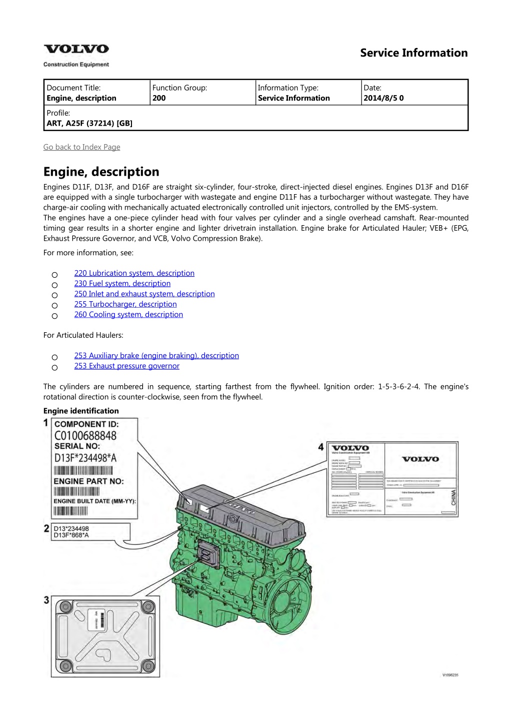
Service Information Document Title: Engine, description Function Group: 200 Information Type: Service Information Date: 2014/8/5 0 Profile: ART, A25F (37214) [GB] Go back to Index Page Engine, description Engines D11F, D13F, and D16F are straight six-cylinder, four-stroke, direct-injected diesel engines. Engines D13F and D16F are equipped with a single turbocharger with wastegate and engine D11F has a turbocharger without wastegate. They have charge-air cooling with mechanically actuated electronically controlled unit injectors, controlled by the EMS-system. The engines have a one-piece cylinder head with four valves per cylinder and a single overhead camshaft. Rear-mounted timing gear results in a shorter engine and lighter drivetrain installation. Engine brake for Articulated Hauler; VEB+ (EPG, Exhaust Pressure Governor, and VCB, Volvo Compression Brake). For more information, see: 220 Lubrication system, description 230 Fuel system, description 250 Inlet and exhaust system, description 255 Turbocharger, description 260 Cooling system, description For Articulated Haulers: 253 Auxiliary brake (engine braking), description 253 Exhaust pressure governor The cylinders are numbered in sequence, starting farthest from the flywheel. Ignition order: 1-5-3-6-2-4. The engine's rotational direction is counter-clockwise, seen from the flywheel. Engine identification
Figure 1 Identification plates, D13F Identification plate 1 A label located on the valve cover showing the engine's component ID-number, serial number, manufacturing site, engine part number, and engine build date, as well as their bar codes. Manufacturing sites: A = Sk vde, Sweden E = Curitiba, Brazil F = Flen, Sweden L = Lyon, France Identification plate 2 The engine's serial number, part number, and manufacturing site are stamped into the engine's cylinder block. Identification plate 3 The hardware component number of the Engine Control Unit (ECU) is located on a label on the back of the ECU. Identification plate 4 The certification label is located on the valve cover as well as the machine's frame. Automatic Engine Shutdown This is a function used to automatically shut down the engine after idling for a certain time. The operator is informed and has the opportunity to cancel the function within one minute, either by increasing the engine speed, shifting gear, or by activating the hand throttle. Engine protection The ECU contains functionality designed to protect the engine from damage during extreme operating conditions or from further damage when an essential engine component fails. There are several proactive functions, and different applications have different functions activated. The ones that can be activated are: High coolant temperature High intake manifold air pressure High intake manifold air temperature High oil temperature Low oil pressure Low coolant level High crankcase pressure High ECU temperature Various protective actions such as warning lights, engine torque reduction, engine speed limitation, and vehicle speed limitation may be taken when the above functions reach dangerous levels that may damage the engine. In order to always allow the operator to move a machine away from an unsafe situation, there is a delay of at least 30 seconds before the protective actions (such as forced idle and forced shutdown) are activated after a Key-ON. If the engine has been forced to shutdown or forced to idle due to an active engine protection function, the operator can obtain a 30 second delay by powering down the EMS with a Key-OFF for 7 seconds and then a Key-ON (the EMS is powered down by the Vehicle-ECU (V-ECU) after the ignition key has been in its OFF position for approx. 7 seconds). In addition to the above protective functions, other software functions could request engine protection, such as: High Altitude (ensures that high compressor discharge temperature is never reached) Turbo OverSpeed Low Coolant Temp Crank Sensor Failure Gear Ratio Warning lights There are two levels for warning lights, an amber caution light and a red stop light. The amber light indicates a warning situation The red light indicates that the vehicle must be stopped. Engine torque limitation The engine torque can be limited by the engine protection function. Engine torque limitation is active until the parameter
has reached a safe level or until the EMS is powered down. Forced Idle The engine can be forced to idle speed by the engine protection function. Forced idle is active until conditions triggering the problem are back within normal working range or the EMS is powered down. Engine Shutdown The engine can be forced to shut down after conditions have reached levels that may cause engine failure and the machine speed is below a specified value. Machine Speed and Engine Speed Limits The engine protection function can limit the speed of the vehicle and/or the engine's rpm. Levels of engine protection Available proactive functions depend not only on the application but also on what level of protection has been activated for the specific machine. Two levels of engine protection are offered, the standard level is Basic protection and the optional level Extended protection. The general difference between basic and extended engine protection is that no active actions such as forced idle and forced shutdown will be taken in basic engine protection (with the exception of crankcase pressure that can cause shutdown in either setup). Warnings will be given to the operator regardless of engine protection level. Parameters (ATJ) Injector cylinder 1, calibration (ATK) Injector cylinder 2, calibration (ATL) Injector cylinder 3, calibration (ATM) Injector cylinder 4, calibration (ATN) Injector cylinder 5, calibration (ATO) Injector cylinder 6, calibration (FAU) Automatic engine shut off (FAV) Automatic engine shut off, time (YA) Idle speed, setting Supplementary information 200 Component locations Function check 17030-3 Parameter, programming Diagnostics Detailed information about the following relevant warnings and error codes is available under the diagnostics tab. Component EF2117 (ART) PPID55 (WLO, EXC) SE2202 FX1006 (WLO) SE2507 FX1007 (WLO) SE2203 SE2509 SE2603 SE2606 Control unit MID128 Message ID PPID55 MID128 PID175 MID128 PID105 MID128 MID128 MID128 MID128 PID100 PID153 PID111 PID110
https://www.ebooklibonline.com Hello dear friend! Thank you very much for reading. Enter the link into your browser. The full manual is available for immediate download. https://www.ebooklibonline.com
Service Information Document Title: Engine, description Function Group: 200 Information Type: Service Information Date: 2014/8/5 0 Profile: ART, A25F (37214) [GB] Go back to Index Page Engine, description Engines D11H, D13H, and D16H are straight six-cylinder, four-stroke, direct-injected diesel engines. They are equipped with a single variable geometry turbocharger (VGT) and feature cooled external exhaust gas recirculation (EGR). They have charge-air cooling with mechanically actuated electronically controlled unit injectors, controlled by the EMS-system. The engines have a one-piece cylinder head with four valves per cylinder and a single overhead camshaft. Rear-mounted timing gear results in a shorter engine and lighter drivetrain installation. The engine brake for articulated haulers, VEB7, does not have the additional Exhaust Pressure Governor, EPG. Sufficient exhaust back-pressure will be controlled via the VGT. For more information, see: 220 Lubrication system, description 230 Fuel system, description 250 Inlet and exhaust system, description 254 Exhaust Aftertreatment System, description 255 Turbocharger, description 260 Cooling system, description 293 Exhaust Gas Recirculation (EGR), description For Articulated Haulers: 253 Auxiliary brake (engine braking), description The cylinders are numbered in sequence, starting farthest from the flywheel. Ignition order: 1-5-3-6-2-4. The engine's rotational direction is counter-clockwise, seen from the flywheel. Engine identification
Figure 1 Identification plates, D13H Identification plate 1 A label located on the valve cover showing the engine's component ID-number, serial number, manufacturing site, engine part number, and engine build date, as well as their bar codes. Manufacturing sites: A = Sk vde, Sweden E = Curitiba, Brazil F = Flen, Sweden L = Lyon, France Identification plate 2 The engine's serial number, part number, and manufacturing site are stamped into the engine's cylinder block. Identification plate 3 The hardware component number of the Engine Control Unit (ECU) is located on a label on the back of the ECU. Identification plate 4 The certification label is located on the valve cover as well as the machine's frame. Automatic Engine Shutdown This is a function used to automatically shut down the engine after idling for a certain time. The operator is informed and has the opportunity to cancel the function within one minute, either by increasing the engine speed, shifting gear, or by activating the hand throttle. Engine protection The ECU contains functionality designed to protect the engine from damage during extreme operating conditions or from further damage when an essential engine component fails. There are several proactive functions, and different applications have different functions activated. The ones that can be activated are: High coolant temperature
High intake manifold air pressure High intake manifold air temperature High oil temperature Low oil pressure Low coolant level High temperature of cooled EGR exhausts after the EGR-cooler High crankcase pressure Variable Geometry Turbo valve and position error High temperature of Smart Remote Actuator High compressor charge-air temperature (calculated) High soot load High differential pressure across Diesel Particulate Filter (DPF) High exhaust temperature High ECU temperature High DPF temperature Various protective actions such as warning lights, engine torque reduction, engine speed limitation, and vehicle speed limitation may be taken when the above functions reach dangerous levels that may damage the engine. In order to always allow the operator to move a machine away from an unsafe situation, there is a delay of at least 30 seconds before the protective actions (such as forced idle and forced shutdown) are activated after a Key-ON. If the engine has been forced to shutdown or forced to idle due to an active engine protection function, the operator can obtain a 30 second delay by powering down the EMS with a Key-OFF for 7 seconds and then a Key-ON (the EMS is powered down by the Vehicle-ECU (V-ECU) after the ignition key has been in its OFF position for approx. 7 seconds). In addition to the above protective functions, other software functions could request engine protection, such as: High Altitude (ensures that high compressor charge-air temperature is never reached) Turbo OverSpeed Low Coolant Temp Crank Sensor Failure Gear Ratio Regeneration Warning lights There are two levels for warning lights, an amber caution light and a red stop light. The amber light indicates a warning situation The red light indicates that the vehicle must be stopped. Engine torque limitation The engine torque can be limited by the engine protection function. Engine torque limitation is active until the parameter has reached a safe level or until the EMS is powered down. Forced Idle The engine can be forced to idle speed by the engine protection function. Forced idle is active until conditions triggering the problem are back within normal working range or the EMS is powered down. Engine Shutdown The engine can be forced to shut down after conditions have reached levels that may cause engine failure and the machine speed is below a specified value. Machine Speed and Engine Speed Limits The engine protection function can limit the speed of the vehicle and/or the engine's rpm. Levels of engine protection Available proactive functions depend not only on the application but also on what level of protection has been activated for the specific machine. Two levels of engine protection are offered, the standard level is Basic protection and the optional level Extended protection. The general difference between basic and extended engine protection is that no active actions such as forced idle and forced shutdown will be taken in basic engine protection (with the exception of crankcase pressure that can cause shutdown in either setup). Warnings will be given to the operator regardless of engine protection level. Parameters (FAU) Automatic engine shut off (FAV) Automatic engine shut off, time
(JVL) Injector cylinder 1, calibration E3 Glitch Trim (JVM) Injector cylinder 2, calibration E3 Glitch Trim (JVN) Injector cylinder 3, calibration E3 Glitch Trim (JVO) Injector cylinder 4, calibration E3 Glitch Trim (JVP) Injector cylinder 5, calibration E3 Glitch Trim (JVQ) Injector cylinder 6, calibration E3 Glitch Trim (YA) Idle speed, setting Supplementary information 200 Component locations Function check 17030-3 Parameter, programming Diagnostics Detailed information about the following relevant warnings and error codes is available under the diagnostics tab. Component EF2112 (ART) PID404 (EXC, WLO) EF2117 (ART) PPID55 (WLO, EXC) EF2127 (ART) PPID89 (EXC, WLO) EF2515 (ART) PSID28 (WLO, EXC) EF2525 (ART) PID173 (EXC) SE2510 (WLO) SE2202 FX1006 (WLO) SE2507 FX1007 (WLO) MO2501 PPID326 (WLO, EXC) SE2203 SE2509 SE2516 SE2519 SE2603 SE2606 Control unit MID128 Message ID PID404 MID128 PPID55 MID128 PPID89 MID128 PSID28 MID128 PID173 MID128 PID175 MID128 PID105 MID128 MID128 MID128 MID128 MID128 MID128 MID128 MID128 SID27 PPID326 PID100 PID153 PID412 PID81 PID111 PID110
Service Information Document Title: Engine, sensor positions Function Group: 200 Information Type: Service Information Date: 2014/8/5 0 Profile: ART, A25F (37214) [GB] Engine, sensor positions Control unit sensors This is a brief description of the sensors that are found on the engine. Figure 1 1. 2. 3. 4. 5. 6. 7. Sensor for crankcase pressure, SE2509 Sensor for charge-air temperature, SE2512 (only engine with EGR) Sensor for boost pressure/charge-air temperature, SE2507/SE2508 FX1007 Tachometer sensor, flywheel, SE2701 Sensor for coolant temperature, cooling circuit engine/retarder, SE2602 Sensor for coolant temperature, cooling circuit converter, SE2601 Sensor for oil level/oil temperature, SE2205/SE2202 FX1006
Figure 2 1. 2. 3. 4. 5. 6. 7. 8. 9. Sensor for coolant level, SE2603 Speed sensor (rpm), turbocharger SE2514 Temperature sensor EGR SE2516 Sensor, coolant temperature SE2606 Sensor, EGR-flow SE2515 Sensor for oil pressure, SE2203 Sensor for water indicator, SE2302 Sensor for fuel pressure, SE2301 Camshaft sensor, engine position, SE2703 Sensor for air pressure/air temperature, SE2501/SE2502 FX1008 10.
Service Information Document Title: Engine, identification Function Group: 200 Information Type: Service Information Date: 2014/8/5 0 Profile: ART, A25F (37214) [GB] Engine, identification Identification plate 1 A decal with the software's ID-number, the engine's serial number and assembly plant is located on the valve cover to ensure installation of correct ECU on the engine in production. On the back of the ECU, there is a decal indicating its hardware number. Identification plate 2 Engine designation, serial number, part number and assembly plant are stamped in one field on the engine block's left front edge. Assembly plants: A = Sk vde, Sweden E = Curitiba, Brazil F = Flen, Sweden L = Lyon, France Identification plate 3 The engine control unit (ECU) has its component number on a plate on the back. Identification plate 4 The certification decal is located on the valve cover as well as on the left side of the machine's front frame. Figure 1 Product plate
Figure 2 Engine versions In order to offer machines with lower environmental impact, two main engine types have been developed for machines in the F-series. One version developed for generally available fuel and oil grades, and a version that meets higher emission requirements. The easiest way to see on the machine what version it is, check if it has a diesel particle filter (Diesel Particulate Filter) in the muffler. See: 254 Exhaust Aftertreatment System, description . Machine A25F A25F A30F A30F A35F A35F A40F A40F Engine designation D11F D11H D11F D11H D13F D13H D16F D16H Diesel Particulate Filter No Yes No Yes No Yes No Yes
Service Information Document Title: VCADS Pro, Operations Function Group: 200 Information Type: Service Information Date: 2014/8/5 0 Profile: ART, A25F (37214) [GB] VCADS Pro, Operations The following VCADS Pro operations are available for function group 2. Operations used when changing or working on components are mandatory. NOTE! Operations used when changing or repairing components are mandatory. NOTE! New operations are developed regularly. For a current list of all tests, see VCADS Pro software. Tests Operation 20046-3 Read out engine information Application The test is used to read out engine emissions and engine certification information. The test shows whether the compression of any cylinder differs from that of the other cylinders. The test shows whether fuel injection on any cylinder differs from that on the other cylinders. The test is used to check feed pressure. The test supplements cylinder balancing. In the test, one injector at a time can be turned off manually. The test is used to check cut-in and cut-out of the air pump for the exhaust aftertreatment system. The test is used to diagnose the exhaust aftertreatment system. The test activates the built-in diagnostic function in the control unit. The test indicates any failure with a red light. Read out error codes with operation 17012-3, Error codes. This subtest is used to check function of the atomization unit's air valve, main air valve, the fuel's shut-off valve, and the fuel pump. The test is used to purge any air in the fuel system for the atomization unit. The test is used to adjust the fuel pressure in the atomization unit. The test is used to check status of the included components for the exhaust aftertreatment. This operation is used when the soot load is above 1.7, see 254 Exhaust Aftertreatment System, description In this operation, status and a number of sensor values can be read out during on-going regeneration. Also check that "DPF differential pressure" is within permitted values, both before and after 254 Exhaust aftertreatment system, specifications 21006-3 Cylinder compression, test 23016-3 Cylinder balancing, test 23017-3 Feed pressure, inspection 23712-3 Injectors shut off, manual 25410-3 Air pump exhaust aftertreatment, test 25411-3 Burner exhaust aftertreatment, test 25412-3 Components ASU, test 25433-3 Fuel system exhaust aftertreatment, bleeding 25434-3 Atomization unit, fuel pressure, adjust 25456-3 Exhaust aftertreatment diagnostics 25457-3 Regeneration Diesel Particulate Filter Service . regeneration, . see 25537-3 Variable geometry turbo function test The test is used to check function of the variable geometry turbo (VGT). The test controls the cooling fans' speed control (independent of ordinary control) and is used when adjusting speed. The test is used to check function of the throttle pedal. 26351-3 Hydraulic cooling fan, test 27102-3 Accelerator pedal, test
28407-3 Sensor values, monitoring The tests show values (temperature, rpm, etc.) that the system receives from connected sensors and monitors. The test is used to use an oscilloscope to check signals from the flywheel and camshaft position sensors. The test is used to check function of the exhaust gas recirculation. 28420-3 Flywheel and camshaft signal, test 29332-3 Exhaust gas circulation, function test Calibrations Operation 25536-3 Variable geometry turbo, calibration Application When 255 Actuator, variable turbocharger, replacing changing actuator, . see Programming Operation 25801-3 MID 233 Control unit, programming Application When changing control unit or when reprogramming complete or part of the software. Use for campaign programming of the control unit. Use for campaign programming of the control unit. When changing control unit or when reprogramming complete or part of the software. 25802-3 MID 233 Control unit, campaign 28422-3 MID 128 ECU, campaign 28423-3 MID 128 ECU, programming
Service Information Document Title: E-ECU, MID 128, changing pre-programmed ECU Function Group: 200 Information Type: Service Information Date: 2014/8/5 0 Profile: ART, A25F (37214) [GB] E-ECU, MID 128, changing pre-programmed ECU Op nbr 200-070 This operation also includes required tools and times for applicable parts of the following operations: 191 Service positions 200 E-ECU, MID 128, changing non-programmed ECU 191 Service positions 1. Place the machine in service position, see . 2. Connect VCADS Pro computer and perform 17030-3 Parameter, programming. Use the function: Save all read parameters to job card. 200 E-ECU, MID 128, changing non-programmed ECU 3. Run from and including step 3 and on. 4. Connect VCADS Pro computer and perform 17030-3 Parameter, programming. Program earlier read-out parameters according to the job card. 5. Restore the machine to operating condition.
Service Information Document Title: E-ECU, MID 128, changing non-programmed ECU Function Group: 200 Information Type: Service Information Date: 2014/8/5 0 Profile: ART, A25F (37214) [GB] E-ECU, MID 128, changing non-programmed ECU Op nbr 200-068 This operation also includes the tools and times needed for required parts of the following actions: 191 Service positions 191 Service positions 1. Place the machine in service position, see . 2. Connect VCADS Pro computer and perform 28423-3 MID 128 ECU, programming. When instructed to connect the new control unit, perform steps 3-21. CAUTION Always follow instructions according to Electrical system, work instructions, electronic components 3001 Electrical system, special instructions for servicing, electronic components CAUTION Always follow instructions according to Electrical system, work instructions, electronic components 3. Removing Open the engine hood. 4. Turn off the main electric power with the battery disconnector. 5. Disconnect the radiator from its front bracket. Swing out the radiator for easier access to the control unit. NOTE! Protect the charge-air cooler with a cloth or board. 6. Remove the screws, which releases the clamps from the E-ECU. 7. Unplug the connectors EA (7), EB (8), and EI (4).
Figure 1 E-ECU 1. 2. 3. 4. 5. 6. 7. 8. Oil separator Pressure-oil line E-ECU Connector EI Cooling unit Fuel hoses Connector EA Connector EB 8. Loosen the pressure-oil line (2) from the oil separator (1). 9. Cut the cable ties on the fuel hoses (6). NOTE! Note grouping (bunching) of the hoses to facilitate installation. 10. Loosen the cooling unit (5) from the E-ECU (6 bolts). Carefully move aside the cooling unit. NOTE! Work carefully so that hoses for the cooler are not damaged. 11. Remove the E-ECU. 12. Installing Fit the E-ECU. 13. Connect the cooling unit (5) to the E-ECU. Figure 2
E-ECU 1. 2. 3. 4. 5. 6. 7. 8. Oil separator Pressure-oil line E-ECU Connector EI Cooling unit Fuel hoses Connector EA Connector EB 14. Connect the pressure-oil line (2) to the oil separator (1). 15. Connect the connectors EA (7), EB (8), and EI (4). 16. Install the screws that fasten the clamps to the E-ECU. 17. Fasten the fuel hoses (6) according to earlier notes. 18. Connect the radiator to the front bracket. 19. Close the engine hood. NOTE! When changing pre-programmed control unit, go back to 200 E-ECU, MID 128, changing pre-programmed ECU step 4. 20. Finish VCADS Pro operation 28423-3 MID 128 ECU, programming. 21. Restore the machine to operating condition.
Service Information Document Title: Cylinder compression, PC test Function Group: 210 Information Type: Service Information Date: 2014/8/5 0 Profile: ART, A25F (37214) [GB] Cylinder compression, PC test Connect the VCADS Pro computer and carry out 21006-3 Cylinder compression, test. (21006-3) This test indicates if there is any deviation in compression in any cylinder in relation to the other cylinders.
Service Information Document Title: Engine and transmission, removing Function Group: 210 Information Type: Service Information Date: 2014/8/5 0 Profile: ART, A25F (37214) [GB] Engine and transmission, removing Op nbr 210-073 This operation also includes required tools and times for applicable parts of the following operations: 191 Service positions 173 Coolant, changing 900 Vacuum pump, connection 715 Protective plate, removing WARNING Changing control units between machines, when troubleshooting or repairing, may not take place for any reason without reprogramming. Incorrect individual settings in the control unit may result in personal injury or machine damage. For reprogramming and read-out of software, see "VCADS Pro User manual". 1. Place the machine in service position, see 191 Service positions 2. Swing down the front grill and open the engine hood. Figure 1 3. Turn off the electric power with the battery disconnect switch. 715 Protective plate, removing 4. Remove the front and rear underbody skid plates. See .
Figure 2 1. 2. 3. 4. 5. Front underbody skid plate Rear underbody skid plate, left Rear underbody skid plate, right Front cross member Rear cross member 5. Remove the front and rear cross members. Weight: approx.15 kg (33 lbs). WARNING Risk of burns. The fluid may be hot. 6. NOTE! Take care of waste oil/fluids in an environmentally sound manner. NOTE! The oil drain hose is inserted in the pipe for the ladder on the inside of the front grill. Drain the gearbox oil. Volume, see: 400 Drive train capacities Figure 3 Draining transmission oil 7. Drain the coolant, see: 173 Coolant, changing Work in engine compartment 8. Remove the front protective plates and the belt guard.
Figure 4 9. Remove the bolt and swing out the radiator. Figure 5 NOTE! Keep in mind that the cooling fins are easily damaged. To protect them, install a sheet of plywood or similar. 10. Loosen the belt tensioners with a half inch ratchet handle and remove the three belts. Figure 6
11. Loosen and remove the connections for the preheating coil and the pipe for compressed air from the compressor. Remove the coolant hoses and the joint. Remove the compressor's signal line. Figure 7 1. 2. 3. 4. 5. Compressed air pipe Plus cable Joint Lower coolant hose Upper coolant hose 12. Unplug the connector (EL). Remove the cable clamp. Figure 8 WARNING Do not disconnect or loosen connections for the air conditioning unit (AC). Risk of gas leakage. 13. Unplug the connector for control current to the AC compressor. Remove the bolts and remove the AC compressor. Put it aside.
Suggest: If the above button click is invalid. Please download this document first, and then click the above link to download the complete manual. Thank you so much for reading
Figure 9 14. Remove the alternator's ground cable. 15. Loosen the connections for the temperature sensors. Remove the upper and lower cooling hoses from the secondary coolant pump. Figure 10 View from below 1. 2. Temperature sensor primary circuit , SE 2602 Temperature sensor secondary circuit, SE 2601 16. Remove the secondary pump. 17. Loosen the hoses for the expansion tank. Unplug the level sensor's connector SE 2603 down on the expansion tank. Loosen the four bolts for the foot step and lift it away. Figure 11
https://www.ebooklibonline.com Hello dear friend! Thank you very much for reading. Enter the link into your browser. The full manual is available for immediate download. https://www.ebooklibonline.com


 Injector cylinder 1, calibration E3 Glitch Trim")