Volvo A25E Articulated Dump Truck Service Repair Manual Instant Download
Please open the website below to get the complete manualnn// n

Download Presentation

Please find below an Image/Link to download the presentation.
The content on the website is provided AS IS for your information and personal use only. It may not be sold, licensed, or shared on other websites without obtaining consent from the author. Download presentation by click this link. If you encounter any issues during the download, it is possible that the publisher has removed the file from their server.
E N D
Presentation Transcript
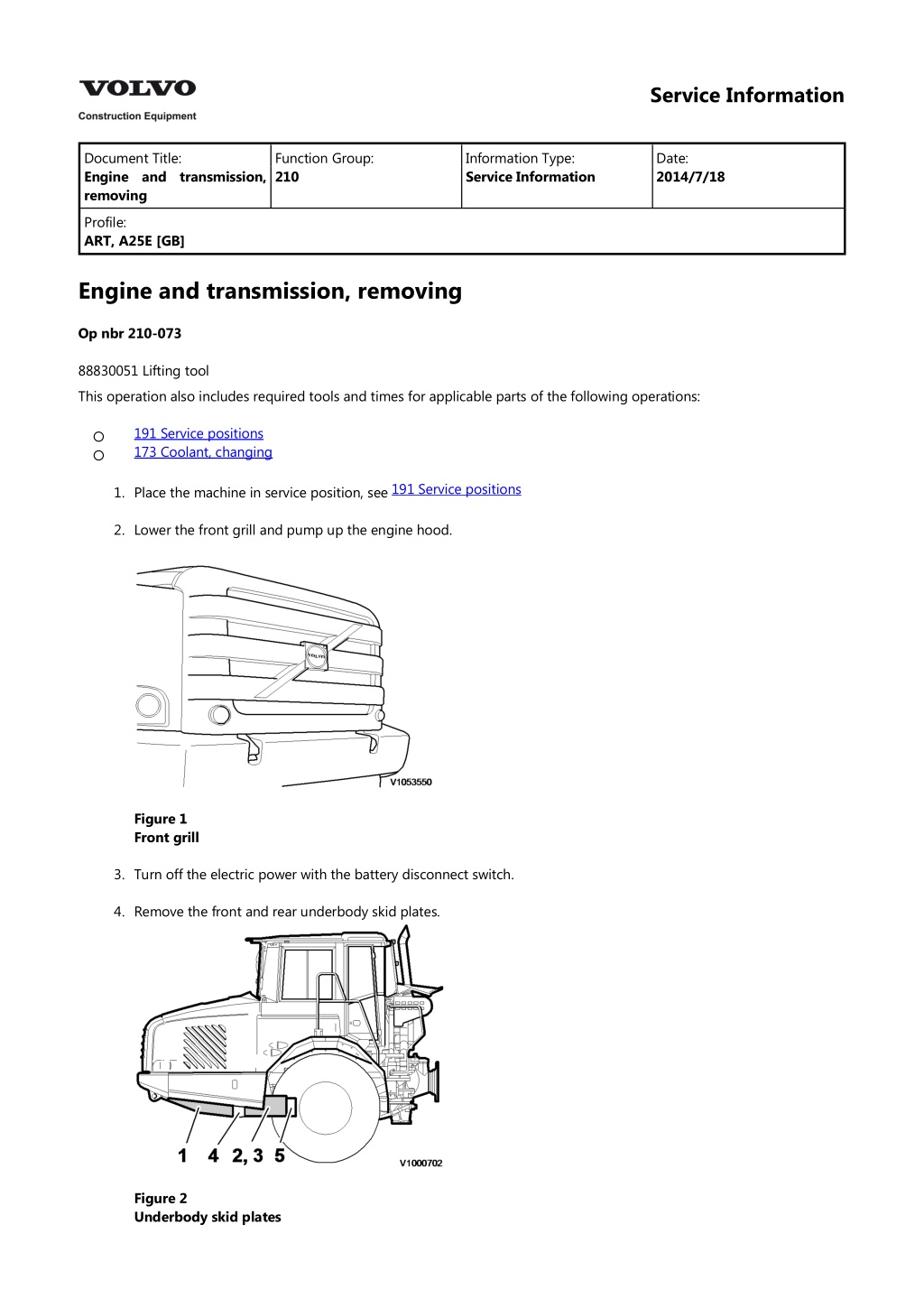
Service Information Document Title: Engine and transmission, removing Function Group: 210 Information Type: Service Information Date: 2014/7/18 Profile: ART, A25E [GB] Engine and transmission, removing Op nbr 210-073 88830051 Lifting tool This operation also includes required tools and times for applicable parts of the following operations: 191 Service positions 173 Coolant, changing 1. Place the machine in service position, see 191 Service positions 2. Lower the front grill and pump up the engine hood. Figure 1 Front grill 3. Turn off the electric power with the battery disconnect switch. 4. Remove the front and rear underbody skid plates. Figure 2 Underbody skid plates
1. 2. 3. 4. 5. Front underbody skid plate Rear underbody skid plate, left Rear underbody skid plate, right Front cross member Rear cross member 5. Remove the front and rear cross members. Weight: approx.15 kg (33 lbs). 6. Drain the hydraulic oil tank. Volume, see 030 Capacities The drain nipple is located on the middle of the tank by the suction line for the front hydraulic pumps. NOTE! The oil drain hose is inserted in the pipe for the ladder on the inside of the front grill. Figure 3 Draining hydraulic oil tank WARNING Risk of burns. The fluid may be hot. 7. Drain the engine oil. Volume, see 030 Capacities Figure 4 Draining engine oil 8. Drain the gearbox oil. Volume, see Capacities
Figure 5 Draining transmission oil 9. Remove the cap for the expansion tank. Figure 6 10. Drain the coolant, see: 173 Coolant, changing 11. When the expansion tank is empty, open the air bleeder nipples on the cooling pipes. Figure 7 1. Air bleeder nipples 12. Disconnect the drain hose from the oil sump. Plug and fold it aside.
https://www.ebooklibonline.com Hello dear friend! Thank you very much for reading. Enter the link into your browser. The full manual is available for immediate download. https://www.ebooklibonline.com
Figure 8 13. Mark up and unplug the connectors for the PWM-valves, PWM2601 and PWM2602, on the fan pumps. Figure 9 14. Disconnect the suction hoses (3 pcs.) between the hydraulic tank and the pumps. NOTE! Take care of waste oil and liquids in an environmentally safe way. 15. Remove the cannon connector from the transmission's connector (EH). Remove the main oil filter with the bracket. NOTICE Protect all surfaces with plastic film or similar. Figure 10 1. 2. Cannon connector Main oil filter with holder
16. Remove the LS-hoses (2 pcs.) and the connector for solenoid valve MA9102 See figure. LS-hose 2 is disconnected on the left rear pump. Remove the valve block. Figure 11 1. 2. Solenoid valve MA9102 LS-hose 1 17. Remove the connectors for temperature sensor SE4204 and PWM4204 from the retarder valve. Figure 12 1. 2. SE4204 PWM4204 18. Unplug the connector for sensor SE4307 for output speed from the transmission's rear cover.
Figure 13 1. Rpm sensor SE4307 19. Unplug connectors for temperature sensors SE2601 and SE2602. SE2601 is located at the engine's left front edge and SE2602 is located at the engine's right front edge. 20. Remove the belt guard. Figure 14 21. Remove the bolt for the front radiator bracket. Figure 15 22. Remove the outer screw for the headlight, and swing out the headlight and the radiator.
Figure 16 23. Disconnect and plug the radiator hoses between the engine and the radiator. Figure 17 24. Disconnect connections AL3201, AL3201 B+ and the ground cable from the alternator and unplug connector MA8701 for the AC compressor. Figure 18
1. 2. 3. 4. AL3201 AL3201/B2+ Ground cable MA8701 WARNING See "Safety when working with air conditioning", section S and Service Manual "Air conditioning R134a". 25. If the machine is equipped with AC, the belt tensioner and compressor have to be removed. Pull the compressor slightly forward, then tilt it up and back, leave the hoses for the cooling system in place on the compressor to avoid refrigerant leaks. 26. Unplug the connector for sensor SE2603 from the expansion tank and remove the expansion tank with the bracket. The bolts for the bracket are located on the inside of the radiator bow. Figure 19 1. Connector SE2603 27. Disconnect the cable connection from the preheating coil as well as the feed line and signal line from the compressor. Figure 20 1. 2. 3. Cable connection Feed line Signal line
28. Disconnect the cable connections RE2501 from the preheating relay. Figure 21 29. Remove the connector EM from the control unit's cable harness quick-coupling. Figure 22 1. Connector 30. Remove the upper connection to the intercooler. NOTICE Always cover open air connections with a plastic bag and rubber bands. Gravel, dust and other particles in these connections may result in engine failure! Figure 23
31. Unplug the connector SE2501/2502 from the sensor on the inlet pipe. Remove the inlet pipe for the compressor. Figure 24 1. 2. Sensor SE2501/2502 Inlet pipe for compressor 32. Remove the induction hose for the turbo. NOTICE Always cover open air connections with a plastic bag and rubber bands. Gravel, dust and other particles in these connections may result in engine failure! Figure 25 33. Remove the inlet pipe for the turbo. NOTICE Always cover open air connections with a plastic bag and rubber bands. Gravel, dust and other particles in these connections may result in engine failure!
Figure 26 34. Disconnect and plug the fuel hoses. Figure 27 35. Unplug connectors MA2308/SE2301 and MA2309/SE2302 from the fuel filter bracket. 36. Disconnect the connector EWM2501 from the air valve to the EP-governor. 37. Remove the turbine housing with the EP-governor. NOTICE Always cover open air connections with a plastic bag and rubber bands. Gravel, dust and other particles in these connections may result in engine failure! Figure 28
1. 2. 3. Clamp against exhaust pipe Clamp against turbo housing Connection pipe EP-governor 38. Mark up and disconnect the radiator hoses for cab heat and the radiator hose. Figure 29 1. 2. 3. Radiator hose for cab heat Radiator hose for cab heat Radiator hose 39. Disconnect the radiator hose on the engine's left side. Figure 30 Work in cab 40. Remove the floor mat. 41. Disconnect air and electrical connections from the operator's seat. 42. Remove the operator seat. Weight: 40 kg (88 lbs). 43. Remove the rear and the middle floor plates. Weight: 25 kg (55 lbs).
44. Remove the plastic cover from the steering column. Figure 31 45. Remove the steering column UJ locking pin. Remove the bolt and separate the steering column. Figure 32 46. Loosen and move aside the retarder pedal, throttle pedal and diff lock switch SW4604. Figure 33 47. Loosen and press down the brake pedal through the front floor plate without disconnecting the air connections.
Figure 34 48. Mark the position of the steering shaft in relation to the steering gear. Bend down the striker plates and remove the 2 bolts. Remove the steering shaft from the steering shaft's flange. Figure 35 49. Make sure that the steering shaft cannot come apart. Use cable ties or similar. NOTE! It's important to maintain the relative position of the universal joints. Figure 36 50. Remove the front floor plate. 51. Unplug and mark up the connectors for the brake pedal.
Figure 37 1. 2. 3. 4. SW5205 SE5202 SE5204 SE5203 52. Loosen the propeller shaft from the transmission. Suspend the propeller shaft in a tensioning strap so that it doesn't fall down. Figure 38 53. Open the battery compartment and pull out the transmission dipstick. 54. Disconnect the oil filler hose and the pipe for the oil level dipstick from the transmission. Figure 39
1. 2. Pipe, oil level dipstick Oil filler hose 55. Disconnect the breather hose from the transmission. Figure 40 56. Remove the clamp on the exhaust pipe at the transmission's trailing edge. Figure 41 57. Remove the exhaust pipe's front attachment against the frame. Figure 42
1. Front attachment WARNING Risk of crushing injuries 58. Raise the front grill and remove the lock pin and pin for the gas springs. Disconnect the gas springs from the bows and lower them. NOTE! Do not walk on the steps when the gas springs are removed from the bows. Figure 43 1. Engine bows 59. Disconnect the front engine bows and fold them aside. 60. Remove the exhaust pipe. Figure 44 61. Remove the lower gaiter between the intercooler and turbo. NOTICE Always cover open air connections with a plastic bag and rubber bands. Gravel, dust and other particles in these connections may result in engine failure!
Figure 45 62. Mark up and disconnect all cabling from the starter motor. Figure 46 63. Secure the engine and transmission with 88830051 Lifting tool. Weight: approx. 1900 kg (4190 lbs). Figure 47
Suggest: If the above button click is invalid. Please download this document first, and then click the above link to download the complete manual. Thank you so much for reading
64. Remove the bolts for the front engine mount. 65. Remove the bolted joints for the rear engine mounts, and remove the engine mounts. Figure 48 66. Lift the engine and transmission carefully. Due to the cramped space between the oil sump and frame, the engine must be tilted at the rear at the start of the lift. NOTE! Check that no hoses or cables are damaged. Figure 49 67. Lift out the engine and transmission and place the engine on three axle stands. Weight: approx.1900 kg (4180 lbs).
https://www.ebooklibonline.com Hello dear friend! Thank you very much for reading. Enter the link into your browser. The full manual is available for immediate download. https://www.ebooklibonline.com


 and the connector for")