Volvo A25E 4x4 Articulated Dump Truck Service Repair Manual Instant Download
Please open the website below to get the complete manualnn// n

Download Presentation

Please find below an Image/Link to download the presentation.
The content on the website is provided AS IS for your information and personal use only. It may not be sold, licensed, or shared on other websites without obtaining consent from the author. Download presentation by click this link. If you encounter any issues during the download, it is possible that the publisher has removed the file from their server.
E N D
Presentation Transcript
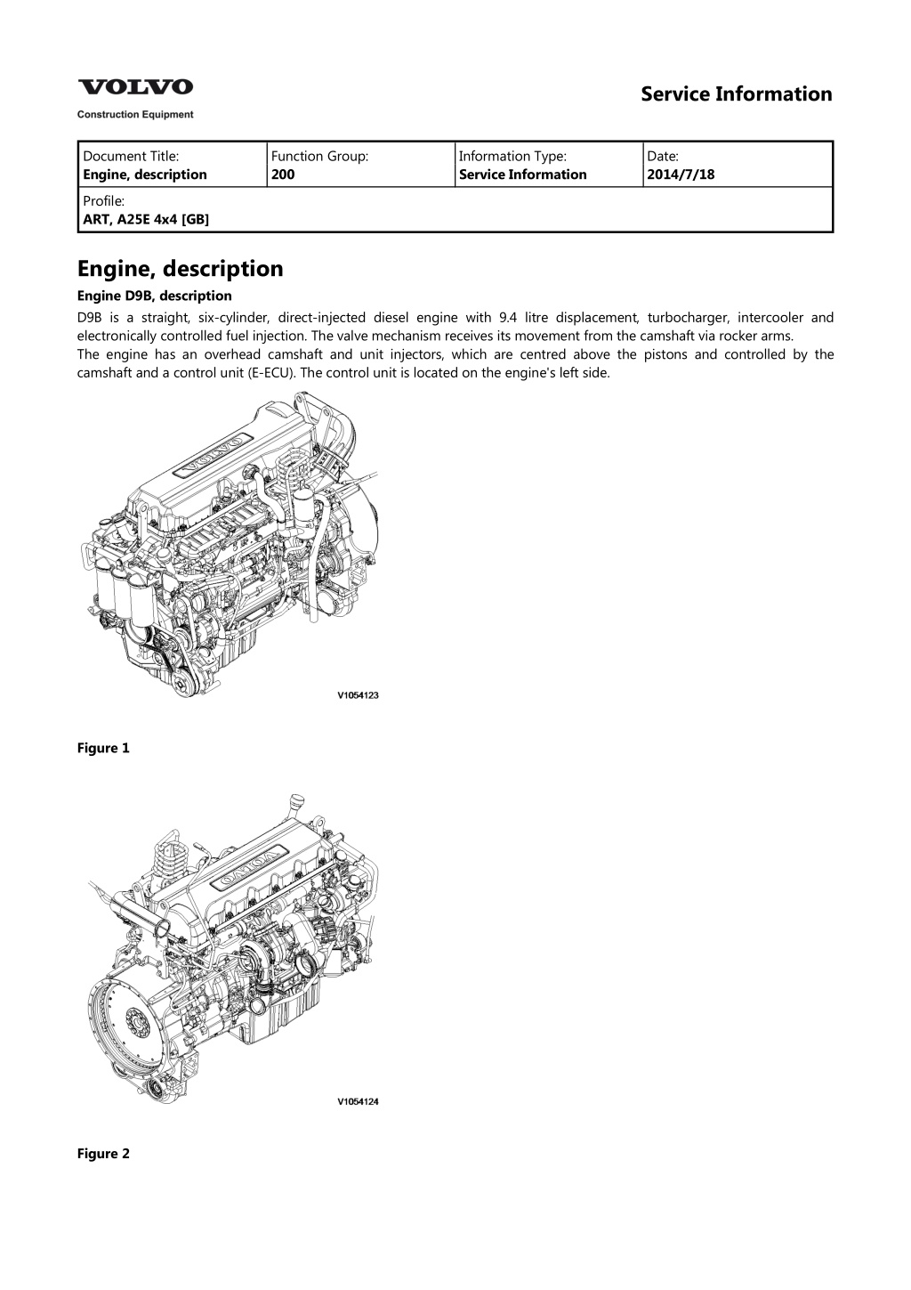
Service Information Document Title: Engine, description Function Group: 200 Information Type: Service Information Date: 2014/7/18 Profile: ART, A25E 4x4 [GB] Engine, description Engine D9B, description D9B is a straight, six-cylinder, direct-injected diesel engine with 9.4 litre displacement, turbocharger, intercooler and electronically controlled fuel injection. The valve mechanism receives its movement from the camshaft via rocker arms. The engine has an overhead camshaft and unit injectors, which are centred above the pistons and controlled by the camshaft and a control unit (E-ECU). The control unit is located on the engine's left side. Figure 1 Figure 2
Service Information Document Title: Engine, identification Function Group: 200 Information Type: Service Information Date: 2014/7/18 Profile: ART, A25E 4x4 [GB] Engine, identification Identification plate 1 Engine designation, serial number, part number and assembly plant are stamped in one field on the engine block's left front edge. Identification plate 2 A decal with the software's ID-number, the engine's serial number and assembly plant is located on the valve cover to ensure installation of correct ECU on the engine in production. On the back of the ECU, there is a decal indicating its hardware number. The E-ECU is located on the engine's left side. Assembly plants: A = Sk vde, Sweden E = Curitiba, Brazil F = Flen, Sweden L = Lyon, France Figure 1 Identification plate 3 The certification decal is located on the valve cover as well as on the left side, at the back of the machine's front frame inside of the steps.
Service Information Document Title: E-ECU, MID 128, changing pre-programmed ECU Function Group: 200 Information Type: Service Information Date: 2014/7/18 Profile: ART, A25E 4x4 [GB] E-ECU, MID 128, changing pre-programmed ECU Op nbr 200-070 This operation also includes required tools and times for applicable parts of the following operations: 200 E-ECU, MID 128, changing non-programmed ECU 1. Connect VCADS Pro computer and perform 17030-3 Parameter, programming. Use the function: Save all read parameters to job card. 200 E-ECU, MID 128, changing non-programmed ECU 2. Perform step 2 14. 3. Connect VCADS Pro computer and perform 17030-3 Parameter, programming. Program earlier read-out parameters according to the job card.
https://www.ebooklibonline.com Hello dear friend! Thank you very much for reading. Enter the link into your browser. The full manual is available for immediate download. https://www.ebooklibonline.com
Service Information Document Title: E-ECU, MID 128, changing non-programmed ECU Function Group: 200 Information Type: Service Information Date: 2014/7/18 Profile: ART, A25E 4x4 [GB] E-ECU, MID 128, changing non-programmed ECU Op nbr 200-068 1. Connect VCADS Pro computer and perform 28423-3 MID 128 ECU, programming When instructed to connect the new control unit, perform steps 2 15. Removing E ECU CAUTION Always follow instructions according to Electrical system, work instructions, electronic components 3001 Electrical system, special instructions for servicing, electronic components CAUTION Always follow instructions according to Electrical system, work instructions, electronic components 2. Figure 1 E-ECU 1. 2. 3. 4. 5. Connector EA Connector EB Screw for clamp Screw for cooler Screw for ECU Place the machine in service position. 3. Open the engine hood. NOTICE Turn off the electric power with the battery disconnect switch before starting any work. Also remove the
fuse for respective component. 4. Remove the three screws (3) that disconnect the clamps from the E-ECU. 5. Unplug the connectors EA and EB from the E-ECU. 6. Remove th screws (4) (6 pcs. ) that hold the cooler (3). 7. Remove the screws (5) (4 pcs.) that hold the E-ECU. 8. Carefully move aside the cooler and remove the E-ECU. NOTE! Work carefully so that hoses for the cooler are not damaged. Mounting E ECU 9. Lift in the E-ECU inside of the cooler. 10. Install the screws (5) (4 pcs.) that hold the E-ECU against the engine block. 11. Install the screws (4) (6 pcs.) that hold the cooler against the E-ECU. 12. Plug in the connectors EA and EB for the E-ECU. 13. Install the screws (3 pcs.) that hold the clamps against the E-ECU. 14. Close the engine hood. NOTE! When changing pre-programmed ECU, return to 200 E-ECU, MID 128, changing pre-programmed ECU step 3. 15. Finish VCADS Pro operation 28423-3 MID 128 ECU, programming.
Service Information Document Title: Cylinder compression, PC test Function Group: 210 Information Type: Service Information Date: 2014/7/18 Profile: ART, A25E 4x4 [GB] Cylinder compression, PC test Connect the VCADS Pro computer and carry out 21006-3 Cylinder compression, test. (21006-3) This test indicates if there is any deviation in compression in any cylinder in relation to the other cylinders.
Service Information Document Title: Compression test Function Group: 210 Information Type: Service Information Date: 2014/7/18 Profile: ART, A25E 4x4 [GB] Compression test Op nbr 210-002 9990006 Puller 9990185 Lifting tool 9996400 Impact puller 9998599 Cleaning tool 9998248 Adapter 9998248 Adapter 9998248 Adapter 9998248 Adapter 9998248 Adapter 9998248 Adapter 9993590 Gear wheel 88880003 Bracket 9988539 Pressure gauge 88820016 Setting tool This operation also includes the tools and times needed for required parts of the following actions: 191 Service positions 237 Unit injector, adjusting pretension 233 Fuel system, bleeding 214 Valves, adjusting Removing 191 Service positions 1. Place the machine in service position, see . 2. Lower the front grill and pump up the engine hood. 3. Drain the cylinder head to avoid fuel in the engine oil. Open the connection by the return line on the cylinder head and install a hose. Figure 1
4. Loosen the feed hose from the connection by the ECU. Use an air nozzle to get out all of the fuel. Lead the feed hose into a container Since the feed pump will pump out fuel during the test, the container's volume must be at least 5 litres (1.3 US gal). Figure 2 5. Secure the expansion tank with a strap, and then loosen the bracket for the expansion tank. Figure 3 6. Remove the engine's front lifting eye. This is done to enable installation of the lifting tool on the rocker arm bridge. 7. Remove the hose from the oil trap and remove the valve cover. 8. The condition for reading off correct compression pressure is that the valve clearance is correct. See: 214 Valves, adjusting 9. Remove the IEGR control valve's electrical connections and wipe clean around the control valve. Remove the valve.
Figure 4 10. Loosen the bolts for the rocker arm shaft, evenly distributed across the rocker arm shaft to avoid shear stresses. Remove the bolts. Lift away the rocker arm shaft with tool 9990185 and 88880003. Rocker arm shaft's weight: : approx. 30 kg (66 lbs) Figure 5 9990185 11. Clean very thoroughly around the unit injector. Remove the electrical connection. Remove the bolt for the attaching yoke. Remove the injector together with the attaching yoke. Use 9996400 Impact puller, 9990262 Adapter, and 9990006 Puller. Remove the other unit injectors in the same way. NOTE! Place each injector in separate new plastic bags. Mark which cylinder they were installed in. It is important to not mix up the injectors since they are classed for a certain cylinder.
Suggest: If the above button click is invalid. Please download this document first, and then click the above link to download the complete manual. Thank you so much for reading
Figure 6 1. 2. 3. 9996400, Impact hammer 9990262, Adapter 9990006, Puller 12. Clean the copper sleeve with the brush/brushes included in kit 9998599. Figure 7 1. 2. 3. Extension Brush Protective sleeve
https://www.ebooklibonline.com Hello dear friend! Thank you very much for reading. Enter the link into your browser. The full manual is available for immediate download. https://www.ebooklibonline.com