Volvo A25D Articulated Dump Truck Service Repair Manual Instant Download
Please open the website below to get the complete manualnn// n

Download Presentation

Please find below an Image/Link to download the presentation.
The content on the website is provided AS IS for your information and personal use only. It may not be sold, licensed, or shared on other websites without obtaining consent from the author. Download presentation by click this link. If you encounter any issues during the download, it is possible that the publisher has removed the file from their server.
E N D
Presentation Transcript
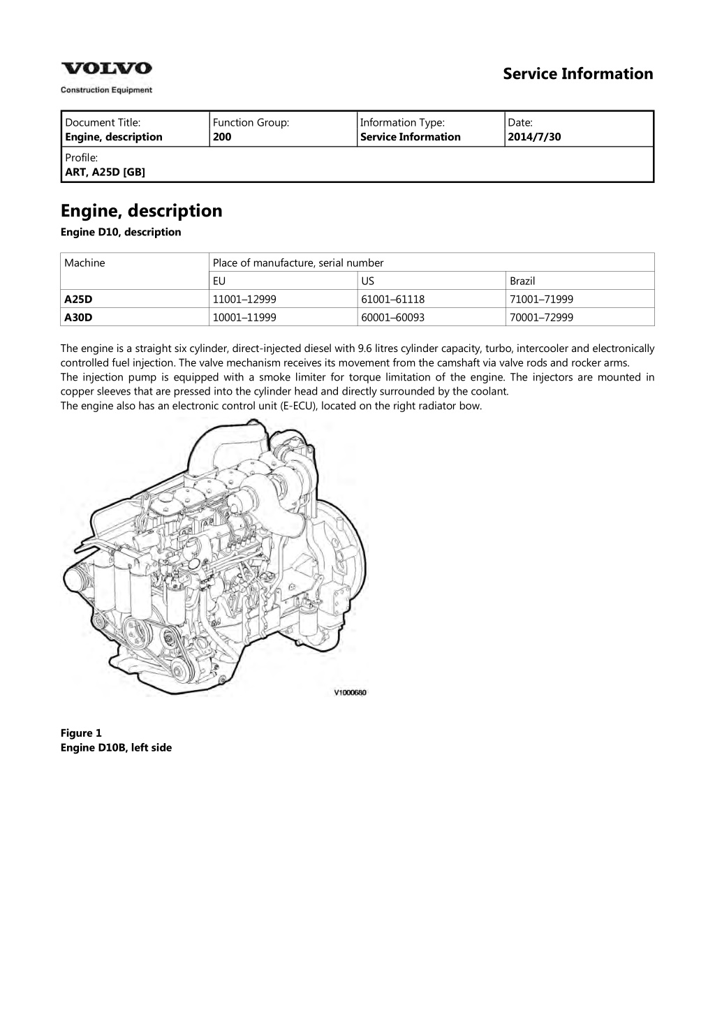
Service Information Document Title: Engine, description Function Group: 200 Information Type: Service Information Date: 2014/7/30 Profile: ART, A25D [GB] Engine, description Engine D10, description Machine Place of manufacture, serial number EU 11001 12999 10001 11999 US 61001 61118 60001 60093 Brazil 71001 71999 70001 72999 A25D A30D The engine is a straight six cylinder, direct-injected diesel with 9.6 litres cylinder capacity, turbo, intercooler and electronically controlled fuel injection. The valve mechanism receives its movement from the camshaft via valve rods and rocker arms. The injection pump is equipped with a smoke limiter for torque limitation of the engine. The injectors are mounted in copper sleeves that are pressed into the cylinder head and directly surrounded by the coolant. The engine also has an electronic control unit (E-ECU), located on the right radiator bow. Figure 1 Engine D10B, left side
Figure 2 Engine D10B, right side Engine D9, description Machine Place of manufacture, serial number EU 13001 12001 US Brazil 72000 73000 A25D A30D Engine D9 is a straight six cylinder, direct-injected diesel with 9.4 litres cylinder capacity, turbo, intercooler and electronically controlled fuel injection. The valve mechanism receives its movement from the camshaft via valve rods and rocker arms. The engine has an overhead camshaft and unit injectors, which are centred above the pistons and controlled by the camshaft and a control unit (E-ECU). The control unit is located on the engine's left side.
Figure 3 V1021882 Figure 4 V1021883
https://www.ebooklibonline.com Hello dear friend! Thank you very much for reading. Enter the link into your browser. The full manual is available for immediate download. https://www.ebooklibonline.com
Service Information Document Title: Engine, sensor positions Function Group: 200 Information Type: Service Information Date: 2014/7/30 Profile: ART, A25D [GB] Engine, sensor positions Control unit sensors The following is a brief summary of the parts on the engine. There are a number of other parts that affect the system, for example, the throttle pedal sensor. The central part of the system, the control unit is positioned on the left side of the engine. All cable connectors for the engine's sensors are of DIN standard and are connected in a so-called cable box. Figure 1 Engine D9, sensors (some have double functions) 1. 2. 3. 4. Sensor for coolant level, SE2603 Sensor for coolant temperature, cooling circuit converter, SE2601 Sensor for charge air pressure/temperature, SE2507/SE2508 Tachometer sensor, flywheel, SE2701
5. 6. 7. 8. 9. Sensor for oil level/temperature, SE2205/SE2202 Sensor for crankcase pressure, SE2509 Sensor for oil pressure, SE2203 Camshaft sensor, engine position, SE2703 Sensor for air pressure/temperature, SE2501/SE2502 Sensor for feed pressure, fuel, SE2301 Sensor for water indicator, SE2302 Sensor for coolant temperature, cooling circuit engine/retarder, SE2602 10. 11. 12.
Service Information Document Title: Engine, identification Function Group: 200 Information Type: Service Information Date: 2014/7/30 Profile: ART, A25D [GB] Engine, identification Identification plate 1 Engine designation, serial number, part number and assembly plant are stamped in one field on the engine block's left front edge. Identification plate 2 A decal with the software's ID-number, the engine's serial number and assembly plant is located on the valve cover to ensure installation of correct ECU on the engine in production. On the back of the ECU, there is a decal indicating its hardware number. The E-ECU is located on the engine's left side. Assembly plants: A = Sk vde, Sweden E = Curitiba, Brazil F = Flen, Sweden L = Lyon, France Figure 1 Identification plate 3 The certification decal is located on the valve cover as well as on the left side, at the back of the machine's front frame inside of the steps.
Service Information Document Title: E-ECU, MID 128, changing pre-programmed ECU Function Group: 200 Information Type: Service Information Date: 2014/7/30 Profile: ART, A25D [GB] Go back to Index Page E-ECU, MID 128, changing pre-programmed ECU Op nbr 200-070 Applies to machine equipped with engine D10, with serial number according to the table. Machine Place of manufacture, serial number US 61001 61118 60001 60093 EU 11001 12077 10001 10682 Brazil 70001 72999 A25D A30D 1. Connect VCADS Pro computer and perform 17030-3 Parameter, programming. Use the function Save all read parameters to job card. 200 E-ECU, MID 128, changing non-programmed ECU 2. Perform step 2 15. 3. Connect VCADS Pro computer and perform 17030-3 Parameter, programming. Program earlier read-out parameters according to the job card.
Service Information Document Title: E-ECU, MID 128, changing pre-programmed ECU Function Group: 200 Information Type: Service Information Date: 2014/7/30 Profile: ART, A25D [GB] Go back to Index Page E-ECU, MID 128, changing pre-programmed ECU Op nbr 200-070 Applies to machine equipped with engine D9A, with serial number according to the table. Machine Place of manufacture, serial number US EU 13001 12001 Brazil 73000 A25D A30D 1. Connect VCADS Pro computer and perform 17030-3 Parameter, programming. Use the function Save all read parameters to job card. 200 E-ECU, MID 128, changing non-programmed ECU 2. Perform step 2 17. 3. Connect VCADS Pro computer and perform 17030-3 Parameter, programming. Program earlier read-out parameters according to the job card.
Service Information Document Title: E-ECU, MID 128, changing pre-programmed ECU Function Group: 200 Information Type: Service Information Date: 2014/7/30 Profile: ART, A25D [GB] Go back to Index Page E-ECU, MID 128, changing pre-programmed ECU Op nbr 200-070 This operation also includes required tools and times for applicable parts of the following operations: 200 E-ECU, MID 128, changing non-programmed ECU 1. Connect VCADS Pro computer and perform 17030-3 Parameter, programming. Use the function: Save all read parameters to job card. 200 E-ECU, MID 128, changing non-programmed ECU 2. Perform step 2 14. 3. Connect VCADS Pro computer and perform 17030-3 Parameter, programming. Program earlier read-out parameters according to the job card.
Service Information Document Title: E-ECU, MID 128, changing non-programmed ECU Function Group: 200 Information Type: Service Information Date: 2014/7/30 Profile: ART, A25D [GB] Go back to Index Page E-ECU, MID 128, changing non-programmed ECU Op nbr 200-068 Applies to machine equipped with engine D10, with serial number according to the table. Machine Place of manufacture, serial number US 61001 61118 60001 60093 EU 11001 12077 10001 10682 Brazil 70001 72999 A25D A30D 1. Connect VCADS Pro computer and perform 28423-3 MID 128 ECU, programming. When instructed to connect the new control unit, perform steps 2 15. CAUTION Always follow instructions according to Electrical system, work instructions, electronic components 3001 Electrical system, special instructions for servicing, electronic components Removing E ECU CAUTION Always follow instructions according to Electrical system, work instructions, electronic components 2. Place the machine in service position. NOTICE Turn off the electric power with the battery disconnect switch before starting any work. Also remove the fuse for respective component. 3. Open the engine hood. 4. Press in the catch and unplug the connector EA/EB from the E ECU.
Figure 1 5. Remove the screws (8 screws) that hold the cooling coil on the E ECU. Figure 2 6. Remove two of the four bolts that hold the E ECU against the console. Figure 3 7. Hold the E ECU and remove the two remaining bolts.
8. Lift away the EECU. Figure 4 Mounting E ECU 9. Grease the upper right connection point with contact grease (to safeguard ground connection). 10. Lift the E ECU into place. Figure 5 11. Hold the E ECU and fit two of the bolts holding the E ECU against the bracket.
Figure 6 12. Fit the two remaining bolts. 13. Fit the screws (8 screws) that hold the cooling coil on the E ECU. Figure 7 14. Plug in the connector EA/EB to the E ECU. Figure 8 15. Close the engine hood. NOTE! When changing pre-programmed ECU, return to 200 E-ECU, MID 128, changing pre-programmed ECU step 3. 16. Finish VCADS Pro operation 28423-3 MID 128 ECU, programming.
Service Information Document Title: E-ECU, MID 128, changing non-programmed ECU Function Group: 200 Information Type: Service Information Date: 2014/7/30 Profile: ART, A25D [GB] Go back to Index Page E-ECU, MID 128, changing non-programmed ECU Op nbr 200-068 Applies to machine equipped with engine D9A, with serial number according to the table. Machine Place of manufacture, serial number US EU 13001 12001 Brazil 73000 A25D A30D 1. Connect VCADS Pro computer and perform 28423-3 MID 128 ECU, programming. When instructed to connect the new control unit, perform steps 2 17. CAUTION Always follow instructions according to Electrical system, work instructions, electronic components 3001 Electrical system, special instructions for servicing, electronic components Removing E ECU CAUTION Always follow instructions according to Electrical system, work instructions, electronic components 2. Place the machine in service position. NOTICE Turn off the electric power with the battery disconnect switch before starting any work. Also remove the fuse for respective component. 3. Open the engine hood. 4. Unplug the EM connector from the engine.
Figure 1 1. 2. EM connector Clamp 5. Remove the clamp that holds the cable harness to the E ECU. 6. Remove the screws (8 pcs.) that hold the cooling circuit and the console for the clamp. Figure 2 1. 2. Cooling circuit Console 7. Press in the catch and unplug the connector EA/EB from the E ECU. Figure 3
8. Remove the four screws that hold the EECU against the engine block 9. Uncover and lift away the E-ECU upward Figure 4 Mounting E ECU 10. Grease the upper right connection point with contact grease (to safeguard ground connection). Figure 5 11. Lift the E ECU into place. Figure 6 12. Fit the screws that hold the E ECU against the engine block 13. Fit the screws (8 pcs.) that hold the cooling circuit and the console.
Figure 7 14. Plug in the connector EA/EB to the E ECU. 15. Secure the cable harness for the ECU by fitting the clamp in the console. 16. Plug in the connector EM for the engine. 17. Close the engine hood. NOTE! When changing pre-programmed ECU, return to 200 E-ECU, MID 128, changing pre-programmed ECU step 3. 18. Finish VCADS Pro operation 28423-3 MID 128 ECU, programming.
Service Information Document Title: E-ECU, MID 128, changing non-programmed ECU Function Group: 200 Information Type: Service Information Date: 2014/7/30 Profile: ART, A25D [GB] Go back to Index Page E-ECU, MID 128, changing non-programmed ECU Op nbr 200-068 1. Connect VCADS Pro computer and perform 28423-3 MID 128 ECU, programming When instructed to connect the new control unit, perform steps 2 15. Removing E ECU CAUTION Always follow instructions according to Electrical system, work instructions, electronic components 3001 Electrical system, special instructions for servicing, electronic components CAUTION Always follow instructions according to Electrical system, work instructions, electronic components 2. Figure 1 E-ECU 1. 2. 3. 4. 5. Connector EA Connector EB Screw for clamp Screw for cooler Screw for ECU Place the machine in service position. 3. Open the engine hood.
NOTICE Turn off the electric power with the battery disconnect switch before starting any work. Also remove the fuse for respective component. 4. Remove the three screws (3) that disconnect the clamps from the E-ECU. 5. Unplug the connectors EA and EB from the E-ECU. 6. Remove th screws (4) (6 pcs. ) that hold the cooler (3). 7. Remove the screws (5) (4 pcs.) that hold the E-ECU. 8. Carefully move aside the cooler and remove the E-ECU. NOTE! Work carefully so that hoses for the cooler are not damaged. Mounting E ECU 9. Lift in the E-ECU inside of the cooler. 10. Install the screws (5) (4 pcs.) that hold the E-ECU against the engine block. 11. Install the screws (4) (6 pcs.) that hold the cooler against the E-ECU. 12. Plug in the connectors EA and EB for the E-ECU. 13. Install the screws (3 pcs.) that hold the clamps against the E-ECU. 14. Close the engine hood. NOTE! When changing pre-programmed ECU, return to 200 E-ECU, MID 128, changing pre-programmed ECU step 3. 15. Finish VCADS Pro operation 28423-3 MID 128 ECU, programming.
Suggest: If the above button click is invalid. Please download this document first, and then click the above link to download the complete manual. Thank you so much for reading
Service Information Document Title: Compression test Function Group: 210 Information Type: Service Information Date: 2014/7/30 Profile: ART, A25D [GB] Compression test Op nbr 210-002 9998009 Adapter 9998532 Extractor 9988539 Pressure gauge 214 Valves, adjusting Condition: Valves correctly adjusted, see . 1. Place the machine in service position. 2. Clean thoroughly around the injectors, also around the connections for the fuel pressure lines and leak-off fuel lines. WARNING The fuel pressure lines are pre-shaped and may not be altered for any reason. If a pre-shaped fuel line is bent or deformed, there is a great risk that it will rupture. A damaged fuel pressure line must always be changed! Removing 3. Remove the fuel pressure lines. The pipes are clamped in two groups of three, and the clamping should not be loosened. NOTICE Fit protective caps on all injectors and on the injection pump's connections. Figure 1 4. Unplug the connector for sensor SE2308 and remove the bracket. 5. Remove the leak-off fuel line between the injectors.
https://www.ebooklibonline.com Hello dear friend! Thank you very much for reading. Enter the link into your browser. The full manual is available for immediate download. https://www.ebooklibonline.com