Volvo A20C Articulated Dump Truck Service Repair Manual Instant Download
Please open the website below to get the complete manualnn// n

Download Presentation

Please find below an Image/Link to download the presentation.
The content on the website is provided AS IS for your information and personal use only. It may not be sold, licensed, or shared on other websites without obtaining consent from the author. Download presentation by click this link. If you encounter any issues during the download, it is possible that the publisher has removed the file from their server.
E N D
Presentation Transcript
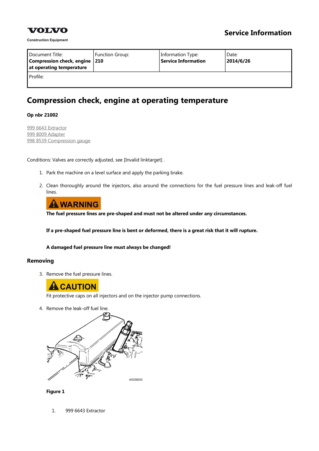
Service Information Document Title: Compression check, engine at operating temperature Function Group: 210 Information Type: Service Information Date: 2014/6/26 Profile: Compression check, engine at operating temperature Op nbr 21002 999 6643 Extractor 999 8009 Adapter 998 8539 Compression gauge Conditions: Valves are correctly adjusted, see [Invalid linktarget] . 1. Park the machine on a level surface and apply the parking brake. 2. Clean thoroughly around the injectors, also around the connections for the fuel pressure lines and leak-off fuel lines. WARNING The fuel pressure lines are pre-shaped and must not be altered under any circumstances. If a pre-shaped fuel pressure line is bent or deformed, there is a great risk that it will rupture. A damaged fuel pressure line must always be changed! Removing 3. Remove the fuel pressure lines. CAUTION Fit protective caps on all injectors and on the injector pump connections. 4. Remove the leak-off fuel line. Figure 1 1. 999 6643 Extractor
5. Remove the injector for cylinder no. 1. If necessary, use extractor 6643 to remove the injector. Make sure that the copper washer between the injector and the copper sleeve comes out. If it doesn t, use a wire hook to retrieve it. Figure 2 1. Copper washer 6. Fit adapter 8009 and fasten it using the injector yoke and nut. Tightening torque: 50 Nm (5.0 kpm) (37 lbf ft). 7. Connect compression gauge 8539. Figure 3 1. 2. 999 8009, Adapter 998 8539, Compression gauge 8. Pull out the stop button and secure the fuel injection pump stop control rod in the stop position. This is to prevent fuel from escaping from the pressure valves when the engine is turned over using the starter motor. 9. Check that the gearshift selector is in the neutral position. 10. Using the starter motor, turn over the engine for 5 seconds. 11. Remove the checking equipment and refit the injector, use a new copper washer. Tightening torque: 50 Nm (5.0 kpm) (37 lbf ft). 12. Perform a compression check on cylinders 2, 3, 4, 5 and 6 in the same manner as for cylinder 1. Remove the pipe between the turbo and the intercooler when checking cylinder no. 6.
Normal compression pressure is 2.6 MPa (26 bar) (377 psi) at 180 rpm. CAUTION A difference of up to 10% in compression between cylinders is fully acceptable and does not indicate a need for further action, such as reconditioning the valves. Mounting 13. Fit the leak-off fuel line, use new copper washers. 14. Refit the pipe between the turbo and the intercooler. WARNING The fuel pressure lines (delivery lines) are pre-shaped and must not be altered in any way under any circumstances. If a pre-shaped fuel pressure line is bent or deformed, there is a great risk that it will rupture. A damaged fuel pressure line must always be changed! 15. Fit the fuel pressure lines. Make sure that the area is clean and that the fuel pressure lines are not bent or altered in any way. Tighten the pressure line nuts. Tightening torque: 15 25 Nm (1.5 2.5 kpm) (11 18 lbf ft). 16. Restore the stop function. Start the engine and check that there are no leaks.
https://www.ebooklibonline.com Hello dear friend! Thank you very much for reading. Enter the link into your browser. The full manual is available for immediate download. https://www.ebooklibonline.com
Service Information Document Title: Description Function Group: 210 Information Type: Service Information Date: 2014/6/26 Profile: Description Articulated hauler A20C is fitted with a type TD73KFE engine. The engine is a straight six cylinder, direct-injected, turbocharged diesel engine with intercooler. The engine s type, part and serial numbers are punched into the left side of the engine block, under the turbocharger. For further information, see Section 0, Specifications. For repairs and service work on the engine, refer to separate Service Manual "Engine TD61/73, TD71/73".
Service Information Document Title: Engine and transmission, mounting Function Group: 210 Information Type: Service Information Date: 2014/6/26 Profile: Engine and transmission, mounting Op nbr 21074 Ratchet block 1 pc, 750 kg (1654 lbs) Torque wrench, 0 350 Nm (0 35 kpm) (0 258 lbf ft) Required lifting capacity: 1300 kg (2866 lbs) NOTE! If requisite lifting equipment is available, it is advantageous to lift the engine and transmission in and out of the machine as a single unit. WARNING There is a risk of scalding and burn injuries when opening the expansion tank cap (radiator cap) due to the high pressure in the cooling system. WARNING Hot oil and hot engine coolant can cause severe burns! WARNING Make sure that the engine hood torsion spring is relieved of any tension when removing the engine hood (engine hood in middle position). CAUTION Maintain greatest possible cleanliness when working on the hydraulic system. CAUTION If there has been a transmission breakdown or if there are impurities in the transmission oil sump, filter or oil system: change transmission oil cooler, see [Invalid linktarget] . thoroughly clean the lines to the transmission oil cooler. 1. Connect the lifting device to the engine lifting eyes. Lift the engine with transmission into the machine and lower it onto the engine mounts.
Figure 1 Lifting device with ratchet block at front of engine 2. Fit the centre bolts for the front engine mounts. Tightening torque: 185 Nm (18.5 kpm) (136 lbf ft). 3. Fit the bolts for the rear engine mounts. Tightening torque: 73 Nm (7.3 kpm) (54 lbf ft). 4. Fit the bolts for the propeller shaft. Tightening torque: 100 Nm (10 kpm) (74 lbf ft). To rotate the propeller shaft: Lift a wheel up on the front bogie axle and release the parking brake ("OFF" position). Charge the compressed air system through the filler valve with pressure hose E1514, [Invalid linktarget] . Figure 2 5. Fit the hydraulic pumps and new O-rings. Lock the bolts with locking compound ("medium"). 6. Fit the return hoses for the hydraulic pumps. 7. Connect the engine and transmission as follows: Fit the engine oil filters. See Operator s Manual, Changing oil filter. Connect the oil lines to the transmission. Fit the exhaust pipe, air induction hose for the turbo and the fuel lines. Connect the AC compressor (market adapted equipment) complete with bracket. Connect the hoses for the exhaust retarder, radiator, air compressor and heater. Connect the cables to sensors for engine speed, temperature, oil pressure and preheating relay. Connect cables to the frame grounding point and starter motor.
Fit the connector to the transmission. Figure 3 Connector X6/A4 on transmission 8. Fit the shut-off control for the hydraulic oil and open it. Figure 4 Shut-off control for hydraulic oil 1. 9. Fit the front member (approx. 20 kg (44 lbs)). Figure 5 Front member 10. Fasten the electric cabling to the front member. 11. Fill coolant in the expansion tank. Fill oil in the engine and transmission. 12. Fit the engine hood. Fit the lines and air connections. 13. Fit the cross members under the engine and transmission.
Fit the floor plate and operators seat. 14. Bleed air from the fuel system. Start the engine and check that there are no leaks. Check the coolant level and top up, if needed. 15. Fit the underbody skid plates 1, 2 and 3, see [Invalid linktarget] .
Service Information Document Title: Engine and transmission, removing Function Group: 210 Information Type: Service Information Date: 2014/6/26 Profile: Engine and transmission, removing Op nbr 21073 Ratchet block 1 pc, 750 kg (1654 lbs) Torque wrench, 0 350 Nm (0 35 kpm) (0 258 lbf ft) Required lifting capacity: 1300 kg (2866 lbs) NOTE! If requisite lifting equipment is available, it is advantageous to lift the engine and transmission in and out of the machine as a single unit. WARNING There is a risk of scalding and burn injuries when opening the expansion tank cap (radiator cap) due to the high pressure in the cooling system. WARNING Hot oil and hot engine coolant can cause severe burns! WARNING Make sure that the engine hood torsion spring is relieved of any tension when removing the engine hood (engine hood in middle position). CAUTION Maintain greatest possible cleanliness when working on the hydraulic system. CAUTION If there has been a transmission breakdown or if there are impurities in the transmission oil sump, filter or oil system: change transmission oil cooler, see [Invalid linktarget] . thoroughly clean the lines to the transmission oil cooler. 1. Cut the electric power with the battery disconnect switch. Drain the engine oil and the transmission oil.
Figure 1 Battery disconnect switch serial no. 3100 Figure 2 Battery disconnect switch serial no. 3101 2. Removing engine hood: Connect a lifting device to the engine hood. (Weight approx. 100 kg (220 lbs)). Open the hood to half open position so that the torsion spring is relieved of tension. Figure 3
Engine hood half open, torsion spring relieved of tension Remove the lines and air connections. Loosen the hinge halves and open them so that the hood can be removed from the torsion spring. Push back the hood until the torsion spring slides out of its bracket in the hood. Lift away the engine hood. Figure 4 Engine hood removed 3. Remove the underbody skid plates 1, 2 and 3 as well as the cross members under the engine and transmission. Figure 5 Underbody skid plates 4. Drain the coolant with the hose on the radiator. Open the valve on the rear left side of the engine block and the nipple on the pipe to the water pump. Figure 6 Draining coolant 1. Hose on radiator
Figure 7 Draining coolant 1. Valve on rear left side of engine block Figure 8 Draining coolant 1. Nipple on pipe to coolant pump Figure 9 Front member 5. Remove the electric cabling from the front member. 6. Remove the bolts and lift away the front member (approx. 20 kg (44 lbs)). 7. Remove the operator s seat and the front floor plate in the cab. 8. Turn off the shut-off valve for the hydraulic oil.
The control is located on the left fender. Figure 10 1. Shut-off control for hydraulic oil 9. Remove the stabilizer bar for the radiator. 10. Detach the engine and transmission as follows: CAUTION Make sure that the compressed air system is completely depressurized. Detach and swing out the radiator. Disconnect the connector from the transmission. Disconnect the ground cables from the frame grounding point and starter motor. Disconnect the cables for the engine speed sensor, temperature sensor, oil pressure sensor and preheating relay, R9. Disconnect the hoses for the exhaust retarder, radiator, air compressor and heater. Disconnect the AC compressor (market adapted equipment) complete with bracket. CAUTION Do not disconnect any AC hoses. Detach exhaust pipe, air induction hose for the turbo and fuel lines, and plug all connections. Disconnect the oil lines to the transmission and fit protective plugs. Remove the engine oil filters. Figure 11 Connector X6/A4 on transmission 11. Connect the lifting device to the engine lifting eyes. (Centre of gravity for the unit is approx. 150 mm (6 in) in front of the rear lifting eyes.)
Figure 12 Lifting device with ratchet block at front of engine 12. Remove the leak-oil hoses for the hydraulic pumps and plug the connections. 13. Remove the pumps from the power take-off, without disconnecting the hoses. A small amount of oil (approx. 0.5 litres (0.1 US gal)) will drain. Position the pumps so that the hoses are not deformed. Figure 13 Position of pumps 14. Remove the hydraulic oil shut-off control and secure the spool in its closed position, with a length of wire, for example. 15. Remove the centre bolts for the front engine mounts. 16. Loosen the rear engine mounts from the frame bracket. Remove the bolts, pos. 2.
Figure 14 Figure 15 1. Tensioning device 17. Disconnect the propeller shaft from the transmission drive flange and move the dropbox rearwards. To rotate the propeller shaft: Lift a wheel up on the front bogie axle and release the parking brake ("OFF" position). Charge the compressed air system through the filler valve with pressure hose E1514, [Invalid linktarget] . Figure 16 18. Lift up and pull the engine/transmission unit (approx. 1300 kg (2866 lbs)) forward so that the rear engine mounts and the power take-off for the pumps clear other machine parts. If needed, change the tilt of the engine/transmission unit using the ratchet block.
Figure 17 Lifting out engine and transmission 19. Lower the engine/transmission unit and support it securely.
Service Information Document Title: Engine, mounting Function Group: 210 Information Type: Service Information Date: 2014/6/26 Profile: Engine, mounting Op nbr 21072 Ratchet block 1 pc, 750 kg (1654 lbs) Torque wrench, 0 350 Nm (0 35 kpm) (0 258 lbf ft) Required lifting capacity: 1100 kg (2426 lbs) WARNING Hot oil and hot engine coolant can cause severe burns! WARNING Make sure that the engine hood torsion spring is relieved of any tension when removing the engine hood (engine hood in middle position). CAUTION Maintain greatest possible cleanliness when working on the hydraulic system. Figure 1 Lifting device with ratchet block at front of engine 1. Connect the lifting device to the engine lifting eyes. 2. Lift the engine into the machine and fit it against the transmission using the locating pins. 3. Fit the transmission retaining bolts. Tightening torque: 50 Nm (5 kpm) (37 lbf ft)
4. Rotate the torque converter using a ratchet handle in order to fit the first retaining bolt. Rotate the crankshaft by using: Ratchet handle with 3/4" drive Extension 3/4" Socket 13/16" 3/4" and fit the remaining bolts. Tightening torque: 80 Nm (8 kpm) (59 lbf ft) Figure 2 5. Remove the protective plate E1069 and fit the cover over the inspection hole in the flywheel housing and fit the plug. 6. Fit the hose bracket for the oil distributor with the hoses. Use new seals. 7. Fit the centre bolts for the front engine mounts. Tightening torque: 185 Nm (18.5 kpm) (136 lbf ft). 8. Fit the bolts for the rear engine mounts. Tightening torque: 73 Nm (7.3 kpm) (54 lbf ft). 9. Fit the hydraulic pumps, make sure to use new O-rings. Lock the bolts with locking compound ("medium"). 10. Fit the return hoses for the hydraulic pumps. Fit the engine oil filters. See Operator s Manual, Changing oil filter. Fit the exhaust pipe, air induction hose for the turbo and the fuel lines. Connect the AC compressor (market adapted equipment) complete with bracket. Connect the hoses for the exhaust retarder, radiator, air compressor and heater. Connect the cables to sensors for engine speed, temperature, oil pressure and preheating relay, R9. Connect cables to the frame grounding point and starter motor.
Figure 3 1. Shut-off control for hydraulic oil 11. Fit the shut-off control for the hydraulic oil and open it. 12. Fit the stabilizer bar for the radiator. Figure 4 Front member 13. Fit the front member (approx. 20 kg (44 lbs)). 14. Fasten the electric cabling to the front member. 15. Fill coolant in the expansion tank. Fill oil in the engine and transmission. 16. Fit the engine hood. 17. Fit the lines and air connections. 18. Fit the cross members under the engine and transmission. 19. Fit the floor plate and operator s seat. 20. Bleed air from the fuel system. Start the engine and check that there are no leaks. Check the coolant level and top up, if needed. 21. Fit the underbody skid plates 1, 2 and 3, see [Invalid linktarget] .
Service Information Document Title: Engine, removing Function Group: 210 Information Type: Service Information Date: 2014/6/26 Profile: Engine, removing Op nbr 21070 Ratchet block 1 pc, 750 kg (1654 lbs) Torque wrench, 0 350 Nm (0 35 kpm) (0 258 lbf ft) Required lifting capacity: 1100 kg (2426 lbs) WARNING Hot oil and hot engine coolant can cause severe burns! WARNING Make sure that the engine hood torsion spring is relieved of any tension when removing the engine hood (engine hood in middle position). CAUTION Maintain the greatest possible cleanliness when working on the hydraulic system. 1. Cut the electric power with the battery disconnect switch. Figure 1 Battery disconnect switch serial no. 3100,
Figure 2 Battery disconnect switch serial no. 3101 , 2. Removing engine hood: Connect a lifting device to the engine hood. (Weight approx. 100 kg (220 lbs)). Open the hood to half open position so that the torsion spring is relieved of tension. Figure 3 Engine hood half open, torsion spring relieved of tension Remove the lines and air connections. Loosen the hinge halves and open them so that the hood can be removed from the torsion spring. Push back the hood until the torsion spring slides out of its bracket in the hood.
Suggest: If the above button click is invalid. Please download this document first, and then click the above link to download the complete manual. Thank you so much for reading
Figure 4 Engine hood removed Lift away the engine hood. 3. Remove the underbody skid plates 1, 2 and 3, as well as the cross member under the engine. Figure 5 Underbody skid plates 4. Drain the engine oil. 5. Drain the coolant using the hose on the radiator. Figure 6 Draining coolant 1. Hose on radiator 6. Open the valve on the rear left side of the engine block.
https://www.ebooklibonline.com Hello dear friend! Thank you very much for reading. Enter the link into your browser. The full manual is available for immediate download. https://www.ebooklibonline.com


 (377 psi) at")