JCB VMD70 VMD100 Double Drum Walk Behind Roller Service Repair Manual Instant Download
Please open the website below to get the complete manualnn//

Download Presentation

Please find below an Image/Link to download the presentation.
The content on the website is provided AS IS for your information and personal use only. It may not be sold, licensed, or shared on other websites without obtaining consent from the author. Download presentation by click this link. If you encounter any issues during the download, it is possible that the publisher has removed the file from their server.
E N D
Presentation Transcript
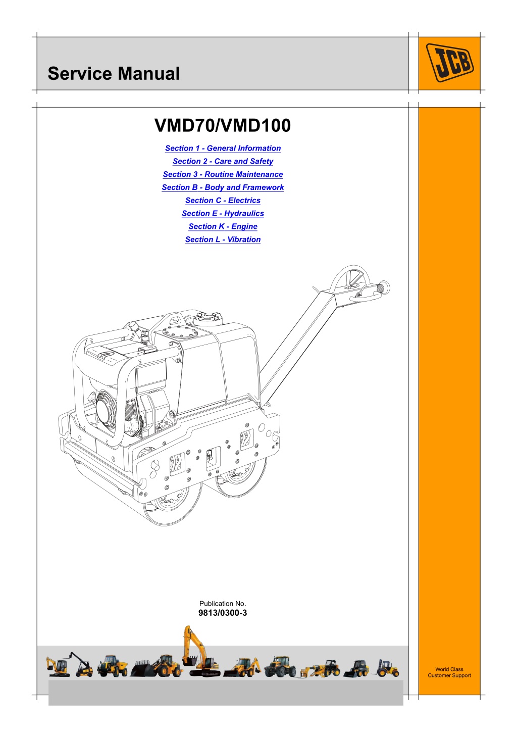
Service Manual VMD70/VMD100 Section 1 - General Information Section 2 - Care and Safety Section 3 - Routine Maintenance Section B - Body and Framework Section C - Electrics Section E - Hydraulics Section K - Engine Section L - Vibration Publication No. 9813/0300-3 World Class Customer Support Copyright 2004 JCB SERVICE. All rights reserved. No part of this publication may be reproduced, stored in a retrieval system, or transmitted in any form or by any other means, electronic, mechanical, photocopying or otherwise, without prior permission from JCB SERVICE. Issued by JCB Technical Publications, JCB Aftermarket Training, Woodseat, Rocester, Staffordshire, ST14 5BW, England. Tel +44 1889 591300 Fax +44 1889 591400
Section 1 - General Information Notes: 1-0 1-0 9813/0300-2
Section 1 - General Information Contents Introduction About This Manual ..................................................................................... 1-1 Machine Model and Serial Number .......................................................1-1 Using the Service Manual .....................................................................1-1 Section Numbering ................................................................................1-1 Left Side, Right Side ..............................................................................1-1 Cross References ..................................................................................1-2 Identifying Your Machine ........................................................................... 1-3 Machine Identification Plate ..................................................................1-3 Component Identification Plates ............................................................1-3 Page No. Service Tools Numerical List ............................................................................................ 1-5 Tool Detail Reference ................................................................................ 1-6 Section B - Body and Framework ..........................................................1-6 Section C - Electrics ..............................................................................1-8 Section E - Hydraulics ...........................................................................1-9 Section L - Vibration ............................................................................1-13 Torque Settings Zinc Plated Fasteners and Dacromet Fasteners ..................................... 1-15 Introduction ..........................................................................................1-15 Bolts and Screws .................................................................................1-15 Hydraulic Connections ............................................................................. 1-19 'O' Ring Face Seal System ..................................................................1-19 'Torque Stop' Hose System .................................................................1-22 Service Consumables Sealing and Retaining Compounds ......................................................... 1-23 1-i 1-i
Section 1 - General Information Contents Page No. 1-ii 1-ii
https://www.ebooklibonline.com Hello dear friend! Thank you very much for reading. Enter the link into your browser. The full manual is available for immediate download. https://www.ebooklibonline.com
Section 1 - General Information Introduction About This Manual Machine Model and Serial Number Finally, please remember above all else safety must come first! This manual provides information for the following model(s) in the JCB machine range: Section Numbering T11-005 VMD70/100 from SN 1601000 to 1601999 and 2703000 to 2704999. The manual is compiled in sections, the first three are numbered and contain information as follows: Using the Service Manual General Information - includes torque settings and service tools. Care and Safety - includes warnings and cautions pertinent to aspects of workshop procedures etc. Maintenance - includes service schedules and recommended lubricants for all the machine. 1 T11-004 This publication is designed for the benefit of JCB Distributor Service Engineers who are receiving, or have received, training by JCB Technical Training Department. 2 3 These personnel should have a sound knowledge of workshop practice, safety procedures, and general techniques associated with the maintenance and repair of hydraulic earthmoving equipment. The remaining sections are alphabetically coded and deal with Dismantling, Overhaul etc. of specific components, for example: The illustrations in this publication are for guidance only. Where the machines differ, the text and/or the illustration will specify. Attachments Body and Framework, etc. A B General warnings in Section 2 are repeated throughout the manual, as well as specific warnings. Read all safety statements regularly, so you do not forget them. Section contents, technical data, circuit descriptions, operation descriptions etc. are inserted at the beginning of each alphabetically coded section. Renewal of oil seals, gaskets, etc., and any component showing obvious signs of wear or damage is expected as a matter of course. It is expected that components will be cleaned and lubricated where appropriate, and that any opened hose or pipe connections will be blanked to prevent excessive loss of hydraulic fluid and ingress of dirt. Left Side, Right Side In this manual, 'left' A and 'right' B mean your left and right when you stand correctly behind the machine and face forwards. Where a torque setting is given as a single figure it may be varied by plus or minus 3%. Torque figures indicated are for dry threads, hence for lubricated threads may be reduced by one third. The manufacturer's policy is one of continuous improvement. The right to change the specification of the machine without notice is reserved. No responsibility will be accepted for discrepancies which may occur between specifications of the machine and the descriptions contained in this publication. 1-1 1-1 9813/0300-2
Section 1 - General Information Introduction About This Manual Cross References T1-004_2 In this publication, page cross references are made by presenting the subject title printed in bold, italic and underlined. It is preceeded by the 'go to' symbol. The number of the page upon which the subject begins, is indicated within the brackets. For example: K K Cross References ( T T 1-2). 1-2 1-2 9813/0300-2
Section 1 - General Information Introduction Identifying Your Machine Identifying Your Machine Machine Identification Plate Typical Product Identification Number (PIN) Your machine has an identification plate mounted as shown. K K Fig 1. ( T T 1-3). 1 2 3 C 4 JCB VMD 02802400 The machine and engine serial numbers can help identify exactly the type of equipment you have. World Manufacturer Code (JCB) 1 Machine Type and Model 2 Randomly Generated Check Letter 3 JCB VIBROMAX GmbH SCHAEFERBERG 1 06466 GATERSLEBEN Machine Serial Number (02802400) 4 Component Identification Plates Product Identification Number, PIN, ISO 10261 YEAR OF MANUFACTURE TYPE Engine Identification Plate MAX FRONT AXLE LOAD (kg) MAX REAR AXLE LOAD (kg) OPERATING MASS (kg) EN500-1 ENGINE POWER kW @ RPM, ISO 3046-1 332/N0674 The engine serial number is located on the engine crankcase next to the dipstick. T052960-2 Fig 1. 1-3 1-3 9813/0300-2
Section 1 - General Information Introduction Identifying Your Machine Page left intentionally blank 1-4 1-4 9813/0300-2
Section 1 - General Information Service Tools Numerical List The tools listed in the table are special tools required for carrying out the procedures described in this manual. These tools are available from JCB Service. details of all tools, including the content of kits and sets, refer to Tool Detail Reference, Section 1. Note: Tools other than those listed will be required. It is expected that such general tools will be available in any well equipped workshop or be available locally from any good tool supplier. Some tools are available as kits or sets, the part numbers for parts within such kits or sets are not listed here. For full Part Number - - - - - - Description See Section Bonded Washers - see Tool Detail Reference (Section 1) for content Female Cone Blanking Caps - see Tool Detail Reference (Section 1) for content Female Connectors - see Tool Detail Reference (Section 1) for content Hydraulic Flow Test Equipment - see Tool Detail Reference (Section 1) for content Male Adapters - BSP x BSP - see Tool Detail Reference (Section 1) for content Male Adapters - BSP x NPT (USA only) - see Tool Detail Reference (Section 1) for content Male Cone Blanking Caps - see Tool Detail Reference (Section 1) for content Pressure Test Points - Adaptors - see Tool Detail Reference (Section 1) for content Pressure Test Points - 'T' Adaptors - see Tool Detail Reference (Section 1) for content Rivet Nut Tool - see Tool Detail Reference (Section 1) for content Hand Cleaner Hydraulic Circuit Pressure Test Kit - see Tool Detail Reference (Section 1) for content Hose Gauge Gauge Digital Tachometer Hyd. Oil Temperature Probe Fluke Meter Gauge E E E E E E - - - - 4104/1310 892/00253 892/00254 892/00279 892/00280 892/00284 892/00285 892/00298 892/00346 E E E B B E E E E C C C E E E E E B C 892/00347 892/01246 892/01247 892/12345 993/68100 892/00285 Connector Vibromax male to JCB female threaded adaptor JCB male to Vibromax female threaded adaptor Frequency and Vibration Measuring Tool Slide Hammer Kit - see Tool Detail Reference (Section 1) for content 100 amp Shunt 1-5 1-5 9813/0300-2
Section 1 - General Information Service Tools Tool Detail Reference Tool Detail Reference Section B - Body and Framework Note: Not all service tools are illustrated. Fig 1. 993/68100 Slide Hammer Kit 993/68101 993/68102 993/68103 993/68104 993/68105 993/68106 Slide Hammer End Stops Adaptor - M20 x 5/8" UNF Adaptor - M20 x 1" UNF Adaptor - M20 x M20 Adaptor - M20 x M24 993/68107 993/68108 993/68109 993/68110 993/68111 Bar - M20 x M20 X 800 mm Adaptor - M20 x 7/8" UNF Adaptor - M20 x M12 Adaptor - M20 x 5/8" UNF (Shoulder) Adaptor - M20 x 1/2" UNF 1 2 3 4 5 6 7 8 9 10 11 826/01099 826/01101 826/01102 826/01103 826/01104 826/01105A - M6 x 16 mm Rivet Nut M6 x 19 mm Rivet Nut M8 x 18 mm Rivet Nut M8 x 21 mm Rivet Nut M10 x 23 mm Rivet Nut M10 x 26 mm Rivet Nut Installation Tool available from: Bollhoff Fastenings Ltd (www.bollhof.com) 1 2 Fig 2. Rivet Nut Tool 1-6 1-6 9813/0300-2
Section 1 - General Information Service Tools Tool Detail Reference Fig 3. 4104/1310 Hand Cleaner Special blend for the removal of polyurethane adhesives (454g; 1 lb tub). 1-7 1-7 9813/0300-2
Section 1 - General Information Service Tools Tool Detail Reference Section C - Electrics Note: Not all service tools are illustrated. Fig 4. 892/00298 Fluke Meter Fig 5. 892/00285 Hydraulic Temperature Probe Fig 6. 892/00284 Venture Microtach Digital Tachometer 1-8 1-8 9813/0300-2
Section 1 - General Information Service Tools Tool Detail Reference Section E - Hydraulics Note: Not all service tools are illustrated. Male Adapters - BSP x BSP 3/8 in. x 1/4 in. 3/8 in. x 3/8 in. 3/8 in. x 3/8 in. taper 1/2 in. x 1/4 in. 1/2 in. x 3/8 in. 1/2 in. x 1/2 in. 5/8 in. x 1/2 in. 3/4 in. x 3/8 in. 3/4 in. x 1/2 in. 3/4 in. x 3/4 in. 3/4 in. x 1 in. 3/4 in. x 1.1/4 in. 1 in. x 1.1/4 in. 1606/2052 1604/0003A 892/00071 1606/0004 1606/0007A 1604/0004A 1606/0017 1606/0008 1606/0009 1604/2055 1606/0012 1606/0014 1606/0015 Fig 7. Male Adaptors Male Adapters - BSP x NPT (USA only) 3/8 in. x 1/4 in. 1/2 in. x 1/4 in. 3/8 in. x 3/8 in. 1/2 in. x 3/8 in. 816/00439 816/00440 816/15007A 816/15008 892/00255 892/00256 892/00257 892/00258 816/15118 892/00259 892/00260 892/00261 1/4 in. BSP x Test Point 3/8 in. BSP x Test Point 1/2 in. BSP x Test Point 5/8 in. BSP x Test Point 3/4 in. BSP x Test Point 1 in BSP x Test Point 1.1/4 in. BSP x Test Point 5/8 in. UNF x Test Point Fig 8. Pressure Test Adapters 816/55045 816/55038 816/55040 892/00263 892/00264 1/4 in. M BSP x 1/4 in. F BSP x Test Point 3/8 in. M BSP x 3/8 in. F BSP x Test Point 1/2 in. M BSP x 1/2 in. F BSP x Test Point 5/8 in. M BSP x 5/8 in. F BSP x Test Point 3/4 in. M BSP x 3/4 in. F BSP x Test Point 892/00265 892/00266 892/00267 1 in. M BSP x 1 in. F BSP x Test Point 1.1/4 in. M BSP x 1.1/4 in. F BSP x Test Point 1.1/4 in. M BSP x 1.1/2 in. F BSP x Test Point Fig 9. Pressure Test 'T' Adapters 1-9 1-9 9813/0300-2
Section 1 - General Information Service Tools Tool Detail Reference 892/00047 892/00048 892/00049 816/50043 892/00051 816/50005 816/60096 816/00017 3/8 in. BSP (A) x 1/4 in. BSP (B) 1/2 in. BSP (A) x 1/4 in. BSP (B) 5/8 in. BSP (A) x 1/4 in. BSP (B) 3/4 in. BSP (A) x 1/4 in. BSP (B) 1 in. BSP (A) x 1/4 in. BSP (B) 1/2 in. BSP (A) x 1/2 in. BSP (B) 3/4 in. BSP (A) x 3/4 in. BSP (B) 1 in. BSP (A) x 1 in. BSP (B) Fig 10. 'T' Adapters 892/00055A 892/00056A 892/00057 892/00058A 892/00059A 892/00060 1/4 in. BSP 3/8 in. BSP 1/2 in. BSP 5/8 in. BSP 3/4 in. BSP 1 in. BSP Fig 11. Female Blanking Caps 816/90045 816/00189A 816/00190A 816/90022 816/90274 816/90205 1/4 in. BSP 3/8 in. BSP 1/2 in. BSP 5/8 in. BSP 3/4 in. BSP 1 in. BSP Fig 12. Male Cone Blanking Caps 892/00074 892/00075 892/00076 892/00077 3/8 in. BSP x 3/8 in. BSP 1/2 in. BSP x 1/2 in. BSP 5/8 in. BSP x 5/8 in. BSP 3/4 in. BSP x 3/4 in. BSP Fig 13. Female Connectors 1406/0011 1406/0018 1406/0014 1406/0021 1406/0029 1/4 in. BSP 1/2 in. BSP 5/8 in. BSP 3/4 in. BSP 1.1/4 in. BSP Fig 14. Bonded Washers 1-10 1-10 9813/0300-2
Section 1 - General Information Service Tools Tool Detail Reference 892/00268 892/00269 892/00273 892/00293 892/00270 1406/0021 1604/0006A 1612/2054 892/00271 892/00272 816/20008 892/00275 892/00276 892/00277 1606/0015 892/00078 1604/0008 1604/0008 816/20013 Flow Monitoring Unit Sensor Head 0 - 100 l/min (0 - 22 UK gal/min) Sensor Head 0 - 380 l/min (0 - 85.5 UK gal/min) Connector Pipe Load Valve Bonded Washer Adapter 3/4 in M x 3/4 in M BSP Adapter 3/4 in F x 3/4 in M BSP Adapter 3/4 in F x 5/8 in M BSP Adapter 5/8 in F x 3/4 in M BSP Adapter 3/4 in F x 1/2 in M BSP Adapter 1/2 in F x 3/4 in M BSP Adapter 3/4 in F x 3/8 in M BSP Adapter 3/8 in F x 3/4 in M BSP Adapter 1.1/4 in M BSP x 1 in M BSP Connector 1 in F x 1 in F BSP Adapter 1 in M x 1 in M BSP Adapter 1 in M x 3/4 in M BSP Adapter 3/4 in F x 1 in M BSP Fig 15. Flow Test Equipment 892/00201 Replacement Gauge 0-20 bar (0-300 lbf/in2) 892/00202 Replacement Gauge 0-40 bar (0-600 lbf/in2) 1 892/00203 Replacement Gauge 0-400 bar (0-6000 lbf/in2) Replacement Hose Seal Kit for 892/00254 (can also be used with probe 892/00706) Test Probe Connector - Hose to gauge 2 3 892/00254 993/69800 892/00706 892/00347 Fig 16. 892/ 00253 Hydraulic Circuit Pressure Test Kit 1-11 1-11 9813/0300-2
Suggest: If the above button click is invalid. Please download this document first, and then click the above link to download the complete manual. Thank you so much for reading
Section 1 - General Information Service Tools Tool Detail Reference 892/00280 Pressure Gauge 0-600 bar (0-9000 lbf/in2) 892/00279 Pressure Gauge 0-400 bar (0-6000 lbf/in2) 892/00346 Pressure Gauge 0-70 bar (0-1000 lbf/in2) Connector Hose 892/00347 892/00254 Fig 17. Hydraulic Circuit Test Gauges and Connections Fig 18. Adaptor (item A) Fig 19. 892/12345 Frequency and Vibration Measuring Tool Allows the service engineer to measure the frequency of the vibrating drum (it will also measure engine speed on any type of machinery). Item A Part No 892/01247 JCB male to Vibromax female threaded adaptor - Connects JCB female test hose to male Vibromax test point 892/01246 Vibromax male to JCB female threaded adaptor - Connects Vibromax female test hose to JCB male test point Description Qty a/r B a/r Note: In order to use JCB test hoses and gauges on JCB Vibromax machines (and where applicable, other manufacturers machines fitted with M16 X2mm test points) a special adaptor A is required. For JCB Vibromax dealers or customers that already have JCB Vibromax compatible test hoses a `special adaptor' B (not shown) will be required to connect to JCB test points 1-12 1-12 9813/0300-2
Section 1 - General Information Service Tools Tool Detail Reference Section L - Vibration 332/N3174 Vibration Shaft Bearing Pull. 1-13 1-13 9813/0300-2
https://www.ebooklibonline.com Hello dear friend! Thank you very much for reading. Enter the link into your browser. The full manual is available for immediate download. https://www.ebooklibonline.com