JCB VIBROMAX VM116 VM146 VM166 VM186 Single Drum Roller Service Repair Manual Instant Download
Please open the website below to get the complete manualnn//

Download Presentation

Please find below an Image/Link to download the presentation.
The content on the website is provided AS IS for your information and personal use only. It may not be sold, licensed, or shared on other websites without obtaining consent from the author. Download presentation by click this link. If you encounter any issues during the download, it is possible that the publisher has removed the file from their server.
E N D
Presentation Transcript
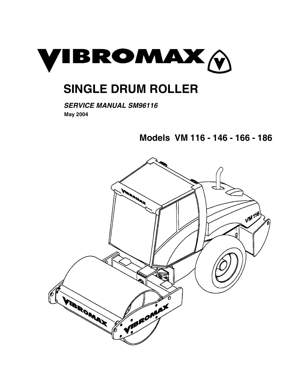
SINGLE DRUM ROLLER SERVICE MANUAL SM96116 May 2004 Models VM 116 - 146 - 166 - 186
CALIFORNIA Proposition 65 Warning Diesel engine exhaust and some of its constituents are known to the State of California to cause cancer, birth defects, and other reproductive harm.
SECTION ONE GENERAL INFORMATION MACHINE DESCRIPTION...............................................................................1 - 3 SERIAL NUMBERS............................................................................... 1 - 5 IDENTIFYING MACHINE COMPONENTS........................................... 1 - 6 FLUID SPECIFICATIONS................................................................................1 - 7 MACHINE SPECIFICATIONS..........................................................................1 - 8 MODEL VM116 ..................................................................................... 1 - 8 MODEL VM146 ...................................................................................1 - 10 MODEL VM166 ...................................................................................1 - 12 MODEL VM186 ...................................................................................1 - 14 STANDARD TORQUE DATA.............................................................. 1 - 16 DIESEL FUEL SPECIFICATION......................................................... 1 - 18 ENGINE OIL SPECIFICATION......................................................................1 - 19 SAFETY, GENERAL......................................................................................1 - 20 SPARK ARRESTER ......................................................................................1 - 20 PERSONAL....................................................................................................1 - 21 MACHINE OPERATION ................................................................................1 - 22 MAINTENANCE.............................................................................................1 - 25 MAINTENANCE SCHEDULE ........................................................................1 - 29 SECTION TWO ENGINE CUMMINS ENGINE WARRANTY....................................................................2 - 2 SECTION THREE ELECTRICAL GENERAL INFORMATION..............................................................................3 - 3 FUSES.............................................................................................................3 - 4 RELAYS...........................................................................................................3 - 5 INSTRUMENT PANEL.....................................................................................3 - 6 UNDERSTANDING ELECTRICAL SCHEMATICS........................................3 - 11 UNDERSTANDING RELAYS.........................................................................3 - 14 STARTER/CHARGING CIRCUIT ..................................................................3 - 17 EMERGENCY STOP.....................................................................................3 - 17 UNDERSTANDING BATTERIES...................................................................3 - 17 UNDERSTANDING ALTERNATORS............................................................3 - 19 UNDERSTANDING STARTERS....................................................................3 - 22 INSTRUMENTATION PANEL........................................................................3 - 27 1
BRAKE SWITCH............................................................................................3 - 29 HIGH SPEED CIRCUIT .................................................................................3 - 31 VIBRATION CIRCUIT....................................................................................3 - 33 ROAD LIGHTING CIRCUIT...........................................................................3 - 35 WORK LIGHTS & ACCESSORY PLUG........................................................3 - 37 CAB CIRCUITS..............................................................................................3 - 39 ELECTRICAL SCHEMATICS ........................................................................3 - 40 PLUG CONNECTORS...................................................................................3 - 48 INSTRUMENT HARNESS 7242/80435.........................................................3 - 49 WIRE CHART 7242/80435 ............................................................................3 - 51 RELAY/FUSE HARNESS 7242/80415 ..........................................................3 - 54 WIRE CHART 7242/80415 ............................................................................3 - 56 REAR HARNESS 7242/80510.......................................................................3 - 60 WIRE CHART 7242/80510 ............................................................................3 - 62 SECTION FOUR HYDRAULIC HYDRAULIC COOLING SYSTEM...................................................................4 - 2 HYDRAULIC DRAIN LINES.............................................................................4 - 4 HYDRAULIC TEST SYSTEM ..........................................................................4 - 6 HYDRAULIC TEST STATION..........................................................................4 - 7 CHARGE SYSTEM..........................................................................................4 - 9 PROPULSION SYSTEM................................................................................4 - 11 MULTIFUNCTION VALVES...........................................................................4 - 15 PROPULSION SYSTEM DIAGNOSTICS......................................................4 - 16 PUMP SERVO CONTROL.............................................................................4 - 17 VIBRATION SYSTEM....................................................................................4 - 19 VIBRATION FREQUENCY............................................................................4 - 21 VIBRATION AMPLITUDE..............................................................................4 - 23 VIBRATORY SYSTEM DIAGNOSTICS.........................................................4 - 24 STEERING SYSTEM.....................................................................................4 - 25 PARKING BRAKE SYSTEM..........................................................................4 - 28 TOWING YOUR MACHINE ...........................................................................4 - 29 TOWING PROCEDURE...................................................................... 4 - 30 PARKING BRAKE DIAGNOSTICS................................................................4 - 30 HOOD LIFT SYSTEM ....................................................................................4 - 33 HYDRAULIC COMPONENTS........................................................................4 - 36 HYDRAULIC SCHEMATIC............................................................................4 - 37 2
https://www.ebooklibonline.com Hello dear friend! Thank you very much for reading. Enter the link into your browser. The full manual is available for immediate download. https://www.ebooklibonline.com
SECTION FIVE POWER TRAIN DRUM REMOVAL............................................................................................5 - 2 DRUM INSTALLATION....................................................................................5 - 2 DRUM DRIVE ..................................................................................................5 - 3 DRUM DRIVE BEARING REMOVAL...............................................................5 - 5 DRUM DRIVE BEARING INSTALLATION.......................................................5 - 7 DRUM DRIVE MOTOR REPAIRS ...................................................................5 - 9 DRUM DRIVE GEARBOX................................................................................5 - 9 GFT 17 T2/312 2 GEARBOX.........................................................................5 - 11 GFT 36 T3 1042 GEARBOX..........................................................................5 - 13 SECTION SIX PARKING BRAKE SYSTEM DESCRIPTION.................................................................................................6 - 2 BRAKE RELEASE AND TOWING...................................................................6 - 3 TOWING PROCEDURE ..................................................................................6 - 4 SECTION SEVEN VIBRATION SYSTEM VIBRATION SYSTEM......................................................................................7 - 2 VIBRATION FREQUENCY..............................................................................7 - 3 VIBRATION AMPLITUDE................................................................................7 - 5 VIBRATORY SYSTEM DIAGNOSTICS...........................................................7 - 6 LIFTING DEVICE.............................................................................................7 - 7 DRUM REMOVAL............................................................................................7 - 8 DRUM INSTALLATION....................................................................................7 - 8 EXCITER BEARING REMOVAL......................................................................7 - 9 EXCITER BEARING ASSEMBLY..................................................................7 - 13 DRUM EXCITER SHAFT...............................................................................7 - 14 3
SECTION EIGHT STEERING SYSTEM SPECIAL TOOLS.............................................................................................8 - 2 ARTICULATION JOINTS.................................................................................8 - 3 JOINT DISASSEMBLY ....................................................................................8 - 5 JOINT ASSEMBLY ..........................................................................................8 - 9 SECTION NINE CHASSIS SECTION TEN ATTACHMENTS ROLL OVER PROTECTION STRUCTURE (ROPS) .....................................10 - 2 ROPS TIGHTENING TORQUES ........................................................10 - 2 4
SECTION ONE GENERAL INFORMATION May 2004 1 - 1
1 - 2 May 2004
SM96116 - SECTION ONE GENERAL INFORMATION MACHINE DESCRIPTION This book introduces the new Vibromax 6 series single drum rollers. Included within the pag- es of the book are materials covering the Models VM116, VM146, VM166, and VM186. The new rollers all use the Cummins 5.9 liter 6 cylinder en- gine. The engines are turbo- charged with cooling. All of the new engines are tuned to meet the latest EPA emissions standards. charge air A Sauer Sundstrand Series 90 variable displacement, axial piston hydrostatic pump, used for machine propulsion, is mounted to the flywheel end of the engine. It provides oil to a 2 speed drum drive motor and a 2 speed axle drive motor in a parallel path. The drum motor is mounted on the left side of the drum and drives through a planetary gearbox and is isolat- ed from the drum by rubber buffers. The axle drive motor is attached directly to the rear axle which is a no-spin design. May 2004 1 - 3
SM96116 - SECTION ONE GENERAL INFORMATION The vibration system uses a Sauer Sund- strand Series 90 hydrostatic pump similar to the propulsion pump and mounted directly behind the propulsion pump. The vibratory pump supplies oil to a Series 90 hydrostatic motor mounted at the right side of the drum. The new models operate at frequencies of 1740 or 2160 vibrations per minute on both the smooth drum and pad foot versions. These machines come standard with park- ing brakes at both the front drum and the rear axle. A spring applied-hydraulically re- leased multi disc brake is part of the drum drive motor gearbox. The axle uses a spring applied hydraulically released multiple disc brake at each axle shaft. Pressure testing has been made easier by placing all the test ports at a centrally locat- ed test station under the engine hood on the right side of the machine. A steering pump, mounted to the rear of the vibration pump, provides the oil needed for steering. The steering pump is also a sec- ond charge pump in the propulsion/vibra- tion circuit. The steering pump draws oil from the reservoir, passes it through the steering control valve, through the inline hy- draulic filter, and into the charge circuit. The charge pump draws oil from the reser- voir, joins the steering oil at the filter, pass- es it through the filter and into the charge circuit. The electrical system consists of a 12 volt battery, starter, alternator system, optional lighting and standard instrumentation and back-up alarm. The machines come standard with ROPS and seat belt. An optional ROPS cab is available. Check with your Vibromax dealer for other available options. 1 - 4 May 2004
SM96116 - SECTION ONE GENERAL INFORMATION SERIAL NUMBERS 1 2 3 4 5 6 7 8 Model / Serial Number Front Drum Drive Motor S/N Steering Unit S/N Axle S/N Vibratory Motor S/N Hydraulic Pumps S/N Axle Drive Motor S/N Engine S/N May 2004 1 - 5
SM96116 - SECTION ONE GENERAL INFORMATION IDENTIFYING MACHINE COMPONENTS 1 Articulation joint 2 Smooth drum 3 Lifting and towing eyes 4 Operator s platform 5 6 Hydraulic tank 7 8 9 10 Drum drive motor 11 12 13 14 15 16 17 18 19 Isolation buffer Scraper Engine exhaust Fuel tank Cooling system Vibration motor Steering cylinder Hydraulic pumps Axle drive motor Battery Engine Axle Air filter 1 - 6 May 2004
SM96116 - SECTION ONE GENERAL INFORMATION FLUID SPECIFICATIONS CAPACITY USA (metric) MACHINE PART SPECIFICATIONS Fuel tank 105 gal (397 ltr) see diesel fuel Engine crankcase 15 qts(14.5 ltr) engine oil API classification API CI-4 multigrade engine oil (see oil chart) VM116, VM146 VM166, VM186 Hydraulic system 21.1 gal (80 ltr) cold weather HLP 46 DIN 51524/2 hot weather HLP 68 DIN 51524/2 Mobil DTE 25,26 Shell Tellus OL 46,68 Amoco Rykon HD 46,68 Texaco Rando HD 46,68 Reservoir only 14.5 gal (55 ltr) Vibration system 12.7 qts. (12 ltr) CLP 150 DIN 51517/3 Mobil Gear 629 Shell Omala 150 Texaco Meropa 150 Battery as required Distilled water Grease as required KP3K DIN 51502 Mobil Oil - Mobilux 3 Shell Oil - Alvania 3 Texaco Oil - Starplex 3 Engine coolant 20 qts (19 ltr) 50% ethylene glycol and 50% water Tire ballast see chart Calcium Chloride (77%CaCl2 ) ZF Axle gear 15.8 qts. (15 ltr) SAE 90 API GL-5 gear lubricant alternate SAE85/140 API GL-5 gear lubricant Drum gearbox VM116 VM146 & VM166 CLP 220 LS 2 DIN 51517/3 Mobilgear 630 Mobilgear SHC 220 Texaco Syngear 220 1.4 qts (1.3 l) VM186 3.8 qts (3.6 l) May 2004 1 - 7
SM96116 - SECTION ONE GENERAL INFORMATION MACHINE SPECIFICATIONS MODEL VM116 in. mm a b c d1 d2 d3 d4 h h1 k l o s w e1 e2 118.0 89.4 65.0 59.8 59.1 55.1 63.0 115.6 85.0 17.6 225.3 3.3 1.0 82.7 41 degrees 29 degrees 2996 2270 1651 1520 1500 1400 1600 2935 2160 447 5722 85 25 2100 1 - 8 May 2004
SM96116 - SECTION ONE GENERAL INFORMATION ENGINE Make/Model/Type/Displacement - cu. in. (cc) Cummins 5.9 150C, 6 cylinder turbo diesel (water cooled), 359 cu.in. (5880cc) with charge air cooler 150 (112) Dual replaceable elements, Spin-on cartridge 105.7 (400) VM116D HP, SAE net (kW) @2200 rpm Air Cleaner / Fuel filter Fuel capacity - gal (ltr) VM116PD Operating weight max. -lb (kg) 28860 (13000) 29542 (13400) Weight, front-lb (kg) 16094 (7300) 16976 (7700) Weight, rear axle - lb (kg) 12566 (5700) 12566 (5700) Static applied linear drum load lb/in (kg/cm) 195 (34.8) ----------- Articulation/oscillation-degrees 35/15 35/15 Turning radius-inside-in. (m) 142 (3.6) 142 (3.6) Drum shell thickness-in. (mm) 1.0 (25) 1.0 (25) Number of pad feet/height of foot - in. (mm) 132/ 3.9 (100) Contact area of foot-sq. in. (cm) 64 sq.in.(413 sq. cm) Tire size 23.1 - 26 8PR diamond tread 23.1 - 26 8PR tractor tread Travel speed - 1st range mph (km/hr) 0 - 4.8 (0 - 7.7) 0 - 4.8 (0 - 7.7) - 2nd range mph (km/hr) 0 - 7.9 (0 - 12.7) 0 - 7.9 (0 - 12.7) Theoretical gradeability up to - % 60 65 Brakes - front drum disc disc - rear axle disc - input shaft disc - input shaft 1st Stage 2nd Stage 1st Stage 2nd Stage Max compaction depth up to - in. (cm) 39 (100) 31 (80) 39 (100) 31 (80) Frequency - vpm (Hz) 1740 (29) 2160 (36) 1740 (29) 2160 (36) Amplitude - in. (mm) .079 (2.0) .031 (0.8) .079 (2.0) .031 (0.8) Centrifugal force - lbf (kN) 63396 (282) 39117 (174) 68567 (305) 42264 (188) Centrifugal force/drum width - lb/in. (N/cm) 767 (1343) 473 (829) 829 (1452) 511 (895) May 2004 1 - 9
Suggest: If the above button click is invalid. Please download this document first, and then click the above link to download the complete manual. Thank you so much for reading
SM96116 - SECTION ONE GENERAL INFORMATION MODEL VM146 in. mm a b c d1 d2 d3 d4 h h1 k l o s w e1 e2 118.0 89.4 65.0 59.8 59.1 55.1 63.0 115.6 85.0 17.6 225.3 3.3 1.4 82.7 41 degrees 29 degrees 2996 2270 1651 1520 1500 1400 1600 2935 2160 447 5722 85 35 2100 1 - 10 May 2004
SM96116 - SECTION ONE GENERAL INFORMATION ENGINE Make/Model/Type/Displacement - cu. in. (cc) Cummins 5.9 173C, 6 cylinder turbo diesel (water cooled), 359 cu.in. (5880cc) with charge air cooler 173 (129) Dual replaceable elements, Spin-on cartridge 105.7 (400) VM146D HP, SAE net (kW) @2200 rpm Air Cleaner / Fuel filter Fuel capacity - gal (ltr) VM146PD Operating weight max. -lb (kg) 31306 (14200) 32187 (14600) Weight, front-lb (kg) 15873 (7200) 16775 (7600) Weight, rear axle - lb (kg) 15432 (7000) 15432 (7000) Static applied linear drum load lb/in (kg/cm) 192 (34.3) ----------- Articulation/oscillation-degrees 35/15 35/15 Turning radius-inside-in. (m) 142 (3.6) 142 (3.6) Drum shell thickness-in. (mm) 1.4 (35) 1.4 (35) Number of pad feet/height of foot - in. (mm) 132/ 3.9 (100) Contact area of foot-sq. in. (cm) 64 sq.in.(413 sq. cm) Tire size 23.1 - 26 8PR diamond tread 23.1 - 26 8PR tractor tread Travel speed - 1st range mph (km/hr) 0 - 4.5 (0 - 7.3) 0 - 4.5 (0 - 7.3) - 2nd range mph (km/hr) 0 - 7.1 (0 - 11.4) 0 - 7.1 (0 - 11.4) Theoretical gradeability up to - % 62 65 Brakes - front drum disc disc - rear axle disc - input shaft disc - input shaft 1st Stage 2nd Stage 1st Stage 2nd Stage Max compaction depth up to - in. (cm) 47 (120) 39 (100) 47 (120) 39 (100) Frequency - vpm (Hz) 1740 (29) 2100 (35) 1740 (29) 2100 (35) Amplitude - in. (mm) .071 (1.8) .031 (0.8) .071 (1.8) .031 (0.8) Centrifugal force - lbf (kN) 66768 (297) 43163 (192) 66768 (297) 43163 (192) Centrifugal force/drum width - lb/in. (N/cm) 808 (1414) 522 (914) 808 (1414) 522 (914) May 2004 1 - 11
https://www.ebooklibonline.com Hello dear friend! Thank you very much for reading. Enter the link into your browser. The full manual is available for immediate download. https://www.ebooklibonline.com