JCB VIBROMAX 405 605 606 SINGLE DRUM ROLLER Service Repair Manual Instant Download
Please open the website below to get the complete manualnn//

Download Presentation

Please find below an Image/Link to download the presentation.
The content on the website is provided AS IS for your information and personal use only. It may not be sold, licensed, or shared on other websites without obtaining consent from the author. Download presentation by click this link. If you encounter any issues during the download, it is possible that the publisher has removed the file from their server.
E N D
Presentation Transcript
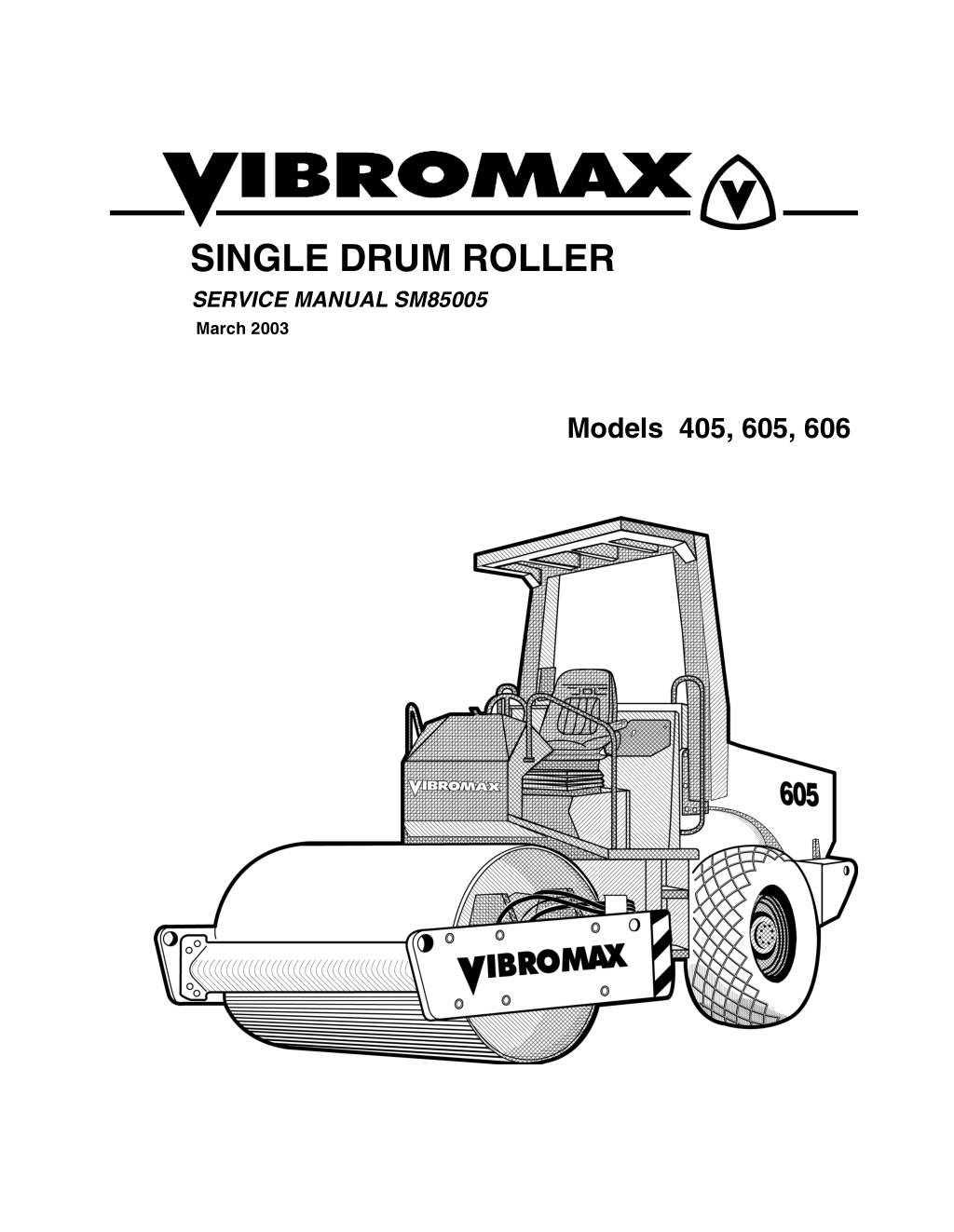
SINGLE DRUM ROLLER SERVICE MANUAL SM85005 March 2003 Models 405, 605, 606
CALIFORNIA Proposition 65 Warning Diesel engine exhaust and some of its constituents are known to the State of California to cause cancer, birth defects, and other reproductive harm.
table of contents SECTION ONE GENERAL INFORMATION ..............................................................1 - 1 MACHINE DESCRIPTION.............................................................................. 1 - 3 SERIAL NUMBERS ........................................................................................ 1 - 5 IDENTIFYING MACHINE COMPONENTS ..................................................... 1 - 6 FLUID SPECIFICATIONS - 405 ...................................................................... 1 - 8 FLUID SPECIFICATIONS - 605...................................................................... 1 - 9 MACHINE SPECIFICATIONS ....................................................................... 1 - 10 Model 405 ............................................................................................... 1 - 11 Model 605 ................................................................................................ 1 - 13 Model 606 ................................................................................................ 1 - 15 STANDARD TORQUE DATA ........................................................................ 1 - 16 DIESEL FUEL SPECIFICATION................................................................... 1 - 18 ENGINE OIL SPECIFICATION..................................................................... 1 - 19 SAFETY, GENERAL ..................................................................................... 1 - 20 SPARK ARRESTER ..................................................................................... 1 - 20 SAFETY, PERSONAL ...................................................................................1 - 21 SAFETY, MACHINE OPERATION ............................................................... 1 - 22 SAFETY, MAINTENANCE ............................................................................ 1 - 25 SAFETY, DECALS ........................................................................................ 1 - 26 SECTION TWO ENGINE............................................................................................. 2 - 1 ENGINE DATA ................................................................................................ 2 - 2 CUMMINS ENGINE WARRANTY ................................................................... 2 - 3 ENGINE REMOVAL........................................................................................ 2 - 4 SECTION THREE ELECTRICAL ....................................................................................3 - 1 GENERAL INFORMATION ............................................................................. 3 - 2 FUSE LOCATION ........................................................................................... 3 - 3 RELAY LOCATION ......................................................................................... 3 - 3 INSTRUMENT PANEL .................................................................................... 3 - 4 UNDERSTANDING ELECTRICAL SCHEMATICS ......................................... 3 - 7 UNDERSTANDING RELAYS .......................................................................... 3 - 9 VIBROMAX RELAYS ............................................................................... 3 - 11 STARTER/CHARGING CIRCUIT ................................................................. 3 - 13 1
table of contents UNDERSTANDING BATTERIES.................................................................. 3 - 13 BATTERY DIAGNOSTICS ...................................................................... 3 - 14 UNDERSTANDING ALTERNATORS........................................................... 3 - 15 CHARGING SYSTEM DIAGNOSTICS.................................................... 3 - 16 VOLTAGE CHECKS AT ALTERNATOR................................................ 3 - 17 SYSTEM LEAKAGE ................................................................................ 3 - 17 CIRCUIT WIRING TEST.......................................................................... 3 - 17 MEASURING ALTERNATOR OUTPUT .................................................. 3 - 18 UNDERSTANDING STARTERS................................................................... 3 - 18 STARTER SOLENOID ............................................................................ 3 - 19 STARTER SYSTEM DIAGNOSTICS ...................................................... 3 - 19 SOLENOID CIRCUIT TEST .................................................................... 3 - 19 STARTER CIRCUIT WIRING TEST........................................................ 3 - 20 STARTER MOTOR TEST ........................................................................ 3 - 21 INSTRUMENTATION PANEL ....................................................................... 3 - 23 EMERGENCY STOP SWITCH/ BRAKE SWITCH........................................ 3 - 25 HIGH SPEED CIRCUIT ................................................................................ 3 - 27 VIBRATION CIRCUIT....................................................................................3 - 29 LIGHTING CIRCUIT ...................................................................................... 3 - 31 WORK LIGHTS, ACCESSORY PLUG, HEATER AND WIPERS ................ 3 - 33 CAB WIRING ................................................................................................ 3 - 42 WIRE HARNESS 7241/80315 (0)................................................................. 3 - 43 WIRE CHART 7241/80315 (0)....................................................................... 3 - 48 405 REAR HARNESS 7210/80510............................................................... 3 - 52 WIRE CHART 7210/80510 ........................................................................... 3 - 53 605 REAR HARNESS 7221/80510 ............................................................... 3 - 56 WIRE CHART 7221/80510 ........................................................................... 3 - 57 SECTION FOUR HYDRAULIC .....................................................................................4 - 1 405 HYD. COOLER LINES ............................................................................. 4 - 2 605 HYD. COOLER LINES ............................................................................. 4 - 4 405 HYD. DRAIN LINES................................................................................. 4 - 6 605 HYD. DRAIN LINES ................................................................................. 4 - 8 405 HYD. CHARGE SYSTEM ...................................................................... 4 - 10 605 HYD. CHARGE SYSTEM ...................................................................... 4 - 12 405 HYD. TEST STATION ............................................................................ 4 - 14 605 HYD. TEST STATION ............................................................................ 4 - 15 HYDRAULIC TEST FITTINGS...................................................................... 4 - 17 405 PROPULSION SYSTEM ........................................................................ 4 - 18 605 PROPULSION SYSTEM........................................................................ 4 - 20 2
https://www.ebooklibonline.com Hello dear friend! Thank you very much for reading. Enter the link into your browser. The full manual is available for immediate download. https://www.ebooklibonline.com
table of contents PROPULSION SCHEMATIC ........................................................................ 4 - 22 PROPULSION SYSTEM DIAGNOSTICS ..................................................... 4 - 24 INTERNAL LEAKAGE ............................................................................. 4 - 24 405 VIBRATION SYSTEM............................................................................ 4 - 26 605 VIBRATION SYSTEM............................................................................ 4 - 28 VIBRATION FREQUENCY ........................................................................... 4 - 32 VIBRATION AMPLITUDE............................................................................. 4 - 34 VIBRATORY SYSTEM DIAGNOSTICS ........................................................4 - 35 405 STEERING SYSTEM............................................................................. 4 - 36 605 STEERING SYSTEM............................................................................. 4 - 38 STEERING SYSTEM SCHEMATIC.............................................................. 4 - 40 405 PARKING BRAKE SYSTEM.................................................................. 4 - 41 605 PARKING BRAKE SYSTEM .................................................................. 4 - 43 PARKING BRAKE SCHEMATIC ................................................................... 4 - 45 TOWING YOUR MACHINE ..........................................................................4 - 46 TOWING PROCEDURE ............................................................................... 4 - 47 405 DIFFERENTIAL LOCK SYSTEM ........................................................... 4 - 48 605 DIFFERENTIAL LOCK SYSTEM........................................................... 4 - 50 DIFFERENTIAL LOCK SCHEMATIC............................................................ 4 - 52 405 HYDRAULIC COMPONENTS................................................................ 4 - 53 405 HYDRAULIC SCHEMATIC..................................................................... 4 - 54 605 HYDRAULIC COMPONENTS ................................................................4 - 55 605 HYDRAULIC SCHEMATIC .................................................................... 4 - 56 SECTION FIVE POWER TRAIN .................................................................................5 - 1 GENERAL INFORMATION.............................................................................. 5 - 2 OPERATION ................................................................................................... 5 - 3 405 SPETH AXLE ........................................................................................... 5 - 4 405 DIFFERENTIAL GEARS.......................................................................... 5 - 5 405 INTERMEDIATE GEARS......................................................................... 5 - 5 405 AXLE PLANETARY .................................................................................. 5 - 6 605 SPETH AXLE........................................................................................... 5 - 7 605/606 AXLE REPAIRS ................................................................................ 5 - 7 REAR AXLE REMOVAL ................................................................................. 5 - 8 REAR AXLE INSTALLATION ......................................................................... 5 - 9 AXLE TUBE DISASSEMBLY ........................................................................ 5 - 10 PLANETARY & TUBE DISSASSEMBLY ...................................................... 5 - 12 PLANETARY & TUBE ASSEMBLY.............................................................. 5 - 14 605 INTERMEDIATE GEARS ....................................................................... 5 - 16 INTERMEDIATE GEAR DISASSEMBLY ...................................................... 5 - 18 3
table of contents INTERMEDIATE GEAR ASSEMBLY ............................................................ 5 - 20 605 DIFFERENTIAL GEARS ........................................................................ 5 - 28 405 DRUM ASSEMBLY ................................................................................ 5 - 29 605 DRUM ASSEMBLY ................................................................................ 5 - 35 DRUM REMOVAL......................................................................................... 5 - 40 DRUM INSTALLATION ................................................................................. 5 - 40 RIGHT SIDE BEARING COVER................................................................... 5 - 41 DRUM DRIVE BEARING REMOVAL............................................................ 5 - 41 DRUM DRIVE BEARING ASSEMBLY .......................................................... 5 - 43 DRUM DRIVE MOTOR REPAIRS ................................................................5 - 44 DRUM DRIVE GEARBOX ............................................................................. 5 - 45 GFT 17 T2/312 2 GEARBOX ........................................................................ 5 - 47 SECTION SIX PARKING BRAKE SYSTEM............................................................ 6 - 1 405 PARKING BRAKE SYSTEM.................................................................... 6 - 2 605 PARKING BRAKE SYSTEM.................................................................... 6 - 4 PARKING BRAKE SCHEMATIC..................................................................... 6 - 6 TOWING YOUR MACHINE ............................................................................ 6 - 7 TOWING PROCEDURE ................................................................................. 6 - 8 405 AXLE BRAKE........................................................................................... 6 - 9 405 AXLE BRAKE PARTS LIST .............................................................. 6 - 11 605 AXLE BRAKE ......................................................................................... 6 - 12 605 AXLE BRAKE PARTS LIST.............................................................. 6 - 14 SECTION SEVEN VIBRATION SYSTEM .......................................................................7 - 1 LIFTING DEVICE ............................................................................................ 7 - 2 DRUM EXCITER SHAFT ................................................................................ 7 - 3 405 VIBRATION SYSTEM .............................................................................. 7 - 4 605 VIBRATION SYSTEM.............................................................................. 7 - 6 VIBRATION FREQUENCY........................................................................... 7 - 10 VIBRATION AMPLITUDE.............................................................................. 7 - 11 VIBRATORY SYSTEM DIAGNOSTICS ........................................................7 - 12 405 DRUM DRAWING.................................................................................. 7 - 13 405 DRUM - LEFT SIDE ............................................................................... 7 - 14 405 DRUM - RIGHT SIDE ............................................................................. 7 - 17 605/606 DRUM DRAWING ........................................................................... 7 - 21 4
table of contents 605 DRUM - LEFT SIDE ............................................................................... 7 - 22 605 DRUM - RIGHT SIDE............................................................................. 7 - 25 DRUM REMOVAL ......................................................................................... 7 - 28 DRUM INSTALLATION................................................................................. 7 - 28 RIGHT SIDE BEARING COVER ................................................................... 7 - 29 EXCITER BEARING REMOVAL ................................................................... 7 - 30 EXCITER BEARING ASSEMBLY .................................................................7 - 32 SECTION EIGHT STEERING SYSTEM ........................................................................8 - 1 405 STEERING SYSTEM ............................................................................... 8 - 2 605 STEERING SYSTEM............................................................................... 8 - 4 STEERING SYSTEM SCHEMATIC ................................................................ 8 - 6 SPECIAL TOOLS............................................................................................ 8 - 7 ARTICULATION JOINTS................................................................................ 8 - 8 JOINT DISASSEMBLY ................................................................................. 8 - 10 JOINT ASSEMBLY ....................................................................................... 8 - 14 STEERING CYLINDER ................................................................................. 8 - 17 SECTION NINE CHASSIS ...........................................................................................9 - 1 DRUM FRAME................................................................................................ 9 - 2 405 REAR FRAME .......................................................................................... 9 - 3 605 REAR FRAME .......................................................................................... 9 - 4 405 - 605 SUB-FRAME ................................................................................... 9 - 5 HOOD ............................................................................................................. 9 - 6 605 OPERATOR PLATFORM ........................................................................ 9 - 7 ROLLOVER PROTECTION STRUCTURE ..................................................... 9 - 8 5
table of contents SECTION TEN ATTACHMENTS .............................................................................10 - 1 405 LEVELING BLADE ................................................................................. 10 - 2 605 LEVELING BLADE ................................................................................. 10 - 3 LEVELING BLADE SYSTEM SCHEMATIC .................................................. 10 - 4 405 BLADE SYSTEM LINES ........................................................................ 10 - 5 605 BLADE SYSTEM LINES........................................................................ 10 - 6 BLADE SYSTEM PUMP ............................................................................... 10 - 7 BLADE SYSTEM VALVE 10 - 8 405 BLADE VALVE LINKAGE...................................................................... 10 - 9 605 BLADE VALVE LINKAGE .................................................................... 10 - 10 605DA DUAL WATER TANK ...................................................................... 10 - 11 605DA DRUM SPRINKLER........................................................................ 10 - 12 605DA TIRE SPRINKLER........................................................................... 10 - 13 605DA TIRE SCRAPER .............................................................................. 10 - 14 605DA DRUM SCRAPER ........................................................................... 10 - 14 605DA SPRINKLER CONTROL................................................................. 10 - 15 6
SECTION ONE GENERAL INFORMATION 12/01/99 1 - 1
1 - 2 12/01/99
SM85005 - SECTION ONE GENERAL INFORMATION MACHINE DESCRIPTION In the fall of 1998 Vibromax in- troduced a new series of single drum vibratory rollers. Included in the new series are the mod- els 405, 605, and 606. These new rollers use the Cummins 3.9 liter 4 cylinder en- gine. Some engines are turbo- charged depending on the machine model. All of the new engines are tuned to meet the latest EPA emissions stan- dards. A Mannesman Rexroth variable displacement, axial piston hydrostatic pump, used for ma- chine propulsion, is mounted to the flywheel end of the engine. It provides oil to a Rexroth 2 speed drum drive motor and a 2 speed axle drive motor in a parallel path. The Rexroth drum motor is mounted on the left side of the drum, drives through a L&S planetary gearbox and is isolated from the drum by rubber buffers. This arrangement is used in the heavy roller models with a great deal of success. The axle drive motor is attached directly to the intermediate gearbox incorporated into the rear axle. The vibration system on the 605 & 606 use a Rexroth hydrostatic pump mounted directly be- hind the propulsion pump. It is similar in design to the propulsion pump. On the model 405 the vibratory pump is a Rexroth gear type pump. The vibratory pump supplies oil to a Rexroth hydrostatic motor mounted at the right side of the drum. The new 605 & 606 models operate at frequencies of 1740 or 2160 vibrations per minute on both the smooth drum and pad foot versions. The model 405 has only one vibration frequency of 2016 vibrations per minute. 12/01/99 1 - 3
SM85005 - SECTION ONE GENERAL INFORMATION A steering pump, mounted to the rear of the vibratory pump, provides the oil needed for steer- ing. The steering pump also acts as the charge pump in the propulsion/vibration circuit. The steering pump draws oil from the reservoir, passes it through the steering control valve, through the inline hydraulic filter, and into the charge circuit. These machines come standard with parking brakes at both the front drum and the rear axle. A spring applied-hydraulically released multi disc brake is part of the drum drive motor gear- box. The axle uses a spring applied hydraulically released multiple disc brake at the interme- diate gearbox input shaft. Pressure testing has been made easier by placing all the test ports at a centrally located test station under the engine hood. The electrical system consists of a 12 volt battery, starter, alternator system, optional lighting and standard instrumentation. The most notable changes from the earlier model is the mounting of the engine in a forward position and the tilting hood. These changes result in a substantial ambient noise level reduc- tion. 1 - 4 12/01/99
SM85005 - SECTION ONE GENERAL INFORMATION SERIAL NUMBERS 1 2 3 4 5 6 7 8 Model / Serial Number Front Drum Drive Motor S/N Steering Unit S/N Axle S/N Vibratory Motor S/N Hydraulic Pumps S/N Axle Drive Motor S/N Engine S/N 12/01/99 1 - 5
SM85005 - SECTION ONE GENERAL INFORMATION IDENTIFYING MACHINE COMPONENTS 1 Articulation joint 2 Smooth drum 3 4 Operator s stand 5 6 Hydraulic tank 7 8 Planetary gear 9 10 Drum drive motor 11 Isolation buffer 12 13 14 15 16 17 18 19 20 21 22 23 Lifting and towing eyes Fuel tank Air filter system Engine radiator Roll over protective structure Vibration motor Steering cylinder Hydraulic pumps Intermediate gearbox Axle drive motor Engine exhaust Lifting eye Battery Engine Differential Scraper 1 - 6 12/01/99
FLUID SPECIFICATIONS - 405 CAPACITY USA (metric) MACHINE PART SPECIFICATIONS Fuel tank 47.5 gal (180 ltr) see diesel fuel Engine crankcase 11.5 qts(10.9 ltr) engine oil API classification API-CD MIL-L-2104C multigrade engine oil (see oil chart) single grade engine oil (see oil chart) Hydraulic system 15.9 gal (60 ltr) cold weather HLP 46 DIN 51524/2 hot weather HLP 68 DIN 51524/2 Mobil DTE 25,26 Shell Tellus OL 46,68 Amoco Rykon HD 46,68 Texaco Rando HD 46,68 Reservoir only 11.8 gal (45 ltr) Vibration system 2.6 qts. (2.5 ltr) CLP DIN 51517/3 Mobil Gear 629 Shell Omala 150 Texaco Meropa 150 Battery as required Distilled water Grease as required KP3K DIN 51502 Mobil Oil - Mobilux 3 Shell Oil - Alvania 3 Texaco Oil - Starplex 3 Engine coolant 14.8 qts (14 ltr) 50% ethylene glycol and 50% water Tire ballast none Intermediate gear and Axle gear and Planetary gear 5.5 qts (5.25 ltr) SAE 90 API GL-5 gear lubricant Drum gearbox 1.4 qts (1.3 l) CLP 220 LS 2 DIN 51517/3 Mobilgear 630 Mobilgear SHC 220 Texaco Syngear 220 12/01/99 1 - 7
SM85005 - SECTION ONE GENERAL INFORMATION FLUID SPECIFICATIONS - 605 CAPACITY USA (metric) MACHINE PART SPECIFICATIONS Fuel tank 60.8 gal (230 ltr) see diesel fuel Engine crankcase 11.5 qts(10.9 ltr) engine oil API classification API-CD MIL-L-2104C multigrade engine oil (see oil chart) single grade engine oil (see oil chart) Hydraulic system 15.9 gal (60 ltr) cold weather HLP 46 DIN 51524/2 hot weather HLP 68 DIN 51524/2 Mobil DTE 25,26 Shell Tellus OL 46,68 Amoco Rykon HD 46,68 Texaco Rando HD 46,68 Reservoir only 11.8 gal (45 ltr) Vibration system 3.8 qts. (3 ltr) CLP DIN 51517/3 Mobil Gear 629 Shell Omala 150 Texaco Meropa 150 Battery as required Distilled water Grease as required KP3K DIN 51502 Mobil Oil - Mobilux 3 Shell Oil - Alvania 3 Texaco Oil - Starplex 3 Engine coolant 14.8 qts (14 ltr) 50% ethylene glycol and 50% water Tire ballast see chart Calcium Chloride (77%CaCl2) Intermediate gear and Axle gear and Planetary gear 11.1 qts (10.5 ltr) SAE 90 API GL-5 gear lubricant Drum gearbox 1.4 qts (1.3 l) CLP 220 LS 2 DIN 51517/3 Mobilgear 630 Mobilgear SHC 220 Texaco Syngear 220 1 - 8 12/01/99
SM85005 - SECTION ONE GENERAL INFORMATION FLUID SPECIFICATIONS - 606 CAPACITY USA (metric) MACHINE PART SPECIFICATIONS Fuel tank 60.8 gal (230 ltr) see diesel fuel Engine crankcase 11.5 qts(10.9 ltr) engine oil API classification API-CD MIL-L-2104C multigrade engine oil (see oil chart) single grade engine oil (see oil chart) Hydraulic system 15.9 gal (60 ltr) cold weather HLP 46 DIN 51524/2 hot weather HLP 68 DIN 51524/2 Mobil DTE 25,26 Shell Tellus OL 46,68 Amoco Rykon HD 46,68 Texaco Rando HD 46,68 Reservoir only 11.8 gal (45 ltr) Vibration system 3.8 qts. (3 ltr) CLP DIN 51517/3 Mobil Gear 629 Shell Omala 150 Texaco Meropa 150 Battery as required Distilled water Grease as required KP3K DIN 51502 Mobil Oil - Mobilux 3 Shell Oil - Alvania 3 Texaco Oil - Starplex 3 Engine coolant 14.8 qts (14 ltr) 50% ethylene glycol and 50% water Tire ballast see chart Calcium Chloride (77%CaCl2) Intermediate gear and Axle gear and Planetary gear 11.1 qts (10.5 ltr) SAE 90 API GL-5 gear lubricant Drum gearbox 1.4 qts (1.3 l) CLP 220 LS 2 DIN 51517/3 Mobilgear 630 Mobilgear SHC 220 Texaco Syngear 220 12/01/99 1 - 9
SM85005 - SECTION ONE GENERAL INFORMATION MACHINE SPECIFICATIONS MODEL 405 * in. mm a b c d1 d2 d3 d4 h * k l o s w e1 e2 86.6 59.1 55.5 35.9 39.4 35.8 42.1 115.4 14.4 174.6 2.0 0.8 55.1 2200 1500 1410 912 1000 910 1070 2930 365 4434 50 20 1400 30 degrees 33 degrees * NOTE: h = 120 inches (304.8cm) on early models. 1 - 10 12/01/99
SM85005 - SECTION ONE GENERAL INFORMATION Model 405 ENGINE Make/Model/Type/Displacement - cu. in. (cc) HP, SAE net (kW) @2200 rpm Air Cleaner / Fuel filter Fuel Consumption- gal/hr (l/hr) Fuel capacity - gal (ltr) Cummins 4B3.9C, 4 cylinder diesel (water cooled), 240 cu.in. (3920cc) 76 (56) Dual replaceable elements, Spin-on cartridge 2.8 (10.7) 47.5 (180) 405D 405PD Operating weight CECE -lb (kg) 10140 (4600) 10500 (4763) Weight, front-lb (kg) 4740 (2150) 5100 (2313) Weight, rear axle - lb (kg) 5400 (2450) 5400 (2450) Static applied linear drum load lb/in (kg/cm) 86 (15.3) ----------- Articulation/oscillation-degrees 35/15 35/15 Turning radius-inside-ft (m) 9.0 (2.7) 9.0 (2.7) Curb clearance in. (mm) 15 (381) 15 (381) Drum shell thickness-in. (mm) 0.8 (20) 0.8 (20) Number of pad feet/height of foot - in. (mm) ---------------- 77/ 3.15 (80) Contact area of foot-sq. in. (cm) 17.5 sq.in.(112.9 sq. cm) Tire size 12.4x24 8PR tractor tread 12.4x24 8PR tractor tread Travel speed - 1st range mph (km/hr) 0 - 3.6 (0 - 5.8) 0 - 3.6 (0 - 5.8) - 2nd range mph (km/hr) 0 - 7.8 (0 - 12.6) 0 - 7.8 (0 - 12.6) Theoretical gradeability, forward -% 58 58 Brakes - front drum disc disc - rear axle disc - input shaft disc - input shaft 1st Stage 1st Stage Max compaction depth - in. (cm) 25.6 (65) ------------ Frequency - vpm (Hz) 2016 (33) 2016 (33) Amplitude - in. (mm) .059 (1.5) .055 (1.4) Centrifugal force - lbf (kN) 18698 (83.2) 18698 (83.2) Centrifugal force/drum width - lb/in. (N/cm) 340 (607) 340 (607) Total applied force - lb (kN) 23438 (105) 23798 (106) Total applied linear force - lb/in. (N/cm) 425 (740) -------------- 12/01/99 1 - 11
SM85005 - SECTION ONE GENERAL INFORMATION MODEL 605 in. mm a b c d1 d2 d3 d4 h k l o s w e1 e2 103.9 73.6 55.1 48.8 48 43.3 52 118.9 15 187.8 2.4 1.0 68.9 2640 1870 1400 1240 1220 1100 1320 3020 380 4770 60 25 1750 31 degrees 36 degrees 1 - 12 12/01/99
SM85005 - SECTION ONE GENERAL INFORMATION Model 605 ENGINE Make/Model/Type/Displacement - cu. in. (cc) HP, SAE net (kW) @2200 rpm Air Cleaner / Fuel filter Fuel Consumption- gal/hr (l/hr) Fuel capacity - gal (ltr) Cummins 4B3.9C, 4 cylinder diesel (water cooled), 240 cu.in. (3920cc) 76 (56) Dual replaceable elements, Spin-on cartridge 2.8 (10.7) 60.8 (230) 605D 605PD Operating weight CECE -lb (kg) 14850 (6750) 14975 (6807) Weight, front-lb (kg) 7482 (3400) 7607 (3457) Weight, rear axle - lb (kg) 7368 (3350) 7368 (3350) Static applied linear drum load lb/in (kg/cm) 108 (19.4) ----------- Articulation/oscillation-degrees 35/15 35/15 Turning radius-inside-ft (m) 9 9 (3.0) 9 9 (3.0) Curb clearance in. (mm) 15.5 (394) 15.5 (394) Drum shell thickness-in. (mm) 1.0 (25) 1.0 (25) Number of pad feet/height of foot - in. (mm) ---------------- 96/3.94 (100) Contact area of foot-sq. in. (cm) 17.5 sq.in.(112.9 sq. cm) Tire size 14.9x24 6PR diamond tread 14.9x24 6PR tractor tread Travel speed - 1st range mph (km/hr) 0 - 4.3 (0 - 6.9) 0 - 3.6 (0 - 5.8) - 2nd range mph (km/hr) 0 - 6.8 (0 - 11.0) 0 - 7.2 (0 - 11.6) Theoretical gradeability, forward -% 60 65 Brakes - front drum disc disc - rear axle disc - input shaft disc - input shaft 1st Stage 2nd stage 1st Stage 2nd stage Max compaction depth - in. (cm) 25.6 (65) ------------ Frequency - vpm (Hz) 1740 (29) 2160 (36) 1740 (29) 2160 (36) Amplitude - in. (mm) .076 (1.93) .032 (.81) .076 (1.93) .032 (.81) Centrifugal force - lbf (kN) 28766 (128) 18878 (84) 28766 (128) 18878 (84) Centrifugal force/drum width - lb/in. (N/cm) 417 (730) 274 (480) 417 (730) 274 (480) Total applied force - lb (kN) 36248 (161) 26360 (117) 36373 (162) 26485 (118) Total applied linear force - lb/in. (N/cm) 526 (923) 383 (672) -------------- -------------- 12/01/99 1 - 13
SM85005 - SECTION ONE GENERAL INFORMATION MODEL 606 in. mm a b c d1 d2 d3 d4 h k l o s w e1 e2 103.9 73.6 55.1 48.8 48 43.3 52 118.9 15 187.8 2.4 1.0 68.9 2640 1870 1400 1240 1220 1100 1320 3020 380 4770 60 25 1750 31 degrees 36 degrees 1 - 14 12/01/99
SM85005 - SECTION ONE GENERAL INFORMATION Model 606 ENGINE Make/Model/Type/Displacement - cu. in. (cc) HP, SAE net (kW) @2200 rpm Air Cleaner / Fuel filter Fuel Consumption- gal/hr (l/hr) Fuel capacity - gal (ltr) Cummins 4BT3.9C, 4 cylinder turbo diesel (water cooled), 240 cu.in. (3920cc) 100 (75) Dual replaceable elements, Spin-on cartridge 2.8 (10.7) 60.8 (230) 605D 605PD Operating weight CECE -lb (kg) 14850 (6750) 14975 (6807) Weight, front-lb (kg) 7482 (3400) 7607 (3457) Weight, rear axle - lb (kg) 7368 (3350) 7368 (3350) Static applied linear drum load lb/in (kg/cm) 108 (19.4) ----------- Articulation/oscillation-degrees 35/15 35/15 Turning radius-inside-ft (m) 9 9 (3.0) 9 9 (3.0) Curb clearance in. (mm) 15.5 (394) 15.5 (394) Drum shell thickness-in. (mm) 1.0 (25) 1.0 (25) Number of pad feet/height of foot - in. (mm) ---------------- 96/3.94 (100) Contact area of foot-sq. in. (cm) 17.5 sq.in.(112.9 sq. cm) Tire size 14.9x24 6PR diamond tread 14.9x24 6PR tractor tread Travel speed - 1st range mph (km/hr) 0 - 4.3 (0 - 6.9) 0 - 3.6 (0 - 5.8) - 2nd range mph (km/hr) 0 - 6.8 (0 - 11.0) 0 - 7.2 (0 - 11.6) Theoretical gradeability, forward -% 60 65 Brakes - front drum disc disc - rear axle disc - input shaft disc - input shaft 1st Stage 2nd stage 1st Stage 2nd stage Max compaction depth - in. (cm) 25.6 (65) ------------ Frequency - vpm (Hz) 1740 (29) 2160 (36) 1740 (29) 2160 (36) Amplitude - in. (mm) .076 (1.93) .032 (.81) .076 (1.93) .032 (.81) Centrifugal force - lbf (kN) 28766 (128) 18878 (84) 28766 (128) 18878 (84) Centrifugal force/drum width - lb/in. (N/cm) 417 (730) 274 (480) 417 (730) 274 (480) Total applied force - lb (kN) 36248 (161) 26360 (117) 36373 (162) 26485 (118) Total applied linear force - lb/in. (N/cm) 526 (923) 383 (672) -------------- -------------- 12/01/99 1 - 15
SM85005 - SECTION ONE GENERAL INFORMATION STANDARD TORQUE DATA Where no special torque data is specified, the following torque figures should be applied. Threads should be lubricated with engine oil or grease. STANDARD TORQUE SPECIFICATIONS +/- 10% GRADE 8.8 GRADE 10.9 GRADE 12.9 SIZE ft-lbs Nm ft-lbs Nm ft-lbs Nm 5mm 4 5.5 5.5 7.5 6.6 9 6mm 6.6 9 9.2 12.5 11 15 8mm 16.5 22.5 23 31.5 26.5 36 10mm 32 44 45 62 55 75 12mm 57 77.5 81 110 95 130 14mm 88 120 125 170 155 210 16mm 140 190 195 265 236 320 18mm 192 260 269 365 320 435 20mm 273 370 383 520 457 620 22mm 369 500 516 700 619 840 24mm 471 640 665 900 796 1080 27mm 702 950 996 1350 1195 1620 30mm 955 1300 1328 1800 1593 2160 NUTS FOR TUBES AND HOSES DIAMETER & PITCH 16MM X 1.5 18MM X 1.5 20MMX1.45 24MM X 1.5 NEWTONS/METER 20 35 45 60 POUNDS/FOOT 14.5 26 33.2 44 FITTINGS, CONNECTIONS AND PLUGS DIAMETER & PITCH 10MM X 1 12MM X 1.5 14MM X 1.5 NEWTONS/METER 20 35 45 POUNDS/FOOT 14.5 26 33.2 1 - 16 12/01/99
SM85005 - SECTION ONE GENERAL INFORMATION FITTINGS, CONNECTIONS AND PLUGS DIAMETER & PITCH NEWTONS/METER POUNDS/FOOT 16MM X 1.5 18MM X 1.5 22MM X 1.5 27MM X 2 33MM X 2 42MM X 2 60 70 100 200 280 380 44 51 73 147 207 281 FLANGES DIAMETER & PITCH 8MM X 1.5 10MM X 1.5 12MM X 1.75 14MM X 2 16MM X 2 NEWTONS/METER 28 55 90 145 230 POUNDS/FOOT 21 41 67 107 170 12/01/99 1 - 17
SM85005 - SECTION ONE GENERAL INFORMATION DIESEL FUEL SPECIFICATION If fuel is stored for a long time, foreign particles or water can collect in the fuel storage tank. Many engine problems are caused by contaminated fuel. Store fuel outside and keep the fuel as cool as possible. Drain water from the fuel storage tank at regular intervals. NOTE: Paraffin crystals will start to form in fuel when the fuel temperature falls below the fuel s cloud point. These paraffin crystals will clog the fuel filter and cause the engine to stop or lose power. At ambient temperatures above 32OF (0OC) use #2 diesel fuel. At temperature below 32OF (0OC) use #1 diesel fuel. Different brands of fuel can exhibit different properties. Make sure that the number 2 diesel fuel you use meets the following minimum requirements. MINIMUM REQUIREMENTS FOR NO.2 DIESEL FUEL: Maximum cloud point Maximum pour point -10OF (-23OC) 42OF (6OC) below the lowest ambient air temperature at which the engine must start Cetane number, min Max. sulphur content, by weight Max. water content & sediment by volume Max, ash content, by weight Max. carbon residue (10% point) 40 (45 to 55 in winter or at high altitude) 0.50% 0.05% 0.01% 0.20% Distillation temperature @ 90% point Distillation temperature @ end point Minimum flash point 540 to 625OF (282-329OC) 675OF (357OC) 125OF (52OC) Viscosity at 100OF (38OC) Centistokes Saybolt Universal Seconds (SUS) Copper strip test, 3 hours @ 212OF (100OC) No 3 ASTM Minimum API gravity 2.0 to 4.3 32 to 40 30 1 - 18 12/01/99
SM85005 - SECTION ONE GENERAL INFORMATION ENGINE OIL SPECIFICATION Use multigrade or single grade engine oil with API engine oil service classification CD . NOTE: DO NOT use performance additives or other oil additives in your engine crankcase. See the chart below for recommended oil viscosity at the various ambient air temperature range 12/01/99 1 - 19
SM85005 - SECTION ONE GENERAL INFORMATION SAFETY, GENERAL The information in this manual does not replace any safety rules and laws used in your area. Before operating this machine, learn the rules and laws for your area and make sure your machine has the correct equipment according to these rules and regulations. Before starting the engine study the operator s manual. Know the location and function of all machine controls. Clear the area of other persons before you start the engine. Check all controls in a safe area before you operate the machine. Understand the limits of the machine. Do not try to do too much too fast. Keep the machine under control at all times. The following decal is located on the right side of the instrument panel. Check the decal daily. Clean or replace as needed. SPARK ARRESTER NOTE: Rules or laws in some areas may require that this machine be equipped with a spark arrester or spark arrester muffler. Check the rules or laws in your area. 1 - 20 12/01/99
SM85005 - SECTION ONE GENERAL INFORMATION SAFETY, PERSONAL Loose clothing and jewelry can cause an accident. Do not wear loose clothing or jewelry that can catch on controls, etc. Do wear safety shoes, hard hat, heavy gloves, etc. when required for your protection. Foreign materials and loose objects on the steps, hand rails, and in the operators com- partment can cause accidents and injury. Keep the steps, hand rails, and operator s compartment clear at all times. Make sure cab windows are clean and unobstructed. Know and understand the arrangements for movement of trucks, machines, and per- sons on your job site. Understand and follow the instructions of flagmen, road signs, or signals. Check machine controls for proper operation prior to starting the machine. A fire can cause injury or death. Always have a fire extinguisher on the job site near the machine. Make sure the fire extinguisher is serviced according to the manufacturer s instructions. Holes, obstructions, debris, and other work area hazards can cause injury or death. Always walk-around and look for these and other hazards before you operate your machine in a new work area. Lack of, or incomplete, machine inspection and maintenance can cause accidents. Always follow the instructions in this manual for machine inspection and maintenance. 12/01/99 1 - 21
SM85005 - SECTION ONE GENERAL INFORMATION Always use the seat belt when operating the machine. Make sure the buckle is fully secured. The following decal is located on the upper right hand corner of the instrument panel. Check the decal daily. Clean or replace as needed. Always wear the proper ear protection when operating this machine. Permanent hearing loss can result from extended exposure to loud noises. The following decal is located on the instrument panel to the left side of the main gauge cluster. Check the decal daily. Clean or replace as needed. SAFETY, MACHINE OPERATION Dust, smoke, fog, etc. can decrease your vision and cause an accident. Always stop or slow the machine until you can clearly see your work area and the surrounding traffic. 1 - 22 12/01/99
SM85005 - SECTION ONE GENERAL INFORMATION Operate the controls from the operator s seat only, and keep your hands on the controls during operation. The following decal is located on the left side of the operator seat box. Check the decal daily. Clean or replace as needed. Do not permit other people to ride on the machine as passengers. Sparks from the electrical system or engine exhaust can cause a fire or explosion. Before you operate this machine in an area with flammable dust or vapors, use good ventilation to remove the flammable dust or vapors. Engine exhaust fumes can cause injury or death. If you operate this machine in an enclosed area, use good ventilation to replace the exhaust fumes with fresh air. The vibrations from this machine can cause the walls of a trench or high bank to col- lapse. Make sure the walls of the trench or bank are braced. If you do not follow these instructions, you can cause personal injury. or death to persons working in these areas. This machine uses an articulating joint. Keep all persons clear of this pinch area when the engine is running. Machine movement can cause personal injury. The following decal is located in two places on each side of the machine s front and rear frames in the articulation joint area. Check the decals daily. Clean or replace as needed. 12/01/99 1 - 23
SM85005 - SECTION ONE GENERAL INFORMATION The following decal is also located on both sides of the rear frame in the area of the articulation joint and symbolizes the danger of the pinch point. Check the decals daily. Clean or replace as needed. A machine out of control can cause injury or death. You must make a judgement if weather and earth conditions will permit safe operation on a hill, ramp, or rough ground. Adjust machine operation accordingly. Operating this machine too close to High Voltage electrical lines can cause injury or death. Follow the guide lines listed below. NOTE: IF THE CLEARANCES IN THE SPECIFICATIONS BELOW ARE LESS THAN THE CLEARANCES GIVEN IN THE RULES AND LAWS OF YOUR AREA, YOU MUST FOLLOW THE RULES AND LAWS OF YOUR AREA! Table 1: Electrical Safety Rules Minimum Clearance From Cable When Machine is Working Minimum Clearance From Cable When Transporting Machine Cable Voltage 50,000 volts or less 10 feet (3 meters) 4 feet (1.2 meters) 50,000 volts to 345,000 volts 10 feet (3m) plus 1/2 inch (13mm) for every 1000 volts over 50,000 volts 10 feet (3 meters) 345,000 volts to 750,000 volts 10 feet (3m) plus 1/2 inch (13mm) for every 1000 volts over 50,000 volts 16 feet (5 meters) 1 - 24 12/01/99
Suggest: If the above button click is invalid. Please download this document first, and then click the above link to download the complete manual. Thank you so much for reading
SM85005 - SECTION ONE GENERAL INFORMATION SAFETY, MAINTENANCE Engine fuel is flammable and can cause a fire or an explosion. Do not fill the fuel tank or service the fuel system while the machine is running, or near an open flame, welding, burning cigars and cigarettes, etc. Machine movement without an operator can cause injury or death. If you must service this machine with the engine running, have another person help you and follow the instructions in the machine manuals. Lock the articulation joint and do not leave the machine when the engine is running. Improper service or repair can cause injury or death. If you do not understand the ser- vice procedures for this machine, see your Vibromax dealer. Flammable cleaning solvents can cause injury or death. Use nonflammable cleaning solvents for cleaning purposes. Missing shields, guards, or access panels can cause injury or death. Always install all shields, guards, or access panels before you start the engine. Do not make any modifications or repairs to the machine ROPS. If your ROPS is dam- aged, replace it with new parts. Welding, drilling, etc. can weaken the ROPS structure. Metal chips or debris can cause eye injury. Wear eye protection when you service this machine. If you use a hammer to drive hardened pins or for other service, use a hammer with a soft face (brass, plastic, etc.). Unauthorized modifications to cast iron parts can cause injury or death. Welding can cause cast iron parts to break. Do not use welding to repair or attach items to cast iron parts on this machine. Batteries produce explosive gases. Protect from and flames away. Ventilate when charg- ing. Always wear eye protection when working near batteries. Do not wear jewelry or watch bands when working on batteries. When you install a battery or use a booster battery, connect the negative ground cable last. When you remove a battery or booster battery, disconnect the negative ground cable first. Never charge or jump a battery when the electrolyte is frozen. If you do not follow this instruction the battery can explode. 12/01/99 1 - 25
SM85005 - SECTION ONE GENERAL INFORMATION Unauthorized modifications to this machine can cause injury or death. Never make modifications to this machine without prior written approval from Vibromax. SAFETY, DECALS Damaged, missing or dirty warning decals can lead to incorrect operation which could result in injury or death. Replace all missing or damaged decals and keep all warning decals clean. The warning decals are available from your Vibromax dealer. Inspect all instruction decals and warning decals every 10 operating hours or daily, which ever occurs first. Clean all illegible decals with water, soap and a cloth. Do not use solvents or fuels to clean decals. Damaged, missing or illegible decals must be replaced. If a decal is located on a component that must be replaced, be certain to apply a new decal on the replaced component. DECAL 2751/10002 DECAL 4003/32220 1 - 26 12/01/99
https://www.ebooklibonline.com Hello dear friend! Thank you very much for reading. Enter the link into your browser. The full manual is available for immediate download. https://www.ebooklibonline.com