JCB JS115, JS130, JS145 - Tier III Auto Tracked Excavator Service Repair Manual Instant Download
Please open the website below to get the complete manualnn// n

Download Presentation

Please find below an Image/Link to download the presentation.
The content on the website is provided AS IS for your information and personal use only. It may not be sold, licensed, or shared on other websites without obtaining consent from the author. Download presentation by click this link. If you encounter any issues during the download, it is possible that the publisher has removed the file from their server.
E N D
Presentation Transcript
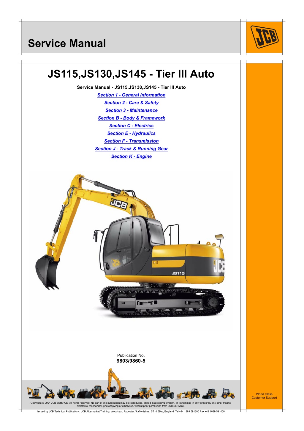
Service Manual JS115,JS130,JS145 - Tier III Auto Service Manual - JS115,JS130,JS145 - Tier III Auto Section 1 - General Information Section 2 - Care & Safety Section 3 - Maintenance Section B - Body & Framework Section C - Electrics Section E - Hydraulics Section F - Transmission Section J - Track & Running Gear Section K - Engine Publication No. 9803/9860-5 World Class Customer Support Copyright 2004 JCB SERVICE. All rights reserved. No part of this publication may be reproduced, stored in a retrieval system, or transmitted in any form or by any other means, electronic, mechanical, photocopying or otherwise, without prior permission from JCB SERVICE. Issued by JCB Technical Publications, JCB Aftermarket Training, Woodseat, Rocester, Staffordshire, ST14 5BW, England. Tel +44 1889 591300 Fax +44 1889 591400
Section 1 General Information Service Manual - JS115,JS130,JS145 - Tier III Auto Section 1 - General Information Section 2 - Care & Safety Section 3 - Maintenance Section B - Body & Framework Section C - Electrics Section E - Hydraulics Section F - Transmission Section J - Track & Running Gear Section K - Engine Publication No. 9803/9860-4 World Class Customer Support Copyright 2004 JCB SERVICE. All rights reserved. No part of this publication may be reproduced, stored in a retrieval system, or transmitted in any form or by any other means, electronic, mechanical, photocopying or otherwise, without prior permission from JCB SERVICE. Issued by JCB Technical Publications, JCB Aftermarket Training, Woodseat, Rocester, Staffordshire, ST14 5BW, England. Tel +44 1889 591300 Fax +44 1889 591400
Section 1 - General Information Contents Introduction About this Manual ...................................................................................... 1-1 Identifying Your Machine ........................................................................... 1-3 Page No. Torque Settings Zinc Plated Fasteners and Dacromet Fasteners ....................................... 1-5 Hydraulic Connections ............................................................................... 1-9 Service Tools Numerical List .......................................................................................... 1-13 Tool Detail Reference .............................................................................. 1-16 Service Consumables Sealing and Retaining Compounds ......................................................... 1-37 Terms and Definitions Colour Coding .......................................................................................... 1-39 1-i 1-i
https://www.ebooklibonline.com Hello dear friend! Thank you very much for reading. Enter the link into your browser. The full manual is available for immediate download. https://www.ebooklibonline.com
Section 1 - General Information Introduction About this Manual Machine Model and Serial Number machine without notice is reserved. No responsibility will be accepted for discrepancies which may occur between specifications of the machine and the descriptions contained in this publication. This manual provides information for the following model(s) in the JCB machine range: Finally, please remember above all else safety must come first! JCB JS115 from serial number 1703500 to 1703599. JCB JS115 from serial number 1777500 to 1777999. Section Numbering JCB JS130 from serial number 1535000 to 1535999. T11-005 The manual is compiled in sections, the first three are numbered and contain information as follows: JCB JS145 from serial number 1600011 to 1600999. Using the Service Manual General Information - includes torque settings and service tools. Care and Safety - includes warnings and cautions pertinent to aspects of workshop procedures etc. Maintenance - includes service schedules and recommended lubricants for all the machine. 1 T11-004 This publication is designed for the benefit of JCB Distributor Service Engineers who are receiving, or have received, training by JCB Technical Training Department. 2 3 These personnel should have a sound knowledge of workshop practice, safety procedures, and general techniques associated with the maintenance and repair of hydraulic earthmoving equipment. The remaining sections are alphabetically coded and deal with Dismantling, Overhaul etc. of specific components, for example: The illustrations in this publication are for guidance only. Where the machines differ, the text and/or the illustration will specify. Attachments Body and Framework, etc. A B General warnings in Section 2 are repeated throughout the manual, as well as specific warnings. Read all safety statements regularly, so you do not forget them. Section contents, technical data, circuit descriptions, operation descriptions etc. are inserted at the beginning of each alphabetically coded section. Renewal of oil seals, gaskets, etc., and any component showing obvious signs of wear or damage is expected as a matter of course. It is expected that components will be cleaned and lubricated where appropriate, and that any opened hose or pipe connections will be blanked to prevent excessive loss of hydraulic fluid and ingress of dirt. Where a torque setting is given as a single figure it may be varied by plus or minus 3%. Torque figures indicated are for dry threads, hence for lubricated threads may be reduced by one third. The manufacturer's policy is one of continuous improvement. The right to change the specification of the 1-1 1-1 9803/9860-4
Section 1 - General Information Introduction About this Manual Left Side, Right Side In this manual, 'left' A and 'right' B mean your left and right when you are seated correctly in the machine. B A C017280 Fig 1. Cross References T1-004_2 In this publication, page cross references are made by presenting the subject title printed in bold, italic and underlined. It is preceeded by the 'go to' symbol. The number of the page upon which the subject begins, is indicated within the brackets. For example: K References ( T T 1-2). K Cross 1-2 1-2 9803/9860-4
Section 1 - General Information Introduction Identifying Your Machine Identifying Your Machine Machine Identification Plate Typical Product Identification Number (PIN) Your machine has a data plate, located on the outside the cab as shown at A. The machine serial number is inscribed at B which is the base plate of the rear frame. 1 2 3 C 4 JCB JS11D 01421200 World Manufacturer Identification (JCB) 1 Machine Type and Model (JS11D= JS115) 2 Randomly Generated Check Letter. 3 Machine Serial Number (01421200) 4 T103401 Fig 2. 732821 Fig 3. 1-3 1-3 9803/9860-4
Section 1 - General Information Introduction Identifying Your Machine Typical Engine Identification Number If the engine is replaced by a new one, the data plate serial number will be wrong. Either stamp the new number on the plate or stamp out the old one. This will prevent the wrong number being quoted when you order replacement parts. The engine number is at A. A T020840 Fig 4. 4JJ a b 4JJ 578550 Engine Type a Engine Serial Number b 1-4 1-4 9803/9860-4
Section 1 - General Information Torque Settings Zinc Plated Fasteners and Dacromet Fasteners Torque Settings Zinc Plated Fasteners and Dacromet Fasteners T11-002 Introduction Bolts and Screws Some external fasteners on JCB machines are manufactured using an improved type of corrosion resistant finish. This type of finish is called Dacromet and replaces the original Zinc and Yellow Plating used on earlier machines. Use the following torque setting tables only where no torque setting is specified in the text. Note: Dacromet fasteners are lubricated as part of the plating process, do not lubricate. The two types of fasteners can be readily identified by colour and part number suffix. K ( T T 1-5). Torque settings are given for the following conditions: K Table 1. Fastener Types Condition 1 Table 1. Fastener Types Colour Un-lubricated fasteners Zinc fasteners Yellow plated fasteners Fastener Type Zinc and Yellow Dacromet Part No. Suffix Golden finish 'Z' (e.g. 1315/3712Z) Condition 2 Mottled silver finish 'D' (e.g. 1315/3712D) Zinc flake (Dacromet) fasteners Lubricated zinc and yellow plated fasteners Where there is a natural lubrication. For example, cast iron components Note: As the Dacromet fasteners have a lower torque setting than the Zinc and Yellow fasteners, the torque figures used must be relevant to the type of fastener. Note: A Dacromet bolt should not be used in conjunction with a Zinc or Yellow plated nut, as this could change the torque characteristics of the torque setting further. For the same reason, a Dacromet nut should not be used with a Zinc or Yellow plated bolt. Verbus Ripp Bolts Note: All bolts used on JCB machines are high tensile and must not be replaced by bolts of a lesser tensile specification. Fig 1. Note: Dacromet bolts, due to their high corrosion resistance are used in areas where rust could occur. Dacromet bolts are only used for external applications. They are not used in applications such as gearbox or engine joint seams or internal applications. Torque settings for these bolts are determined by the application. Refer to the relevant procedure for the required settings. 1-5 1-5 9803/9860-4
Section 1 - General Information Torque Settings Zinc Plated Fasteners and Dacromet Fasteners Table 2. Torque Settings - UNF Grade 'S' Fasteners Hexagon (A/F) in. Nm 7/16 11.2 1/2 22.3 9/16 40.0 5/8 64.0 3/4 98.00 13/16 140.0 15/16 196.0 1 1/8 343.0 1 15/16 547.0 1 1/2 814.0 1 7/8 1181.0 2 1/4 1646.0 Bolt Size Condition 1 kgf m 1.1 2.3 4.1 6.5 10.0 14.3 20.0 35.0 55.8 83.0 120.4 167.8 Condition 2 kgf m 1.0 2.0 3.7 5.8 9.0 12.8 18.0 31.5 50.2 74.6 108.4 151.0 in. 1/4 5/16 3/8 7/16 1/2 9/16 5/8 3/4 7/8 1 1 1/8 1 1/4 mm 6.3 7.9 9.5 11.1 12.7 14.3 15.9 19.0 22.2 25.4 31.7 38.1 lbf ft 8.3 16.4 29.5 47.2 72.3 103.2 144.6 253.0 403.4 600.4 871.1 1214.0 Nm 10.0 20.0 36.0 57.0 88.0 126.0 177.0 309.0 492.0 732.0 1063.0 1481.0 lbf ft 7.4 14.7 26.5 42.0 64.9 92.9 130.5 227.9 362.9 539.9 784.0 1092.3 Table 3. Torque Settings - Metric Grade 8.8 Fasteners Hexagon (A/F) Bolt Size Condition 1 Condition 2 ISO Metric Thread M5 M6 M8 M10 M12 M16 M20 M24 M30 M36 mm 5 6 8 10 12 16 20 24 30 36 mm 8 10 13 17 19 24 30 36 46 55 Nm 5.8 9.9 24.0 47.0 83.0 205.0 400.0 690.0 1372.0 2399.0 kgf m 0.6 1.0 2.4 4.8 8.5 20.9 40.8 70.4 139.9 244.6 lbf ft 4.3 7.3 17.7 34.7 61.2 151.2 295.0 508.9 1011.9 1769.4 Nm 5.2 9.0 22.0 43.0 74.0 184.0 360.0 621.0 1235.0 2159.0 kgf m 0.5 0.9 2.2 4.4 7.5 18.8 36.7 63.3 125.9 220.0 lbf ft 3.8 6.6 16.2 31.7 54.6 135.7 265.5 458.0 910.9 1592.4 1-6 1-6 9803/9860-4
Section 1 - General Information Torque Settings Zinc Plated Fasteners and Dacromet Fasteners Table 4. Metric Grade 10.9 Fasteners Hexagon (A/F) Bolt Size Condition 1 Condition 2 ISO Metric Thread M5 M6 M8 M10 M12 M16 M20 M24 M30 M36 mm 5 6 8 10 12 16 20 24 30 36 mm 8 10 13 17 19 24 30 36 46 55 Nm 8.1 13.9 34.0 67.0 116.0 288.0 562.0 971.0 1930.0 3374.0 kgf m 0.8 1.4 3.5 6.8 11.8 29.4 57.3 99.0 196.8 344.0 lbf ft 6.0 10.2 25.0 49.4 85.5 212.4 414.5 716.9 1423.5 2488.5 Nm 7.3 12.5 30.0 60.0 104.0 259.0 506.0 874.0 1737.0 3036.0 kgf m 0.7 1.3 3.0 6.1 10.6 26.4 51.6 89.1 177.1 309.6 lbf ft 5.4 9.2 22.1 44.2 76.7 191.0 373.2 644.6 1281.1 2239.2 Table 5. Metric Grade 12.9 Fasteners Hexagon (A/F) Bolt Size Condition 1 Condition 2 ISO Metric Thread M5 M6 M8 M10 M12 M16 M20 M24 M30 M36 mm 5 6 8 10 12 16 20 24 30 36 mm 8 10 13 17 19 24 30 36 46 55 Nm 9.8 16.6 40.0 80.0 139.0 345.0 674.0 1165.0 2316.0 4049.0 kgf m 1.0 1.7 4.1 8.1 14.2 35.2 68.7 118.8 236.2 412.9 lbf ft 7.2 12.2 29.5 59.0 102.5 254.4 497.1 859.2 1708.2 2986.4 Nm 8.8 15.0 36.0 72.0 125.0 311.0 607.0 1048.0 2084.0 3644.0 kgf m 0.9 1.5 3.7 7.3 12.7 31.7 61.9 106.9 212.5 371.6 lbf ft 6.5 11.1 26.5 53.1 92.2 229.4 447.7 773.0 1537.1 2687.7 1-7 1-7 9803/9860-4
Section 1 - General Information Torque Settings Zinc Plated Fasteners and Dacromet Fasteners Table 6. Torque Settings - Rivet Nut Bolts/Screws Bolt Size ISO Metric Thread mm M3 3 M4 4 M5 5 M6 6 M8 8 M10 10 M12 12 Nm 1.2 3.0 6.0 10.0 24.0 48.0 82.0 kgf m 0.1 0.3 0.6 1.0 2.5 4.9 8.4 lbf ft 0.9 2.0 4.5 7.5 18.0 35.5 60.5 Table 7. Torque Settings - Internal Hexagon Headed Cap Screws (Zinc) Bolt Size ISO Metric Thread M3 2.0 M4 6.0 M5 11.0 M6 19.0 M8 46.0 M10 91.0 M12 159.0 M16 395.0 M18 550.0 M20 770.0 M24 1332.0 Nm kgf m 0.2 0.6 1.1 1.9 4.7 9.3 16.2 40.0 56.0 79.0 136.0 lbf ft 1.5 4.5 8.0 14.0 34.0 67.0 117.0 292.0 406.0 568.0 983.0 1-8 1-8 9803/9860-4
Section 1 - General Information Torque Settings Hydraulic Connections Hydraulic Connections T11-003 'O' Ring Face Seal System Adaptors Screwed into Valve Blocks Adaptor screwed into valve blocks, seal onto an 'O' ring which is compressed into a 45 seat machined into the face of the tapped port. Table 8. Torque Settings - BSP Adaptors BSP Adaptor Size in. mm 1/4 19.0 3/8 22.0 1/2 27.0 5/8 30.0 3/4 32.0 1 38.0 1 1/4 50.0 Hexagon (A/F) Nm 18.0 31.0 49.0 60.0 81.0 129.0 206.0 kgf m 1.8 3.2 5.0 6.1 8.2 13.1 21.0 lbf ft 13.0 23.0 36.0 44.0 60.0 95.0 152.0 Table 9. Torque Settings - SAE Connections Hexagon (A/F) mm 15.9 20.0 - 28.0 19.1 46.0 - 54.0 22.2 95.0 - 105.0 27.0 130.0 - 140.0 1 1/16 - 12 31.8 1 5/16 - 12 38.1 1 5/8 47.6 SAE Tube Size 4 6 8 10 12 16 20 SAE Port Thread Size 7/16 - 20 9/16 - 18 3/4 - 16 7/8 - 14 Nm kgf m 2.0 - 2.8 4.7 - 5.5 9.7 - 10.7 13.2 - 14.3 19.4 - 21.4 29.6 - 31.6 28.5 - 38.7 lbf ft 16.5 - 18.5 34.0 - 40.0 69.0 - 77.0 96.0 - 104.0 141.0 - 155.0 216.0 - 230.0 210.0 - 280.0 190.0 - 210.0 290.0 - 310.0 280.0 - 380.0 1-9 1-9 9803/9860-4
Section 1 - General Information Torque Settings Hydraulic Connections Hoses Screwed into Adaptors Fig 2. Hoses 2-B screwed into adaptors 2-A seal onto an `O' ring 2-C which is compressed into a 45 seat machined into the face of the adaptor port. Note: Dimension 2-D will vary depending upon the torque applied. Table 10. BSP Hose - Torque Settings Hexagon (A/F) mm 14.0 14.0 - 16.00 19.0 24.0 - 27.0 22.0 33.0 - 40.0 27.0 44.0 - 50.0 30.0 58.0 - 65.0 32.0 84.0 - 92.0 38.0 115.0 - 126.0 50.0 189.0 - 200.0 55.0 244.0 - 260.0 BSP Hose Size in. 1/8 1/4 3/8 1/2 5/8 3/4 1 1 1/4 1 1/2 Nm kgf m 1.4 - 1.6 2.4 - 2.7 3.4 - 4.1 4.5 - 5.1 5.9 - 6.6 8.6 - 9.4 11.7 - 12.8 19.3 - 20.4 24.9 - 26.5 lbf ft 10.3 - 11.8 17.7 - 19.9 24.3 - 29.5 32.4 - 36.9 42.8 - 47.9 61.9 - 67.8 84.8 - 92.9 139.4 - 147.5 180.0 - 191.8 1-10 1-10 9803/9860-4
Section 1 - General Information Torque Settings Hydraulic Connections Adaptors into Component Connections with Bonded Washers Table 11. BSP Adaptors with Bonded Washers - Torque Settings BSP Size Nm in. 1/8 20.0 1/4 34.0 3/8 75.0 1/2 102.0 5/8 122.0 3/4 183.0 1 203.0 1 1/4 305.0 1 1/2 305.0 kgf m 2.1 3.4 7.6 10.3 12.4 18.7 20.7 31.0 31.0 lbf ft 15.0 25.0 55.0 75.0 90.0 135.0 150.0 225.0 225.0 1-11 1-11 9803/9860-4
Section 1 - General Information Torque Settings Hydraulic Connections 'Torque Stop' Hose System Fig 3. `Torque Stop' Hoses 3-B screwed into adaptors 3-A seal onto an 'O' ring 3-C which is compressed into a 45 seat machined in the face of the adaptor port. To prevent the 'O' ring being damages as a result of over tightening, 'Torque Stop' Hoses have an additional shoulder 3-D, which acts as a physical stop. Note: Minimum dimension 3-E fixed by shoulder 3-D. Table 12. BSP `Torque Stop' Hose - Torque Settings BSP Hose Size Hexagon (A/F) in. mm 1/8 14.0 1/4 19.0 3/8 22.0 1/2 27.0 5/8 30.0 3/4 32.0 1 38.0 1 1/4 50.0 1 1/2 55.0 Nm 14.0 27.0 40.0 55.0 65.0 95.0 120.0 189.0 244.0 kgf m 1.4 2.7 4.1 5.6 6.6 9.7 12.2 19.3 24.9 lbf ft 10.0 20.0 30.0 40.0 48.0 70.0 89.0 140.0 180.0 1-12 1-12 9803/9860-4
Section 2 Care & Safety Service Manual - JS115,JS130,JS145 - Tier III Auto Section 1 - General Information Section 2 - Care & Safety Section 3 - Maintenance Section B - Body & Framework Section C - Electrics Section E - Hydraulics Section F - Transmission Section J - Track & Running Gear Section K - Engine Publication No. 9803/9860-4 World Class Customer Support Copyright 2004 JCB SERVICE. All rights reserved. No part of this publication may be reproduced, stored in a retrieval system, or transmitted in any form or by any other means, electronic, mechanical, photocopying or otherwise, without prior permission from JCB SERVICE. Issued by JCB Technical Publications, JCB Aftermarket Training, Woodseat, Rocester, Staffordshire, ST14 5BW, England. Tel +44 1889 591300 Fax +44 1889 591400
Section 2 - Care and Safety Contents Safety Notices Important Information ................................................................................ 2-1 The Operator Manual ............................................................................2-1 Safety Warnings ....................................................................................2-1 Safety Check List ....................................................................................... 2-2 Safety - Yours and Others .....................................................................2-2 General Safety ......................................................................................2-2 Operating Safety ...................................................................................2-4 Maintenance Safety ...............................................................................2-7 Safety Labels ........................................................................................... 2-12 Introduction ..........................................................................................2-12 Safety Label Identification ...................................................................2-13 Page No. 2-i 2-i
Section 2 - Care and Saftey Safety Notices Important Information T1-042 The Operator Manual Safety Warnings !MWARNING This safety alert system identifies important safety messages in this manual. When you see this symbol, be alert, your safety is involved, carefuly read the message that follows, and inform other operators. You and others can be killed or seriously injured if you operate or maintain the machine without first studying the Operator Manual. You must understand and follow the instructions in the Operator Manual. If you do not understand anything, ask your employer or JCB dealer to explain it. In this publication and on the machine, there are safety notices. Each notice starts with a signal word. The signal word meanings are given below. INT-1-4-2 Do not operate the machine without an Operator Manual, or if there is anything on the machine you do not understand. !MDANGER Denotes an extreme hazard exists. If proper precautions are not taken, it is highly probable that the operator (or others) could be killed or seriously injured. Treat the Operator Manual as part of the machine. Keep it clean and in good condition. Replace the Operator Manual immediately if it is lost, damaged or becomes unreadable. INT-1-2-1 !MWARNING Denotes a hazard exists. If proper precautions are not taken, the operator (or others) could be killed or seriously injured. INT-1-2-2 !MCAUTION Denotes a reminder of safety practices. Failure to follow these safety practices could result in injury to the operator (or others) and possible damage to the machine. INT-1-2-3 2-1 2-1 9803/9860-4
Section 2 - Care and Saftey Safety Notices Safety Check List Safety Check List P11-1007_3 Safety - Yours and Others General Safety INT-1-3-1_3 T1-043 !MWARNING All machinery can be hazardous. When a machine is correctly operated and properly maintained, it is a safe machine to work with. But when it is carelessly operated or poorly maintained it can become a danger to you (the operator) and others. To operate the machine safely you must know the machine and have the skill to use it. You must abide by all relevant laws, health and safety regulations that apply to the country you are operating in. The Operator Manual instructs you on the machine, its controls and its safe operation; it is not a training manual. If you are a new operator, get yourself trained in the skills of using a machine before trying to work with it. If you don't, you will not do your job well, and you will be a danger to yourself and others. In this manual and on the machine you will find warning messages. Read and understand them. They tell you of potential hazards and how to avoid them. If you do not fully understand the warning messages, ask your employer or JCB distributor to explain them. But safety is not just a matter of responding to the warnings. All the time you are working on or with the machine you must be thinking what hazards there might be and how to avoid them. INT-1-4-1 !MWARNING Care and Alertness Do not work with the machine until you are sure that you can control it. All the time you are working with or on the machine, take care and stay alert. Always be careful. Always be alert for hazards. Do not start any job until you are sure that you and those around you will be safe. INT-1-3-5 !MWARNING Clothing If you are unsure of anything, about the machine or the job, ask someone who knows. Do not assume anything. You can be injured if you do not wear the proper clothing. Loose clothing can get caught in the machinery. Wear protective clothing to suit the job. Examples of protective clothing are: a hard hat, safety shoes, safety glasses, a well fitting overall, ear- protectors and industrial gloves. Keep cuffs fastened. Do not wear a necktie or scarf. Keep long hair restrained. Remove rings, watches and personal jewellery. Remember BE CAREFUL BE ALERT BE SAFE INT-1-3-6_2 !MWARNING Alcohol and Drugs It is extremely dangerous to operate machinery when under the influence of alcohol or drugs. Do not consume alcoholic drinks or take drugs before or while operating the machine or attachments. Be aware of medicines which can cause drowsiness. INT-1-3-9_2 2-2 2-2 9803/9860-4
Section 2 - Care and Saftey Safety Notices Safety Check List !MWARNING Feeling Unwell !MDANGER Lightning Do not attempt to operate the machine if you are feeling unwell. By doing so you could be a danger to yourself and those you work with. Lightning can kill you. Do not use the machine if there is lightning in your area. 5-1-1-2 8-1-2-4 !MWARNING !MWARNING Mobile Phones Machine Modifications This machine is manufactured in compliance with legislative and other requirements. It should not be altered in any way which could affect or invalidate any of these requirements. For advice consult your JCB Distributor. Switch off your mobile phone before entering an area with a potentially explosive atmosphere. Sparks in such an area could cause an explosion or fire resulting in death or serious injury. INT-1-3-10_2 Switch off and do not use your mobile phone when refuelling the machine. INT-3-3-9 !MWARNING Lifting Equipment You can be injured if you use incorrect or faulty lifting equipment. You must identify the weight of the item to be lifted then choose lifting equipment that is strong enough and suitable for the job. Make sure that lifting equipment is in good condition and complies with all local regulations. INT-1-3-7_2 !MWARNING Raised Equipment Never walk or work under raised equipment unless it is supported by a mechanical device. Equipment which is supported only by a hydraulic device can drop and injure you if the hydraulic system fails or if the control is operated (even with the engine stopped). Make sure that no-one goes near the machine while you install or remove the mechanical device. 13-2-3-7_3 !MWARNING Raised Machine NEVER position yourself or any part of your body under a raised machine which is not properly supported. If the machine moves unexpectedly you could become trapped and suffer serious injury or be killed. INT-3-3-7_1 2-3 2-3 9803/9860-4
Section 2 - Care and Saftey Safety Notices Safety Check List !MWARNING Work Sites Operating Safety !MWARNING Machine Condition Work sites can be hazardous. Inspect the site before working on it. You could be killed or injured if the ground gives way under your machine or if piled material collapses onto it. Check for potholes and hidden debris, logs, ironwork etc. Any of these could cause you to lose control of your machine. Check for utilities such as electric cables (overhead and underground), gas and water pipes etc. Mark the positions of the underground cables and pipes. Make sure that you have enough clearance beneath overhead cables and structures. A defective machine can injure you or others. Do not operate a machine which is defective or has missing parts. Make sure the maintenance procedures in this manual are completed before using the machine. INT-2-1-2_2 !MWARNING Machine Limits INT-2-2-1_2 Operating the machine beyond its design limits can damage the machine, it can also be dangerous. Do not operate the machine outside its limits. Do not try to upgrade the machine performance with unapproved modifications. !MWARNING Communications Bad communications can cause accidents. Keep people around you informed of what you will be doing. If you will be working with other people, make sure any hand signals that may be used are understood by everybody. Work sites can be noisy, do not rely on spoken commands. INT-2-1-4 !MWARNING Engine/Steering Failure If the engine or steering fails, stop the machine as quickly as possible. Do not operate the machine until the fault has been corrected. INT-2-2-3 !MWARNING INT-2-1-5 Parking !MWARNING An incorrectly parked machine can move without an operator. Follow the instructions in the Operator Manual to park the machine correctly. Exhaust Gases Breathing the machine exhaust gases can harm and possibly kill you. Do not operate the machine in closed spaces without making sure there is good ventilation. If possible, fit an exhaust extension. If you begin to feel drowsy, stop the machine at once and get into fresh air. INT-2-2-4_2 !MWARNING Banks and Trenches Banked material and trenches can collapse. Do not work or drive too close to banks and trenches where there is danger of collapse. INT-2-1-10_2 INT-2-2-5 !MWARNING Safety Barriers Unguarded machines in public places can be dangerous. In public places, or where your visibility is reduced, place barriers around the work area to keep people away. INT-2-2-8 2-4 2-4 9803/9860-4
Section 2 - Care and Saftey Safety Notices Safety Check List !MDANGER Sparks !MWARNING Keep the machine controls clean and dry. Your hands and feet could slide off slippery controls. If that happens you could lose control of the machine. Explosions and fire can be caused by sparks from the exhaust or the electrical system. Do not use the machine in closed areas where there is flammable material, vapour or dust. 2-2-3-6 !MWARNING INT-2-2-10 !MWARNING Electrical Power Cables You could be electrocuted or badly burned if you get the machine or its attachments too close to electrical power cables. Hazardous Atmospheres This machine is designed for use in normal out door atmospheric conditions. It should not be used in an enclosed area without adequate ventilation. Do not use the machine in atmosphere, i.e. combustible vapours, gas or dust, without first consulting your JCB Distributor. You are strongly advised to make sure that the safety arrangements on site comply with the local laws and regulations concerning work near electric power lines. a potentially explosive Before you start using the machine, check with your electricity supplier if there are any buried power cables on the site. INT-2-1-14 !MCAUTION There is a minimum clearance required for working beneath overhead power cables. You must obtain details from your local electricity supplier. Regulations Obey all laws, work site and local regulations which affect you and your machine. 2-2-5-4 INT-1-3-3 !MCAUTION !MWARNING Practice If you have an attachment which is not covered in the Operator Manual do not install it, use it or remove it until you have obtained, read and understood the pertinent information. Install attachments only on the machines for which they were designed. You or others can be killed or seriously injured if you do unfamiliar operations without first practising them. Practise away from the work site on a clear area. Keep other people away. Do not perform new operations until you are sure you can do them safely. 5-5-1-1_2 INT-2-1-1 !MWARNING !MWARNING Use only the JCB approved attachments that are specified for your machine. Operating with non- specified attachments can overload the machine, causing possible damage and machine instability which could result in injury to yourself or others. Airborne particles of light combustible material such as straw, grass, wood shavings, etc. must not be allowed to accumulate within the engine compartment or in the propshaft guards (when fitted). Inspect these areas frequently and clean at the beginning of each work shift or more often if required. Before opening the engine cover, ensure that the top is clear of debris. The use of non-approved attachments could invalidate your warranty. 2-4-5-2_1 5-3-1-12_3 2-5 2-5 9803/9860-4
Section 2 - Care and Saftey Safety Notices Safety Check List !MDANGER Working Platform !MWARNING Visibility Using the machine as a working platform is hazardous; you can fall off and be killed or injured. Never use the machine as a working platform. Accidents can be caused by working in poor visibility. Use your lights to improve visibility. Keep the road lights, windows and mirrors clean. 5-1-5-9 Do not operate the machine if you cannot see clearly. !MWARNING Machine Safety 5-1-4-7 !MWARNING Stop work at once if a fault develops. Abnormal sounds and smells can be signs of trouble. Inspect and repair before resuming work. Keep Your Hands and Feet Inside the Vehicle When using the machine, keep your hands and feet clear of moving parts. Keep your hands and feet within the operator compartment while the vehicle is in motion. 8-1-2-3 !MWARNING 13-1-1-17 Touching hot surfaces can burn skin. The engine and machine components will be hot after the unit has been running. Allow the engine and components to cool before servicing the unit. !MWARNING Controls You or others can be killed or seriously injured if you operate the control levers from outside the machine. Operate the control levers only when you are correctly seated. 10-1-1-40 !MWARNING Travelling at High Speeds 0179_2 Travelling at high speeds can cause accidents. Do not reverse in a high gear with full throttle. Always travel at a safe speed to suit working conditions. !MCAUTION Passengers INT-5-3-3 Passengers in or on the machine can cause accidents. Do not carry passengers. !MWARNING INT-2-2-2_1 The engine has exposed rotating parts. Switch OFF the engine before working in the engine compartment. Do not use the machine with the engine cover open. !MWARNING Fires 5-2-6-5 If your machine is equipped with a fire extinguisher, make sure it is checked regularly. Keep it in the correct machine location until you need to use it. !MWARNING You could be killed or seriously injured if you operate a machine with a damaged or missing ROPS/FOPS. If the Roll Over Protection Structure (ROPS)/Falling Objects Protection Structure (FOPS) has been in an accident, do not use the machine until the structure has been renewed. Modifications and repairs that are not approved by the manufacturer may be dangerous and will invalidate the ROPS/FOPS certification. Do not use water to put out a machine fire, you could spread an oil fire or get a shock from an electrical fire. Use carbon dioxide, dry extinguishers. Contact your nearest fire department as quickly as possible. Firefighters should use self- contained breathing apparatus. chemical or foam INT-3-2-7_2 INT-2-1-9_6 2-6 2-6 9803/9860-4
Section 2 - Care and Saftey Safety Notices Safety Check List !MWARNING Maintenance Safety Should the machine start to roll over, you can be crushed if you try to leave the cab. If the machine starts to roll over, do not try and jump from the cab. Stay in the cab, with your seat belt fastened. !MWARNING Communications Bad communications can cause accidents. If two or more people are working on the machine, make sure each is aware of what the others are doing. Before starting the engine make sure the others are clear of the danger areas; examples of danger areas are: the rotating blades and belt on the engine, the attachments and linkages, and anywhere beneath or behind the machine. People can be killed or injured if these precautions are not taken. INT-2-1-12 !MWARNING Seat Belt Operating the machine without a seat belt can be dangerous. Before starting the engine, make sure your seat belt is fastened. Check the tightness and condition of the seat belt securing bolts regularly (see maintenance schedules). INT-3-1-5 !MWARNING INT-2-1-8_1 Repairs If your machine does not function correctly in any way, get it repaired straight away. Neglect of necessary repairs could result in an accident or affect your health. Do not try to do repairs or any other type of maintenance work you do not understand. To avoid injury and/or damage get the work done by a specialist engineer. GEN-1-5_2 !MWARNING Metal Splinters You can be injured by flying metal splinters when driving metal pins in or out. Use a soft faced hammer or copper pin to remove and fit metal pins. Always wear safety glasses. INT-3-1-3_2 !MWARNING Electrical Circuits Understand the electrical circuit before connecting or disconnecting an electrical component. A wrong connection can cause injury and/or damage. INT-3-1-4 2-7 2-7 9803/9860-4
Suggest: If the above button click is invalid. Please download this document first, and then click the above link to download the complete manual. Thank you so much for reading
Section 2 - Care and Saftey Safety Notices Safety Check List !MWARNING Fluid Under Pressure !MCAUTION It is illegal to pollute drains, sewers or the ground. Clean up all spilt fluids and/or lubricants. Fine jets of fluid at high pressure can penetrate the skin. Keep face and hands well clear of fluid under pressure and wear protective glasses and gloves. Hold a piece of cardboard close to suspected leaks and then inspect the cardboard for signs of fluid. If fluid penetrates your skin, get medical help immediately. Used fluids and/or lubricants, filters and contaminated materials must be disposed of in accordance with local regulations. Use authorised waste disposal sites. INT-3-2-14 !MWARNING INT-3-1-10_3 !MWARNING Soft Ground A machine can sink into soft ground. Never work under a machine on soft ground. Hydraulic Pressure Hydraulic fluid at system pressure can injure you. Before connecting or removing any hydraulic hose, residual hydraulic pressure trapped in the service hose line must be vented. Make sure the hose service line has been vented before connecting or removing hoses. Make sure the engine cannot be started while the hoses are open. INT-3-2-4 !MWARNING Always wear safety glasses when dismantling assemblies containing components under pressure from springs. This will protect against eye injury from components accidentally flying out. INT-3-1-11_2 GEN-6-2 !MWARNING !MCAUTION Rams Fuel Fuel is flammable; keep naked flames away from the fuel system. Stop the engine immediately if a fuel leak is suspected. Do not smoke while refuelling or working on the fuel system. Do not refuel with the engine running. Completely wipe off any spilt fuel which could cause a fire. There could be a fire and injury if you do not follow these precautions. The efficiency of the rams will be affected if they are not kept free of solidified dirt. Clean dirt from around the rams regularly. When leaving or parking the machine, close all rams if possible to reduce the risk of weather corrosion. INT-3-2-10 INT-3-2-2_3 !MCAUTION !MWARNING Oil Cleaning Cleaning metal parts with incorrect solvents can cause corrosion. Use only recommended cleaning agents and solvents. Oil is toxic. If you swallow any oil, do not induce vomiting, seek medical advice. Used engine oil contains harmful contaminants which can cause skin cancer. Do not handle used engine oil more than necessary. Always use barrier cream or wear gloves to prevent skin contact. Wash skin contaminated with oil thoroughly in warm soapy water. Do not use petrol, diesel fuel or paraffin to clean your skin. INT-3-2-11 !MWARNING When using cleaning agents, solvents or other chemicals, you must adhere to the manufacturer's instructions and safety precautions. INT-3-2-3 GEN-1-9 2-8 2-8 9803/9860-4
https://www.ebooklibonline.com Hello dear friend! Thank you very much for reading. Enter the link into your browser. The full manual is available for immediate download. https://www.ebooklibonline.com