JCB 722 Articulated Dump Truck Service Repair Manual Instant Download (Serial No From 833000 to 833200; From 833201 to 833999)
Please open the website below to get the complete manualnn//

Download Presentation

Please find below an Image/Link to download the presentation.
The content on the website is provided AS IS for your information and personal use only. It may not be sold, licensed, or shared on other websites without obtaining consent from the author. Download presentation by click this link. If you encounter any issues during the download, it is possible that the publisher has removed the file from their server.
E N D
Presentation Transcript
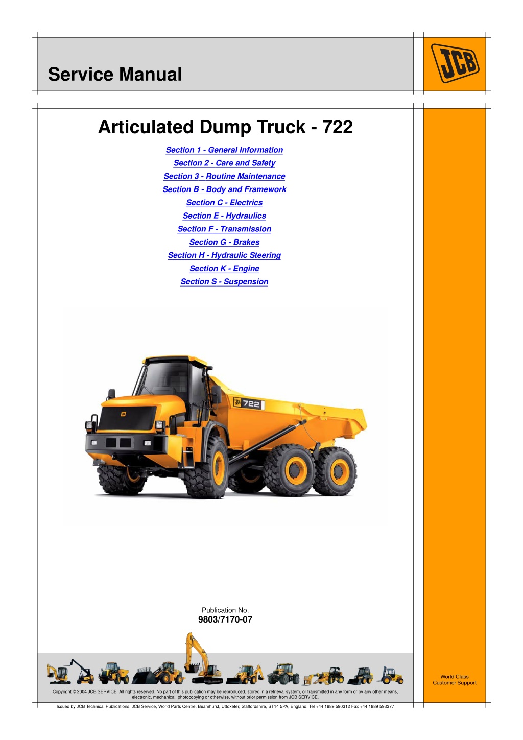
Service Manual Articulated Dump Truck - 722 Section 1 - General Information Section 2 - Care and Safety Section 3 - Routine Maintenance Section B - Body and Framework Section C - Electrics Section E - Hydraulics Section F - Transmission Section G - Brakes Section H - Hydraulic Steering Section K - Engine Section S - Suspension Publication No. 9803/7170-07 World Class Customer Support Copyright 2004 JCB SERVICE. All rights reserved. No part of this publication may be reproduced, stored in a retrieval system, or transmitted in any form or by any other means, electronic, mechanical, photocopying or otherwise, without prior permission from JCB SERVICE. Issued by JCB Technical Publications, JCB Service, World Parts Centre, Beamhurst, Uttoxeter, Staffordshire, ST14 5PA, England. Tel +44 1889 590312 Fax +44 1889 593377
Section 1 General Information Section 1 - General Information Section 2 - Care and Safety Section 3 - Routine Maintenance Section B - Body and Framework Section C - Electrics Section E - Hydraulics Section F - Transmission Section G - Brakes Section H - Hydraulic Steering Section K - Engine Section S - Suspension Publication No. 9803/7170-04 World Class Customer Support Copyright 2004 JCB SERVICE. All rights reserved. No part of this publication may be reproduced, stored in a retrieval system, or transmitted in any form or by any other means, electronic, mechanical, photocopying or otherwise, without prior permission from JCB SERVICE. Issued by JCB Technical Publications, JCB Service, World Parts Centre, Beamhurst, Uttoxeter, Staffordshire, ST14 5PA, England. Tel +44 1889 590312 Fax +44 1889 593377
Section 1 - General Information Contents Identification Vehicle Identification ................................................................................ 1 - 1 Vehicle Identification Plate ................................................................. 1 - 1 Explanation of the Vehicle Identification Number (VIN) ...................... 1 - 1 Unit Identification ................................................................................ 1 - 1 Page No. Torque Settings Zinc Plated Fasteners and Dacromet Fasteners ..................................... 1 - 3 Introduction ......................................................................................... 1 - 3 Bolts and Screws ................................................................................ 1 - 3 Service Tools Numerical List Section B - Body and Framework .................................... 1 - 7 Section B - Body and Framework ............................................................ 1 - 8 Numerical List Section C - Electrics ...................................................... 1 - 11 Section C - Electrics .............................................................................. 1 - 12 Numerical List Section E - Hydraulics ................................................... 1 - 13 Section E - Hydraulics ........................................................................... 1 - 15 Numerical List Section F - Transmission ............................................... 1 - 18 Section F - Transmission ....................................................................... 1 - 19 Numerical List Section K - Transmission ............................................... 1 - 22 Section K - Engine ................................................................................. 1 - 23 Sealing and Retaining Compounds Sealing and Retaining Compounds ....................................................... 1 - 24 Towing General .................................................................................................. 1 - 25 Preparation for Towing ..................................................................... 1 - 25 Hydraulic Hoses Connecting/Disconnecting ..................................................................... 1 - 27 Venting Hydraulic Pressure .............................................................. 1 - 27 Connecting the Hoses ...................................................................... 1 - 27 Disconnecting the Hoses .................................................................. 1 - 27 Hydraulics Hydraulic Contamination ....................................................................... 1 - 29 Hydraulic Fluid Quality ..................................................................... 1 - 29 Effects of Contamination .................................................................. 1 - 29 Cleaning Operation .......................................................................... 1 - 29 Procedure ......................................................................................... 1 - 29 Contamination Standards ................................................................. 1 - 29 Filters ................................................................................................ 1 - 29 1 - i 1 - i
https://www.ebooklibonline.com Hello dear friend! Thank you very much for reading. Enter the link into your browser. The full manual is available for immediate download. https://www.ebooklibonline.com
Section 1 - General Information Identification Vehicle Identification Vehicle Identification Plate D E Manufacturing Location E - England Machine Serial Number 0537000 Your machine has an identification plate 1T, mounted on the left side of the machine as shown. The serial number of the machine and its major units are stamped on the plate The serial number of each major unit is also stamped on the unit itself. If a major unit is replaced by a new one, the serial number on the identification plate will be wrong. Either stamp the new number of the unit on the identification plate, or simply stamp out the old number. This will prevent the wrong unit number being quoted when replacement parts are ordered. The machine and engine serial numbers can help identify exactly the type of equipment you have. Unit Identification The engine serial number is stamped on a plate 2Y, which is fastened to the left side of the cylinder block. T 433270-C1 Fig 1. Explanation of the Vehicle Identification Number (VIN) SLP A 722 B 3 C E D 537000 E Y A B C World Manufacturer Identification SLP = JCB Machine Model Year of Manufacture P = 1993 R = 1994 S = 1995 T = 1996 722 V W X Y = 19971 = 2001 = 19982 = 2002 = 19993 = 2003 = 20004 = 2004 432870-C1 Fig 2. 1 - 1 1 - 1 9803/7170-04
Section 1 - General Information Identification Vehicle Identification The Transmission serial number is stamped on a plate 3Z, located at the bottom front of the transmission unit, as shown. Z Fig 3. 1 - 2 1 - 2 9803/7170-04
Section 1 - General Information Torque Settings Zinc Plated Fasteners and Dacromet Fasteners Torque Settings Zinc Plated Fasteners and Dacromet Fasteners T11-002 Introduction Bolts and Screws Some external fasteners on JCB machines are manufactured using an improved type of corrosion resistant finish. This type of finish is called Dacromet and replaces the original Zinc and Yellow Plating used on earlier machines. Use the following torque setting tables only where no torque setting is specified in the text. Note: Dacromet fasteners are lubricated as part of the plating process, do not lubricate. The two types of fasteners can be readily identified by colour and part number suffix. K ( T T 1-3). Torque settings are given for the following conditions: K Table 1. Fastener Types Condition 1 Table 1. Fastener Types Colour Un-lubricated fasteners Zinc fasteners Yellow plated fasteners Fastener Type Zinc and Yellow Dacromet Part No. Suffix Golden finish 'Z' (e.g. 1315/3712Z) Condition 2 Mottled silver finish 'D' (e.g. 1315/3712D) Zinc flake (Dacromet) fasteners Lubricated zinc and yellow plated fasteners Where there is a natural lubrication. For example, cast iron components Note: As the Dacromet fasteners have a lower torque setting than the Zinc and Yellow fasteners, the torque figures used must be relevant to the type of fastener. Note: A Dacromet bolt should not be used in conjunction with a Zinc or Yellow plated nut, as this could change the torque characteristics of the torque setting further. For the same reason, a Dacromet nut should not be used with a Zinc or Yellow plated bolt. Verbus Ripp Bolts Note: All bolts used on JCB machines are high tensile and must not be replaced by bolts of a lesser tensile specification. Fig 4. Note: Dacromet bolts, due to their high corrosion resistance are used in areas where rust could occur. Dacromet bolts are only used for external applications. They are not used in applications such as gearbox or engine joint seams or internal applications. Torque settings for these bolts are determined by the application. Refer to the relevant procedure for the required settings. 1 - 3 1 - 3 9803/7170-04
Section 1 - General Information Torque Settings Zinc Plated Fasteners and Dacromet Fasteners Table 2. Torque Settings - UNF Grade 'S' Fasteners Hexagon (A/F) in. Nm 7/16 11.2 1/2 22.3 9/16 40.0 5/8 64.0 3/4 98.00 13/16 140.0 15/16 196.0 1 1/8 343.0 1 15/16 547.0 1 1/2 814.0 1 7/8 1181.0 2 1/4 1646.0 Bolt Size Condition 1 kgf m 1.1 2.3 4.1 6.5 10.0 14.3 20.0 35.0 55.8 83.0 120.4 167.8 Condition 2 kgf m 1.0 2.0 3.7 5.8 9.0 12.8 18.0 31.5 50.2 74.6 108.4 151.0 in. 1/4 5/16 3/8 7/16 1/2 9/16 5/8 3/4 7/8 1 1 1/8 1 1/4 mm 6.3 7.9 9.5 11.1 12.7 14.3 15.9 19.0 22.2 25.4 31.7 38.1 lbf ft 8.3 16.4 29.5 47.2 72.3 103.2 144.6 253.0 403.4 600.4 871.1 1214.0 Nm 10.0 20.0 36.0 57.0 88.0 126.0 177.0 309.0 492.0 732.0 1063.0 1481.0 lbf ft 7.4 14.7 26.5 42.0 64.9 92.9 130.5 227.9 362.9 539.9 784.0 1092.3 Table 3. Torque Settings - Metric Grade 8.8 Fasteners Hexagon (A/F) Bolt Size Condition 1 Condition 2 ISO Metric Thread M5 M6 M8 M10 M12 M16 M20 M24 M30 M36 mm 5 6 8 10 12 16 20 24 30 36 mm 8 10 13 17 19 24 30 36 46 55 Nm 5.8 9.9 24.0 47.0 83.0 205.0 400.0 690.0 1372.0 2399.0 kgf m 0.6 1.0 2.4 4.8 8.5 20.9 40.8 70.4 139.9 244.6 lbf ft 4.3 7.3 17.7 34.7 61.2 151.2 295.0 508.9 1011.9 1769.4 Nm 5.2 9.0 22.0 43.0 74.0 184.0 360.0 621.0 1235.0 2159.0 kgf m 0.5 0.9 2.2 4.4 7.5 18.8 36.7 63.3 125.9 220.0 lbf ft 3.8 6.6 16.2 31.7 54.6 135.7 265.5 458.0 910.9 1592.4 1 - 4 1 - 4 9803/7170-04
Section 1 - General Information Torque Settings Zinc Plated Fasteners and Dacromet Fasteners Table 4. Metric Grade 10.9 Fasteners Hexagon (A/F) Bolt Size Condition 1 Condition 2 ISO Metric Thread M5 M6 M8 M10 M12 M16 M20 M24 M30 M36 mm 5 6 8 10 12 16 20 24 30 36 mm 8 10 13 17 19 24 30 36 46 55 Nm 8.1 13.9 34.0 67.0 116.0 288.0 562.0 971.0 1930.0 3374.0 kgf m 0.8 1.4 3.5 6.8 11.8 29.4 57.3 99.0 196.8 344.0 lbf ft 6.0 10.2 25.0 49.4 85.5 212.4 414.5 716.9 1423.5 2488.5 Nm 7.3 12.5 30.0 60.0 104.0 259.0 506.0 874.0 1737.0 3036.0 kgf m 0.7 1.3 3.0 6.1 10.6 26.4 51.6 89.1 177.1 309.6 lbf ft 5.4 9.2 22.1 44.2 76.7 191.0 373.2 644.6 1281.1 2239.2 Table 5. Metric Grade 12.9 Fasteners Hexagon (A/F) Bolt Size Condition 1 Condition 2 ISO Metric Thread M5 M6 M8 M10 M12 M16 M20 M24 M30 M36 mm 5 6 8 10 12 16 20 24 30 36 mm 8 10 13 17 19 24 30 36 46 55 Nm 9.8 16.6 40.0 80.0 139.0 345.0 674.0 1165.0 2316.0 4049.0 kgf m 1.0 1.7 4.1 8.1 14.2 35.2 68.7 118.8 236.2 412.9 lbf ft 7.2 12.2 29.5 59.0 102.5 254.4 497.1 859.2 1708.2 2986.4 Nm 8.8 15.0 36.0 72.0 125.0 311.0 607.0 1048.0 2084.0 3644.0 kgf m 0.9 1.5 3.7 7.3 12.7 31.7 61.9 106.9 212.5 371.6 lbf ft 6.5 11.1 26.5 53.1 92.2 229.4 447.7 773.0 1537.1 2687.7 1 - 5 1 - 5 9803/7170-04
Section 1 - General Information Torque Settings Zinc Plated Fasteners and Dacromet Fasteners Table 6. Torque Settings - Rivet Nut Bolts/Screws Bolt Size ISO Metric Thread mm M3 3 M4 4 M5 5 M6 6 M8 8 M10 10 M12 12 Nm 1.2 3.0 6.0 10.0 24.0 48.0 82.0 kgf m 0.1 0.3 0.6 1.0 2.5 4.9 8.4 lbf ft 0.9 2.0 4.5 7.5 18.0 35.5 60.5 Table 7. Torque Settings - Internal Hexagon Headed Cap Screws (Zinc) Bolt Size ISO Metric Thread M3 2.0 M4 6.0 M5 11.0 M6 19.0 M8 46.0 M10 91.0 M12 159.0 M16 395.0 M18 550.0 M20 770.0 M24 1332.0 Nm kgf m 0.2 0.6 1.1 1.9 4.7 9.3 16.2 40.0 56.0 79.0 136.0 lbf ft 1.5 4.5 8.0 14.0 34.0 67.0 117.0 292.0 406.0 568.0 983.0 1 - 6 1 - 6 9803/7170-04
Section 1 - General Information Sealing and Retaining Compounds Sealing and Retaining Compounds Sealing and Retaining Compounds Sealing and Retaining Compounds T11-001_3 Table 8. Type JCB Multi-Gasket Description A medium strength sealant suitable for all sizes of gasket flanges, and for hydraulic fittings of 25-65 mm diameter. A high strength locking fluid for use with threaded components. Gasketing for all sizes of flange where the strength of the joint is important. For all retaining parts which are unlikely to be dismantled. A medium strength locking fluid for sealing and retaining nuts, bolts, and screws up to 50 mm diameter, and for hydraulic fittings up to 25 mm diameter. A high strength locking fluid for sealing and retaining nuts, bolts, and screws up to 50 mm diameter, and for hydraulic fittings up to 25 mm diameter. A medium strength thread sealing compound. A cleaning primer which speeds the curing rate of anaerobic products. Part No. 4102/1212 Quantity 50 ml JCB High Strength Threadlocker 4102/0551 50 ml JCB Retainer (High Strength) 4101/0651 50 ml JCB Threadlocker and Sealer 4101/0250 4101/0251 10 ml 50 ml JCB Threadlocker and Sealer (High Strength) 4101/0550 4101/0552 10 ml 200 ml JCB Threadseal JCB Activator 4102/1951 4104/0251 4104/0253 4104/1557 50 ml 200 ml (Aerosol) 1 ltr (Bottle) 400 ml (Aerosol) JCB Cleaner/Degreaser For degreasing components prior to use of anaerobic adhesives and sealants. For one pane of glass; comprises of: Direct Glazing Kit 993/55700 1 x Ultra Fast Adhesive (310 ml) 1 x Active Wipe 205 (30 ml) 1 x Black Primer 206J (30 ml) plus applicator nozzle etc. For direct glazing. For direct glazing. For direct glazing. To seal butt jointed glass. To seal plastic to metal joints. To finish exposed edges of laminated glass. Ultra Fast Adhesive Active Wipe 205 Black Primer 206J Clear Silicone Sealant Plastic to Metal Bonder Black Polyurethane Sealant 4103/2109 4104/1203 4201/4906 4102/0901 4103/0956 4102/2309 310 ml 250 ml 30 ml 50 g 310 ml 1 - 24 1 - 24 9803/7170-04
Section 1 - General Information Towing General Do not tow a machine unless there is no alternative. Remember that further damage might be caused to the machine by towing it. If at all possible repair the machine where it stands. If the machine must be towed, read the following CAUTION !MCAUTION A Towing a machine too far or too fast can damage the transmission. Do not tow the machine further than 10 Km (6 miles). Use a trailer for greater distances. When towing do not travel faster than 16 km/h (10 mph). A Use a rigid towbar. If you must use towing chains, then use two vehicles, One towing vehicle should be coupled to the front of disabled machine. The other towing vehicle should be couple to the rear of disabled machine, to provide braking power. 341000 Fig 50. The towing vehicle(s) must have enough pulling and braking power to move and stop the machine. !MDANGER 4-2-5-4 Preparation for Towing Ensure that the blocks and towing vehicle will prevent the disabled machine from moving, as it is necessary to work under the machine to do this job. Note that this job should be done by a qualified mechanic. Put blocks at the front and rear of all four tyres to chock the wheels. 1 0023 Attach the towing vehicle by the drawbar (or chain) to the front chassis towing point 50A. 2 Release the parking brake. If the disabled vehicle s engine is not running, release the parking brake manually as follows: 3 Working underneath the machine, remove the plastic cap plug 51D from the end of the actuator sub-assembly 51G. a Insert a 10 mm hex socket into the end of the actuator sub-assembly 51G and engage the hex of the adjuster shaft 51F. b Turn the 10 mm hex socket counter-clockwise until clearance is seen between the brake pads 51L and 51M and the brake disc 51I c Note: Do not over torque. 1 - 25 1 - 25 9803/7170-04
Section 1 - General Information Towing General Replace the plastic cap plug 51D in the end of the actuator sub-assembly 51G. d Make sure the gear change lever is in the neutral position. 4 If the engine and hydraulic systems are not damaged, put the tipper body in the fully lowered position. 5 Note: The procedure for doing this will depend on the machine s condition and its hydraulic circuits. For this reason, you should contact your JCB distributor for help and advice before attempting this work. The machine is now ready for towing. Make sure you understand what the towing driver will be doing. Obey his instructions and all relevant regulations. D G L F M I 433300-C1 Fig 51. 1 - 26 1 - 26 9803/7170-04
Section 1 - General Information Hydraulic Hoses Connecting/Disconnecting !MWARNING Fluid Under Pressure The following paragraphs describe how to connect and disconnect hydraulic hoses safely. !MWARNING Hydraulic Pressure Fine jets of fluid at high pressure can penetrate the skin. Keep face and hands well clear of fluid under pressure and wear protective glasses. Hold a piece of cardboard close to suspected leaks and then inspect the cardboard for signs of fluid. If fluid penetrates your skin, get medical help immediately. Hydraulic fluid at system pressure can injure you. Before disconnecting or connecting hydraulic hoses or couplings, vent the pressure trapped in the hoses in accordance with the instructions given in this publication. INT-3-1-10_2 Check for leaks as follows: HYD-1-5 Venting Hydraulic Pressure Start the engine. 1 Operate the controls to pressurise the required hose. 2 Stop the engine. When the engine has stopped, vent the hydraulic pressure as follows: Switch off the engine. Remove the starter key. Check for signs of leakage at the hose connections. 3 For the tipper body, operate the controls to release the trapped pressure. 1 Disconnecting the Hoses Connecting the Hoses Vent the hydraulic pressure as described on this page. 1 Connect the hoses. Where the connection is of the quick release type: 1 Disconnect the hoses. Where the connection is of the quick release type: 2 Wipe the two faces of the male and female couplings and ensure that they are clean. a Remove any residual pressure trapped in the service line hoses. a Fit the male coupling into the female coupling. Make sure that the sleeve on the female coupling snaps into place. b Pull back sleeve 52-C to release the coupling. b !MWARNING For all other hose connections, use the correct tools and ensure that the connections are not cross-threaded. Support the weight of the hose until the connection is made. Do not exceed the recommended torque loading. Fluid Under Pressure Fine jets of fluid at high pressure can penetrate the skin. Keep face and hands well clear of fluid under pressure and wear protective glasses. Hold a piece of cardboard close to suspected leaks and then inspect the cardboard for signs of fluid. If fluid penetrates your skin, get medical help immediately. INT-3-1-10_2 Check for leaks. K step 2. K Connecting the Hoses ( T T 1-27) 3 1 - 27 1 - 27 9803/7170-04
Section 1 - General Information Hydraulic Hoses Connecting/Disconnecting Fig 52. 1 - 28 1 - 28 9803/7170-04
Section 1 - General Information Hydraulics Hydraulic Contamination Hydraulic Fluid Quality Cleaning Operation Construction machinery uses a large volume of fluid in the hydraulic system for power transmission, equipment lubrication. The purpose of cleaning oil is to remove contaminants of all types and sludge by filtering hydraulic fluid through a cleaning unit, as illustrated, or similar. Procedure According to a survey conducted by a pump manufacturer, seventy percent of the causes of problems in hydraulic equipment were attributable to inadequate maintenance of the quality of the hydraulic fluid. Connect the cleaning unit in place of the hydraulic filter and run the system for sufficient time to pump all the hydraulic fluid through the unit. Disconnect the cleaning unit and reconnect the filter. Top up the system with clean hydraulic fluid as required. Therefore, it is obvious that control of the quality of the hydraulic fluid helps prevent hydraulic equipment problems and greatly improves safety and reliability. Furthermore from an economic angle it extends the life of the hydraulic fluid if quality is maintained. Contamination Standards Dirt that damages your system is in many cases too small to be seen with the eye. The particle size is measured in microns. Effects of Contamination Once inside the system, hydraulic fluid contaminants greatly affect the performance and life of hydraulic equipment. For example, contaminants in a hydraulic pump develop internal wear to cause internal leakage and hence lower discharges. Wear particles generated will circulate with the hydraulic fluid to cause further deterioration in the performance of other equipment. 1 micron Listed below are a few typical comparisons: Red Blood Cell = Human Hair = Grain of Salt = = 0.001mm (0.0000395in) 8 microns (0.008mm, 0.000315in) 70 microns (0.07mm, 0.00275in) 100 microns (0.1mm, 0.00394in) Contaminants also enter principal sliding sections of the equipment causing temporary malfunction, scuffing, sticking and leakage and can lead to major problems. Standards will often be quoted to ISO (International Standards Organisation) for which literatures can be obtained. The main contaminants can be classified as follows: Filters Solid Particles - sand, fibres, metallic particles, welding scale, sealing materials and wear particles etc. 1 The filter assembly fitted to all product ranges is designed to filter all the contamination that is generated through use to the required level of cleanliness. It must be serviced to the requirements of the machine Service Schedules. Liquid - usually water and incompatible oils and greases. 2 Gases - Air, sulphur dioxide etc. which can create corrosive compounds if dissolved in the fluid. 3 These contaminants can appear during manufacture, assembly and operation. 1 - 29 1 - 29 9803/7170-04
Section 1 - General Information Hydraulics Hydraulic Contamination Fig 53. 1 - 30 1 - 30 9803/7170-04
Section 2 Care and Safety Section 1 - General Information Section 2 - Care and Safety Section 3 - Routine Maintenance Section B - Body and Framework Section C - Electrics Section E - Hydraulics Section F - Transmission Section G - Brakes Section H - Hydraulic Steering Section K - Engine Section S - Suspension Publication No. 9803/7170-04 World Class Customer Support Copyright 2004 JCB SERVICE. All rights reserved. No part of this publication may be reproduced, stored in a retrieval system, or transmitted in any form or by any other means, electronic, mechanical, photocopying or otherwise, without prior permission from JCB SERVICE. Issued by JCB Technical Publications, JCB Service, World Parts Centre, Beamhurst, Uttoxeter, Staffordshire, ST14 5PA, England. Tel +44 1889 590312 Fax +44 1889 593377
Section 2 - Care and Safety Contents Safety Notices Introduction .............................................................................................. 2 - 1 Safety Check List ..................................................................................... 2 - 2 Safety - Yours and Others .................................................................. 2 - 2 General Safety ................................................................................... 2 - 3 Operating Safety ................................................................................ 2 - 5 Maintenance Safety ............................................................................ 2 - 9 Safety Decals ........................................................................................ 2 - 15 Page No. 2 - i 2 - i
Suggest: If the above button click is invalid. Please download this document first, and then click the above link to download the complete manual. Thank you so much for reading
Section 2 - Care & Safety Safety Notices Introduction T1-006 !MWARNING Study the Operator Manual before starting the machine. You must understand and follow the instructions in the Operator Manual. You must observe all relevant laws and regulations. If you are unsure about anything, ask your JCB dealer or employer. Do not guess, you or others could be killed or seriously injured. INT-1-1-1_2 In this publication and on the machine, there are safety notices. Each notice starts with a signal word. The signal word meanings are given below. !MDANGER Denotes an extreme hazard exists. If proper precautions are not taken, it is highly probable that the operator (or others) could be killed or seriously injured. INT-1-2-1 !MWARNING Denotes a hazard exists. If proper precautions are not taken, the operator (or others) could be killed or seriously injured. INT-1-2-2 !MCAUTION Denotes a reminder of safety practices. Failure to follow these safety practices could result in injury to the operator (or others) and possible damage to the machine. INT-1-2-3 2 - 1 2 - 1 9803/7170-04
Section 2 - Care & Safety Safety Notices Safety Check List Safety Check List Safety - Yours and Others INT-1-3-1_3 All machinary can be hazardous. When a machine is correctly operated and properly maintained, it is a safe machine to work with. But when it is carelessly operated or poorly maintained it can become a danger to you (the operator) and others. In this manual and on the machine you will find warning messages. Read and understand them. They tell you of potential hazards and how to avoid them. If you do not fully understand the warning messages, ask your employer or JCB distributor to explain them. But safety is not just a matter of responding to the warnings. All the time you are working on or with the machine you must be thinking what hazards there might be and how to avoid them. Do not work with the machine until you are sure that you can control it. Do not start any job until you are sure that you and those around you will be safe. If you are unsure of anything, about the machine or the job, ask someone who knows. Do not assume anything. Remember BE CAREFUL BE ALERT BE SAFE 2 - 2 2 - 2 9803/7170-04
https://www.ebooklibonline.com Hello dear friend! Thank you very much for reading. Enter the link into your browser. The full manual is available for immediate download. https://www.ebooklibonline.com