Caterpillar Cat D6R III TRACK-TYPE TRACTOR (Prefix GMT) Service Repair Manual Instant Download
Please open the website below to get the complete manualnn// n

Download Presentation

Please find below an Image/Link to download the presentation.
The content on the website is provided AS IS for your information and personal use only. It may not be sold, licensed, or shared on other websites without obtaining consent from the author. Download presentation by click this link. If you encounter any issues during the download, it is possible that the publisher has removed the file from their server.
E N D
Presentation Transcript
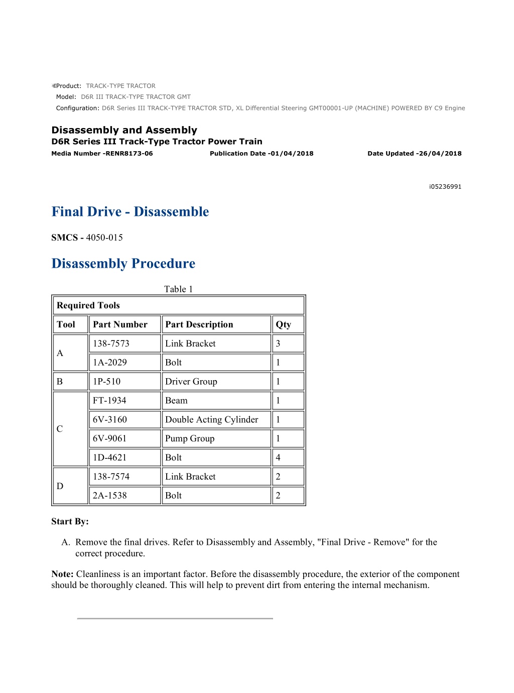
D6R Series III TRACK-TYPE TRACTOR STD, XL Differential Steering GMT00001... 1/6 Product: TRACK-TYPE TRACTOR Model: D6R III TRACK-TYPE TRACTOR GMT Configuration: D6R Series III TRACK-TYPE TRACTOR STD, XL Differential Steering GMT00001-UP (MACHINE) POWERED BY C9 Engine Disassembly and Assembly D6R Series III Track-Type Tractor Power Train Media Number -RENR8173-06 Publication Date -01/04/2018 Date Updated -26/04/2018 i05236991 Final Drive - Disassemble SMCS - 4050-015 Disassembly Procedure Table 1 Required Tools Tool Part Number Part Description Qty 138-7573 Link Bracket 3 A 1A-2029 Bolt 1 B 1P-510 Driver Group 1 FT-1934 Beam 1 6V-3160 Double Acting Cylinder 1 C 6V-9061 Pump Group 1 1D-4621 Bolt 4 138-7574 Link Bracket 2 D 2A-1538 Bolt 2 Start By: A. Remove the final drives. Refer to Disassembly and Assembly, "Final Drive - Remove" for the correct procedure. Note: Cleanliness is an important factor. Before the disassembly procedure, the exterior of the component should be thoroughly cleaned. This will help to prevent dirt from entering the internal mechanism. https://127.0.0.1/sisweb/sisweb/techdoc/techdoc_print_page.jsp?returnurl=/sis... 2021/3/15
D6R Series III TRACK-TYPE TRACTOR STD, XL Differential Steering GMT00001... 2/6 Illustration 1 g01195912 1. Install Tooling (A) and a suitable lifting device to planetary carrier (3) . 2. Remove bolts (1). Remove planetary carrier (3) and the two O-ring seals from the hub. The weight of planetary carrier (3) is approximately 137 kg (302 lb). 3. Remove retainers (2) . Illustration 2 g00841089 4. Place support under planetary carrier (3) in order to prevent damage. Use Tooling (B) and a suitable press to remove the planetary gear shafts. 5. Remove planetary gears (4) from planetary carrier (3) . https://127.0.0.1/sisweb/sisweb/techdoc/techdoc_print_page.jsp?returnurl=/sis... 2021/3/15
D6R Series III TRACK-TYPE TRACTOR STD, XL Differential Steering GMT00001... 3/6 Illustration 3 g00841091 6. Remove bearing cones (5) from gears (4) . 7. Remove the bearing cups from each side of the gears. Illustration 4 g00841092 Illustration 5 g01195913 8. Remove bolts (6) and retainer (7) . 9. Attach a suitable lifting device to hub (12) and ring gear (8). The weight of hub (12) and ring gear (8) is approximately 68 kg (150 lb). Remove hub (12) and ring gear (8) . https://127.0.0.1/sisweb/sisweb/techdoc/techdoc_print_page.jsp?returnurl=/sis... 2021/3/15
https://www.ebooklibonline.com Hello dear friend! Thank you very much for reading. Enter the link into your browser. The full manual is available for immediate download. https://www.ebooklibonline.com
D6R Series III TRACK-TYPE TRACTOR STD, XL Differential Steering GMT00001... 4/6 Illustration 6 g01195915 10. Turn over hub (9) and ring gear (8). Remove retaining ring (10). Attach a suitable lifting device to hub (9). The weight of hub (9) is approximately 37 kg (82 lb). The weight of ring gear (8) is approximately 32 kg (71 lb). Remove hub (9) . Illustration 7 g00841095 11. Install Tooling (C) on hub (12). Note: Do not lift hub (12) too high. Do not allow hub (12) to contact the fitting on the hydraulic cylinder. 12. Use Tooling (C) to loosen hub (12) from spindle (13). Remove Tooling (C) . 13. Remove bearing cone (11) . https://127.0.0.1/sisweb/sisweb/techdoc/techdoc_print_page.jsp?returnurl=/sis... 2021/3/15
D6R Series III TRACK-TYPE TRACTOR STD, XL Differential Steering GMT00001... 5/6 Illustration 8 g01195917 14. Install Tooling (D) and a suitable lifting device to hub (12). Remove hub (12) from spindle (13). The weight of hub (12) is approximately 180 kg (397 lb). Illustration 9 g00841099 15. Turn over hub (12). Remove Duo-Cone seal kit (15). Use a hammer and a punch to remove bearing cup (16) . 16. Turn over the hub. Remove bearing cup (14) from the hub. Note: If the Duo-Cone seal will be reused, mark the seal kits for installation purposes. https://127.0.0.1/sisweb/sisweb/techdoc/techdoc_print_page.jsp?returnurl=/sis... 2021/3/15
D6R Series III TRACK-TYPE TRACTOR STD, XL Differential Steering GMT00001... 6/6 Illustration 10 g00841101 Note: Bearing cone (18) may be damaged if the bearing cone is removed from spindle (13) . 17. Remove Duo-Cone seal (19) from spindle (13) . 18. If necessary, remove bearing cone (18) from the spindle. 19. Remove lip seal (17) from spindle (13) . https://127.0.0.1/sisweb/sisweb/techdoc/techdoc_print_page.jsp?returnurl=/sis... 2021/3/15
D6R Series III TRACK-TYPE TRACTOR STD, XL Differential Steering GMT00001... 1/6 Product: TRACK-TYPE TRACTOR Model: D6R III TRACK-TYPE TRACTOR GMT Configuration: D6R Series III TRACK-TYPE TRACTOR STD, XL Differential Steering GMT00001-UP (MACHINE) POWERED BY C9 Engine Disassembly and Assembly D6R Series III Track-Type Tractor Power Train Media Number -RENR8173-06 Publication Date -01/04/2018 Date Updated -26/04/2018 i06701251 Final Drive - Assemble SMCS - 4050-016 Assembly Procedure Table 1 Required Tools Tool Part Number Part Description Qty 138-7573 Link Bracket 3 A 1A-2029 Bolt 3 B 1P-0520 Driver Gp 1 138-7574 Link Bracket 2 D 2A-1538 Bolt 2 E 8M-9395 Installer 1 1. Apply clean oil to all the parts during assembly. https://127.0.0.1/sisweb/sisweb/techdoc/techdoc_print_page.jsp?returnurl=/sis... 2021/3/15
D6R Series III TRACK-TYPE TRACTOR STD, XL Differential Steering GMT00001... 2/6 Illustration 1 g06081205 2. Use Tooling (B) to install lip seal (17) in spindle (13) to a depth of (X) 9 0.25 mm (0.3543 0.0098 inch). Put clean oil on the lip of the seal. Note: Dimension (X) is measured from the face of the spindle to the top of the metal can of the lip seal in the orientation shown. Note: Do not apply excessive force to lip seal (17) during installation to avoid damaging the seal. Illustration 2 g00841209 3. Raise the temperature of bearing cone (18) to a maximum temperature of 135 C (275 F). Install bearing cone (18) on spindle (13). Note: Before the installation of the Duo-Cone seal, refer to Disassembly and Assembly, "Duo-Cone Floating Seals - Install" for the correct procedure. 4. Use Tooling (E) to install the Duo-Cone seal on spindle (13). https://127.0.0.1/sisweb/sisweb/techdoc/techdoc_print_page.jsp?returnurl=/sis... 2021/3/15
D6R Series III TRACK-TYPE TRACTOR STD, XL Differential Steering GMT00001... 3/6 Illustration 3 g00841210 5. Lower the temperature of bearing cups (14) and (16). Install bearing cups (14) and (16) in hub (12). 6. Use Tooling (E) to install the Duo-Cone seal in hub (12). Illustration 4 g01195917 7. Install Tooling (D) on hub (12). Attach a suitable lifting device to Tooling (D). Carefully position hub (12) on spindle (13). Illustration 5 g00841212 8. Raise the temperature of bearing cone (11). Install bearing cone (11) on spindle (13). https://127.0.0.1/sisweb/sisweb/techdoc/techdoc_print_page.jsp?returnurl=/sis... 2021/3/15
D6R Series III TRACK-TYPE TRACTOR STD, XL Differential Steering GMT00001... 4/6 Illustration 6 g01195915 9. Attach a suitable lifting device to hub (9) and position hub (9) in ring gear (8). Install retaining ring (10). Illustration 7 g01195913 10. Turn over the hub (9) and ring gear (8). Attach a suitable lifting device to hub (9) and the ring gear (8) into position in hub (12). Illustration 8 g00841092 11. Put retainer (7) into position. Install bolts (6) while the hub is slowly rotated. Tighten bolts (6) evenly to a torque of 135 15 N m (100 11 lb ft). The retainer must contact the end of spindle (13) after bolts (6) have been tightened. https://127.0.0.1/sisweb/sisweb/techdoc/techdoc_print_page.jsp?returnurl=/sis... 2021/3/15
D6R Series III TRACK-TYPE TRACTOR STD, XL Differential Steering GMT00001... 5/6 Illustration 9 g00841213 12. Lower the temperature of bearing cups (20) and (21). Install the bearing cups in three planetary gears (4). Illustration 10 g00841215 Illustration 11 g00841216 13. Position the planetary carrier in a press. The shaft (22) must be in position with proper support to be a positive stop for the shaft. https://127.0.0.1/sisweb/sisweb/techdoc/techdoc_print_page.jsp?returnurl=/sis... 2021/3/15
D6R Series III TRACK-TYPE TRACTOR STD, XL Differential Steering GMT00001... 6/6 NOTICE The shaft must be correctly installed. If the shaft is incorrectly installed, the bearing preload will be incorrect. This will result in component damage. 14. Position planetary gear (4) in the planetary carrier. 15. Lower the temperature of shaft (22). Use a suitable press to install the shaft in the planetary carrier. After the installation, the end of shaft (22) must be flush with the retainer of the planetary carrier. This will provide the correct bearing preload. The gear must rotate by hand after installation. If the gear does not rotate, the problem must be corrected. Repeat this procedure for all three shafts. Illustration 12 g01195912 16. Install three retainers (2) on shafts (22). 17. Install Tooling (A). Attach a suitable lifting device to Tooling (A). Install the two O-ring seals on the planetary carrier. Align the drain hole in the planetary carrier with the drain hole in the hub. 18. Position the planetary carrier in the hub. 19. Install bolts (1) that hold planetary carrier (3) to the hub. Remove Tooling (A). End By: a. Install the final drives. Refer to Disassembly and Assembly, "Final Drive - Install" for the correct procedure. https://127.0.0.1/sisweb/sisweb/techdoc/techdoc_print_page.jsp?returnurl=/sis... 2021/3/15
D6R Series III TRACK-TYPE TRACTOR STD, XL Differential Steering GMT00001... 1/4 Product: TRACK-TYPE TRACTOR Model: D6R III TRACK-TYPE TRACTOR GMT Configuration: D6R Series III TRACK-TYPE TRACTOR STD, XL Differential Steering GMT00001-UP (MACHINE) POWERED BY C9 Engine Disassembly and Assembly D6R Series III Track-Type Tractor Power Train Media Number -RENR8173-06 Publication Date -01/04/2018 Date Updated -26/04/2018 i03576221 Final Drive - Install SMCS - 4050-012 Installation Procedure Table 1 Required Tools Tool Part Number Part Description Qty A FT-1952 Installer 1 8T-3207 Lifting Bracket 1 5P-8622 Shackle 1 B 1D-4593 5/8 - 11 by 5 1/2 bolt 2 4K-0367 5/8 - 11 by nut 2 5P-8248 Washer 4 Illustration 1 g00826743 1. Adjust the top bracket of Tooling (B) until Dimension (X) is 222.25 mm (8.750 inch). Attach Tooling (B) to the final drive. https://127.0.0.1/sisweb/sisweb/techdoc/techdoc_print_page.jsp?returnurl=/sis... 2021/3/15
D6R Series III TRACK-TYPE TRACTOR STD, XL Differential Steering GMT00001... 2/4 Illustration 2 g00865095 2. Use Tooling (B) to install final drive (1). The weight of final drive (1) is approximately 454 kg (1000 lb). Illustration 3 g00865094 3. Install bolts (7) that hold the final drive and the steering clutch and brake together. Tighten bolts (7) to a torque of 700 90 N m (516 66 lb ft). Illustration 4 g00865082 4. Remove Tooling (B) from the final drive. https://127.0.0.1/sisweb/sisweb/techdoc/techdoc_print_page.jsp?returnurl=/sis... 2021/3/15
D6R Series III TRACK-TYPE TRACTOR STD, XL Differential Steering GMT00001... 3/4 Illustration 5 g00865077 5. Install two bolts (6) to the sprocket segment. Illustration 6 g00865075 6. Install two bolts (5). Illustration 7 g00865024 7. Use Tooling (A) to install axle (4). Remove Tooling (A). Note: Carefully install the axle shaft (4) into the final drive (1). It is possible that the axle shaft (4) could damage the lip seal. https://127.0.0.1/sisweb/sisweb/techdoc/techdoc_print_page.jsp?returnurl=/sis... 2021/3/15
D6R Series III TRACK-TYPE TRACTOR STD, XL Differential Steering GMT00001... 4/4 Illustration 8 g00865052 8. Install cover (3) and bolts (2) on final drive (1). End By: a. Connect the track. Refer to Disassembly and Assembly, "Track - Connect". https://127.0.0.1/sisweb/sisweb/techdoc/techdoc_print_page.jsp?returnurl=/sis... 2021/3/15
D6R Series III TRACK-TYPE TRACTOR STD, XL Differential Steering GMT00001... 1/5 Product: TRACK-TYPE TRACTOR Model: D6R III TRACK-TYPE TRACTOR GMT Configuration: D6R Series III TRACK-TYPE TRACTOR STD, XL Differential Steering GMT00001-UP (MACHINE) POWERED BY C9 Engine Disassembly and Assembly D6R Series III Track-Type Tractor Power Train Media Number -RENR8173-06 Publication Date -01/04/2018 Date Updated -26/04/2018 i02553052 Final Drive, Steering Differential, and Brake (Left Side) - Remove SMCS - 4050-011-LT; 4131-011 Removal Procedure Table 1 Required Tools Tool Part Number Part Description Qty A 5B-4274 (3/8 - 16 NC - 3 1/2) 3 B 8T-3207 Lifting Bracket 1 C 138-7575 Link Bracket 1 D 8S-9906 Ratchet Puller 1 Start By: a. Separate the track. Refer to Disassembly and Assembly, "Track - Separate". b. Remove the axles. Refer to Disassembly and Assembly, "Axle - Remove and Install". c. Remove the steering motor. Refer to Disassembly and Assembly, "Steering Motor - Remove". Note: Cleanliness is an important factor. Before the disassembly procedure, the exterior of the component should be thoroughly cleaned. This will help to prevent dirt from entering the internal mechanism. NOTICE Care must be taken to ensure that fluids are contained during performance of inspection, maintenance, testing, adjusting, and repair of the product. Be prepared to collect the fluid with suitable containers before opening any compartment or disassembling any component containing fluids. https://127.0.0.1/sisweb/sisweb/techdoc/techdoc_print_page.jsp?returnurl=/sis... 2021/3/15
D6R Series III TRACK-TYPE TRACTOR STD, XL Differential Steering GMT00001... 2/5 Refer to Special Publication, NENG2500, "Dealer Service Tool Catalog" for tools and supplies suitable to collect and contain fluids on Cat products. Dispose of all fluids according to local regulations and mandates. Personal injury can result from hydraulic oil pressure and hot oil. Hydraulic oil pressure can remain in the hydraulic system after the engine has been stopped. Serious injury can be caused if this pressure is not released before any service is done on the hydraulic system. Make sure all of the work tools have been lowered to the ground, and the oil is cool before removing any components or lines. Remove the oil filler cap only when the engine is stopped, and the filler cap is cool enough to touch with your bare hand. 1. Drain the hydraulic oil from the hydraulic system into a suitable container for storage or disposal. 2. Remove the floorplate. 3. Remove the plate under the seat. Illustration 1 g01202478 4. Remove bolts (1). https://127.0.0.1/sisweb/sisweb/techdoc/techdoc_print_page.jsp?returnurl=/sis... 2021/3/15
D6R Series III TRACK-TYPE TRACTOR STD, XL Differential Steering GMT00001... 3/5 Illustration 2 g01202481 5. Install Tooling (A) and remove housing (2). Illustration 3 g01202482 6. Remove bolt (3) from hand rail (4). Position hand rail (4) out of the way. This will allow more room for Tooling (B). Illustration 4 g01202483 https://127.0.0.1/sisweb/sisweb/techdoc/techdoc_print_page.jsp?returnurl=/sis... 2021/3/15
D6R Series III TRACK-TYPE TRACTOR STD, XL Differential Steering GMT00001... 4/5 Illustration 5 g01202485 7. Remove bolts (5). Do not remove bolt (6) and install Tooling (C). Remove two bolts (7). 8. Remove two bolts from the top of the sprocket segment. Install Tooling (B). Adjust the hook of Tooling (B) to the maximum length. 9. Remove the bolts and washers (5). Remove the bolt and washer (7). Do not remove bolt (6). Illustration 6 g00870958 10. Attach Tooling (D) to Tooling (C) and Tooling (B). 11. Remove the remaining bolts (5). Separate the final drive approximately 152 mm (6.0 inch). 12. Release the pressure on Tooling (D). Rotate brake housing 90 degrees in the counterclockwise direction. Illustration 7 g01202489 https://127.0.0.1/sisweb/sisweb/techdoc/techdoc_print_page.jsp?returnurl=/sis... 2021/3/15
D6R Series III TRACK-TYPE TRACTOR STD, XL Differential Steering GMT00001... 5/5 13. Rotating the brake housing allows pinion (8) to point forward. Rotating the brake housing will allow the final drive to swing toward the front of the machine. Rotating the brake housing will allow clearance for the ring gear to clear the machine. The weight of the final drive assembly is approximately 680 kg (1500 lb). https://127.0.0.1/sisweb/sisweb/techdoc/techdoc_print_page.jsp?returnurl=/sis... 2021/3/15
D6R Series III TRACK-TYPE TRACTOR STD, XL Differential Steering GMT00001... 1/17 Product: TRACK-TYPE TRACTOR Model: D6R III TRACK-TYPE TRACTOR GMT Configuration: D6R Series III TRACK-TYPE TRACTOR STD, XL Differential Steering GMT00001-UP (MACHINE) POWERED BY C9 Engine Disassembly and Assembly D6R Series III Track-Type Tractor Power Train Media Number -RENR8173-06 Publication Date -01/04/2018 Date Updated -26/04/2018 i06983834 Steering Differential and Brake - Disassemble SMCS - 4131-015 Disassembly Procedure Table 1 Required Tools Tool Part Number Description Qty A 138-7573 Link Bracket 2 B 3K-4897 Spring Pin 8 C 6V-4072 Spanner Wrench 1 9S-9154 Step Plate 1 6V-3009 Bar 1 8S-6470 Forcing Screw 3/4 inch - 16 by 4 inch 1 D 8S-5133 Plug 1 5P-8245 Washer 4 1D-4719 Nut 1/2 inch - 13 2 2H-6488 Bolt 1/2 inch - 13 by 5 inch 2 E 9S-9154 Step Plate 1 6V-3009 Bar 1 8S-6470 Forcing Screw 3/4 inch - 16 by 4 inch 1 8S-5133 Plug 1 5P-8245 Washer 4 1D-4719 Nut 1/2 inch - 13 2 1D-4574 Bolt 1/2 inch - 13 by 6 inch 2 https://127.0.0.1/sisweb/sisweb/techdoc/techdoc_print_page.jsp?returnurl=/sis... 2021/3/15
D6R Series III TRACK-TYPE TRACTOR STD, XL Differential Steering GMT00001... 2/17 8H-0663 Bearing Puller 1 F 138-7575 Link Bracket 3 8B-7550 Leg 2 8B-7559 Adapter 2 3H-0465 Plate 4 1P-0498 Plate 1 1B-4207 Nut 3/4 inch - 16 2 G 5H-9976 Forcing Screw 1 inch - 14 by 5 3/4 inch 1 5B-0637 Nut 1 inch - 14 1 8H-0684 Ratchet Wrench 1 8B-7563 Handle 1 5F-7353 Washer (Thrust) 1 8B-7548 Push-Puller Tool Gp 1 Start By: a. Remove the left final drive, the steering differential, and the brake. Refer to Disassembly and Assembly, "Final Drive, Steering Differential, and Brake (Left Side) - Remove" . Illustration 1 g00823680 https://127.0.0.1/sisweb/sisweb/techdoc/techdoc_print_page.jsp?returnurl=/sis... 2021/3/15
D6R Series III TRACK-TYPE TRACTOR STD, XL Differential Steering GMT00001... 3/17 1. Remove bolts (1) and washers. 2. Remove two opposite bolts (2). Illustration 2 g00823691 3. Attach Tooling (A) and a suitable lifting device. 4. Remove sliding carrier (3). The weight of sliding carrier (3) is approximately 48 kg (105 lb). 5. Remove Tooling (A). https://127.0.0.1/sisweb/sisweb/techdoc/techdoc_print_page.jsp?returnurl=/sis... 2021/3/15
D6R Series III TRACK-TYPE TRACTOR STD, XL Differential Steering GMT00001... 4/17 Illustration 3 g06187075 6. Remove remaining bolts (2) and slinger (4) from planetary carrier (7). 7. Remove retaining ring (5), thrust ring (5A), and planetary carrier (7) from ring gear (6). Illustration 4 g00823775 8. Remove seal ring (10) from planetary carrier (7). 9. Use a hammer and a punch to push pin (12) in shaft (11). 10. Remove shaft (11), planetary gear (9), discs (8), and bearing (13) from planetary carrier (7). 11. Remove pin (12) from shaft (11). 12. Repeat Steps 9 through 11 for the remaining planetary gears. https://127.0.0.1/sisweb/sisweb/techdoc/techdoc_print_page.jsp?returnurl=/sis... 2021/3/15
D6R Series III TRACK-TYPE TRACTOR STD, XL Differential Steering GMT00001... 5/17 Illustration 5 g00823759 13. Remove lockring (14) and remove retaining ring (16). 14. Remove sun gear (15) from planetary carrier (18). 15. Remove spacer (17). https://127.0.0.1/sisweb/sisweb/techdoc/techdoc_print_page.jsp?returnurl=/sis... 2021/3/15
D6R Series III TRACK-TYPE TRACTOR STD, XL Differential Steering GMT00001... 6/17 Illustration 6 g00823816 16. Remove bolts (19), plate (20), and gear (21) from planetary carrier (18). 17. Use Tooling (B) to compress the retaining ring that holds planetary carrier (18) in ring gear (6). 18. Separate planetary carrier (18) from ring gear (6). 19. Remove the retaining ring from planetary carrier (18). 20. Use a hammer and a punch to push pin (23) in shaft (24). https://127.0.0.1/sisweb/sisweb/techdoc/techdoc_print_page.jsp?returnurl=/sis... 2021/3/15
D6R Series III TRACK-TYPE TRACTOR STD, XL Differential Steering GMT00001... 7/17 Illustration 7 g00823872 21. Remove shaft (24), planetary gear (22), discs (26), and bearing (25) from planetary carrier (18). 22. Remove pin (23) from shaft (24). 23. Repeat Steps 20 through 22 for the remaining planetary gears. https://127.0.0.1/sisweb/sisweb/techdoc/techdoc_print_page.jsp?returnurl=/sis... 2021/3/15
Suggest: If the above button click is invalid. Please download this document first, and then click the above link to download the complete manual. Thank you so much for reading
D6R Series III TRACK-TYPE TRACTOR STD, XL Differential Steering GMT00001... 8/17 Illustration 8 g00823878 24. Place a bolt in the teeth of bevel pinion (27) to prevent movement. https://127.0.0.1/sisweb/sisweb/techdoc/techdoc_print_page.jsp?returnurl=/sis... 2021/3/15
https://www.ebooklibonline.com Hello dear friend! Thank you very much for reading. Enter the link into your browser. The full manual is available for immediate download. https://www.ebooklibonline.com