Caterpillar Cat 311 TRACK-TYPE EXCAVATOR (Prefix 9LJ) Service Repair Manual Instant Download
Please open the website below to get the complete manualnn//

Download Presentation
Please find below an Image/Link to download the presentation.
The content on the website is provided AS IS for your information and personal use only. It may not be sold, licensed, or shared on other websites without obtaining consent from the author. Download presentation by click this link. If you encounter any issues during the download, it is possible that the publisher has removed the file from their server.
Presentation Transcript
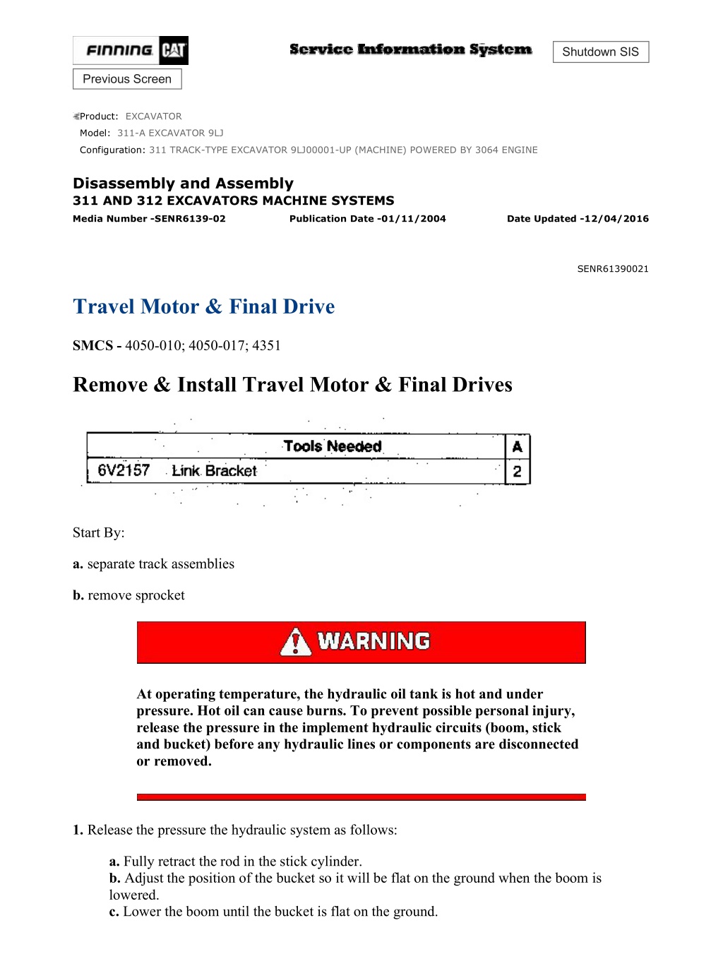
311 TRACK-TYPE EXCAVATOR 9LJ00001-UP (MACHINE) POWERED BY 3064... 1/46 Shutdown SIS Previous Screen Product: EXCAVATOR Model: 311-A EXCAVATOR 9LJ Configuration: 311 TRACK-TYPE EXCAVATOR 9LJ00001-UP (MACHINE) POWERED BY 3064 ENGINE Disassembly and Assembly 311 AND 312 EXCAVATORS MACHINE SYSTEMS Media Number -SENR6139-02 Publication Date -01/11/2004 Date Updated -12/04/2016 SENR61390021 Travel Motor & Final Drive SMCS - 4050-010; 4050-017; 4351 Remove & Install Travel Motor & Final Drives Start By: a. separate track assemblies b. remove sprocket At operating temperature, the hydraulic oil tank is hot and under pressure. Hot oil can cause burns. To prevent possible personal injury, release the pressure in the implement hydraulic circuits (boom, stick and bucket) before any hydraulic lines or components are disconnected or removed. 1. Release the pressure the hydraulic system as follows: a. Fully retract the rod in the stick cylinder. b. Adjust the position of the bucket so it will be flat on the ground when the boom is lowered. c. Lower the boom until the bucket is flat on the ground. https://127.0.0.1/sisweb/sisweb/techdoc/techdoc_print_page.jsp?returnurl=/sis... 2021/2/11
311 TRACK-TYPE EXCAVATOR 9LJ00001-UP (MACHINE) POWERED BY 3064... 2/46 d. Shut off the engine, and put the hydraulic activation control lever in the "LOCK" position. e. Move the control levers for the boom, bucket, stick and swing through their full travel strokes. This will relieve any pressure that may be present in the pilot system. f. Slowly loosen the air breather cap on the hydraulic oil tank to release the pressure. g. Tighten the air breather cap on the hydraulic oil tank. h. The pressure in the hydraulic system has now been released. Lines and components can now be removed. 2. Remove access cover assembly (1) from over the rear side of the final drive. 3. Disconnect hose assemblies (2) and (3) from the travel motor. Put plugs in the hose assemblies to keep dirt and debris out of the hydraulic system. 4. Fasten tool (A) and a hoist to final drive. Put slight lifting tension on the final drive with the hoist. 5. Remove sixteen bolts (4) that hold the travel motor and the final drive to the undercarriage frame assembly. Remove the travel motor and final drive. The weight of the travel motor and the final drive is 160 kg (352 lb). NOTE: The following steps are for the installation of the final drive. 6. Be sure the mating surfaces of the final drive and the undercarriage frame assembly are clean and free of dirt and debris. https://127.0.0.1/sisweb/sisweb/techdoc/techdoc_print_page.jsp?returnurl=/sis... 2021/2/11
311 TRACK-TYPE EXCAVATOR 9LJ00001-UP (MACHINE) POWERED BY 3064... 3/46 7. Check the condition of the O-ring seals in the ends of hose assemblies (2) and (3). If any of the seals are worn or damaged, use new parts for replacement. 8. Fasten tool (A) and a hoist to travel motor and final drive and put it in position in the undercarriage frame assembly. Be sure all mounting bolt holes are in alignment. 9. Put a thin coat of 9S3263 Thread Lock on threads of sixteen bolts (4). Install sixteen bolts (4) that hold the final drive to the undercarriage frame assembly. Tighten the bolts evenly. 10. Connect hose assemblies (2) and (3) to the travel motor. 11. Reinstall the access cover assembly over the rear of the final drive. 12. Check the oil level in the hydraulic tank. If necessary, fill it to the correct level. See the Operation & Maintenance Manual for the correct filling procedure. End By: a. install sprocket b. connect track assemblies Disassemble & Assemble Travel Motor & Final Drives (312 Excavator) Start By: a. remove travel motor and final drive 1. Thoroughly clean the outside of the travel motor and the final drive prior to disassembly. 2. Put an alignment mark across the sections of the travel motor and the final drive for assembly purposes. The parts must be reinstalled in their original locations. https://127.0.0.1/sisweb/sisweb/techdoc/techdoc_print_page.jsp?returnurl=/sis... 2021/2/11
https://www.ebooklibonline.com Hello dear friend! Thank you very much for reading. Enter the link into your browser. The full manual is available for immediate download. https://www.ebooklibonline.com
311 TRACK-TYPE EXCAVATOR 9LJ00001-UP (MACHINE) POWERED BY 3064... 4/46 3. Fasten the travel motor and the final drive to tool (A) as shown. Remove the drain plug to drain the oil. The capacity of the final drive is 2.5 liters (.6 U.S. gal). 4. Remove ten bolts (1) and travel brake valve (2). 5. Position travel brake valve (2) on wood blocks as shown. Remove relief valve (3). 6. Remove back-up rings (4), O-ring seal (5), O-ring seal (6) and back-up ring (7) from the relief valve. There is spring pressure behind cap (9) which may cause the assembly to fly apart when cap mounting bolts (8) are removed. To prevent possible personal injury, remove only two cap mounting bolts (8) that https://127.0.0.1/sisweb/sisweb/techdoc/techdoc_print_page.jsp?returnurl=/sis... 2021/2/11
311 TRACK-TYPE EXCAVATOR 9LJ00001-UP (MACHINE) POWERED BY 3064... 5/46 are diagonal to each other. Then, alternating between the two remaining cap mounting bolts, slowly loosen them a small amount at a time, until the spring pressure is completely released. 7. Remove two cap mounting bolts (8) that are diagonal to each other. Then, alternating between the two remaining cap mounting bolts, slowly loosen them a small amount at a time, until the spring pressure is released. Remove cap (9) from the travel brake valve. NOTE: Spool assembly (12) should not be disassembled. That component is serviced as an assembly. 8. Remove spring (10), washer (11) and spool assembly (12) from the travel brake valve. 9. Remove plug (13) and O-ring seal (14) from the travel brake valve. Remove the O-ring seal from plug (13). 10. Remove plunger (15) and spring (16) located behind plug (13), from the travel brake valve. https://127.0.0.1/sisweb/sisweb/techdoc/techdoc_print_page.jsp?returnurl=/sis... 2021/2/11
311 TRACK-TYPE EXCAVATOR 9LJ00001-UP (MACHINE) POWERED BY 3064... 6/46 11. Remove two plugs (17). 12. Remove O-ring seal (18) from each plug. Remove ball (19) from the travel brake valve. 13. Remove three hose fittings (20). Remove all of the O-ring seals from hose fittings (20). 14. Remove plug (21) from the travel brake valve. Remove the O-ring seal from plug (21). https://127.0.0.1/sisweb/sisweb/techdoc/techdoc_print_page.jsp?returnurl=/sis... 2021/2/11
311 TRACK-TYPE EXCAVATOR 9LJ00001-UP (MACHINE) POWERED BY 3064... 7/46 15. Remove four cap mounting bolts (22) and remove cap (23). Remove fitting (24). Remove the O-ring seal from fitting (24). 16. Remove spring (25) and washer (26) from the travel brake valve. Remove O-ring seal (27) from the valve body. 17. Remove relief valve (28) from the valve body. 18. Remove back-up rings (29), O-ring seal (30), O-ring seal (31) and back-up ring (32) from the relief valve. 19. Reposition the travel brake valve body as shown. Remove plate (33) from the body. https://127.0.0.1/sisweb/sisweb/techdoc/techdoc_print_page.jsp?returnurl=/sis... 2021/2/11
311 TRACK-TYPE EXCAVATOR 9LJ00001-UP (MACHINE) POWERED BY 3064... 8/46 20. If necessary, remove bearing (34) and location pin (35). 21. Remove three O-ring seals (36) and washer set (37) from the travel motor body. 22. Remove shim (38). 23. Install tooling (B) as shown. While retaining brake piston (39) with tooling (B), apply shop air pressure (free of water) of approximately 525 kPa (75 psi) to brake release port (Y). Brake piston (39) will move up and out of the travel motor body. Remove brake piston (39) from the travel motor body. https://127.0.0.1/sisweb/sisweb/techdoc/techdoc_print_page.jsp?returnurl=/sis... 2021/2/11
311 TRACK-TYPE EXCAVATOR 9LJ00001-UP (MACHINE) POWERED BY 3064... 9/46 24. Remove O-ring seals (40) and (42) and back-up rings (41) and (43) from the brake piston. 25. Remove two friction plates and two steel plates (44) from the travel motor body. NOTICE Do not let the components of barrel assembly (45) come apart during the removal from the travel motor body. All components in the barrel assembly must be reinstalled in their original locations. 26. Fasten tooling (C) and position the travel motor and the final drive as shown. Remove barrel assembly (45) from the travel motor body. https://127.0.0.1/sisweb/sisweb/techdoc/techdoc_print_page.jsp?returnurl=/sis... 2021/2/11
311 TRACK-TYPE EXCAVATOR 9LJ00001-UP (MACHINE) POWERED BY 30... 10/46 27. Shoe retainer (46) and piston shoe assemblies (47) are not serviced separately. Prior to removal of the shoe retainer and the piston shoe assemblies from barrel (48), put identification marks on piston shoe assemblies (47) as to their location in shoe retainer (46) and barrel (48). The piston shoe assemblies must be reinstalled in their original bores in the shoe retainer and the barrel. 28. Remove shoe retainer (46) and piston shoe assemblies (47) from barrel (48). Separate the piston shoe assemblies from the shoe retainer. 29. Remove bushing (49) from the barrel. 30. Remove three pins (50) from the barrel. https://127.0.0.1/sisweb/sisweb/techdoc/techdoc_print_page.jsp?returnurl=/sis... 2021/2/11
311 TRACK-TYPE EXCAVATOR 9LJ00001-UP (MACHINE) POWERED BY 30... 11/46 There is spring force against washer (52). When snap ring (51) is removed, the spring force will be released. To prevent possible personal injury, removal of the internal components in barrel (48) should be performed in a press in order to retain spring (53) and washer (52). 31. Put barrel (48) in a press. Install a suitable size drive plate that is slightly smaller in diameter than washer (52), on washer (52). Put a slight amount of compression on washer (52) with the press. Remove snap ring (51) and slowly release the spring compression. Remove washer (52), spring (53) and washer (54) from the barrel (48). 32. Remove cam plate (55) from the travel motor body. 33. Put identification marks on two balls (56) and piston (57) as to their location in the travel motor body. Remove two balls (56) and piston (57) from the travel motor body. Remove the spring located behind the piston. 34. Fasten the final drive to tool (A) as shown. Remove sixteen bolts (58) and the washers that hold cover (59) in place. 35. Using a soft faced hammer, break the seal between cover (59) and ring gear (60). Remove the cover. https://127.0.0.1/sisweb/sisweb/techdoc/techdoc_print_page.jsp?returnurl=/sis... 2021/2/11
311 TRACK-TYPE EXCAVATOR 9LJ00001-UP (MACHINE) POWERED BY 30... 12/46 36. Remove washer (61) and three bolts (62) and plate (63). 37. Remove sun gear (64) from the carrier assembly. 38. Remove carrier assembly (65) by lifting it straight up. 39. Remove planetary gear (66) and bearing (67) from the carrier assembly. If necessary, remove race (68) from the carrier assembly shaft. 40. Remove the other two planetary gears from the carrier assembly as in Step 39. https://127.0.0.1/sisweb/sisweb/techdoc/techdoc_print_page.jsp?returnurl=/sis... 2021/2/11
311 TRACK-TYPE EXCAVATOR 9LJ00001-UP (MACHINE) POWERED BY 30... 13/46 41. Remove sun gear (69) from carrier assembly (70). Remove retaining ring (71) from sun gear (68). 43. Remove four bolts (72) and plate (73). 44. Remove planetary gear (74), bearing (75), race (76) and washer (77) from the carrier assembly. 45. Remove the other three planetary gears from the carrier assembly as in Step 44. https://127.0.0.1/sisweb/sisweb/techdoc/techdoc_print_page.jsp?returnurl=/sis... 2021/2/11
311 TRACK-TYPE EXCAVATOR 9LJ00001-UP (MACHINE) POWERED BY 30... 14/46 46. Remove bolt (78) from the planetary carrier. 47. Use a magnet to remove pin (79). 48. Remove nut (80) from the final drive housing. 49. Fasten tool (C) and a hoist to ring gear (60) as shown. Remove the ring gear from the main housing. https://127.0.0.1/sisweb/sisweb/techdoc/techdoc_print_page.jsp?returnurl=/sis... 2021/2/11
311 TRACK-TYPE EXCAVATOR 9LJ00001-UP (MACHINE) POWERED BY 30... 15/46 50. Remove bearing (81) from the ring gear. 51. If necessary, remove race (82) from the ring gear. 52. Reposition the ring gear as shown. If necessary, remove race (83) from the ring gear. 53. Remove Duo-Cone seal (84) from the main housing. 54. Remove bearing (85) from the main housing. https://127.0.0.1/sisweb/sisweb/techdoc/techdoc_print_page.jsp?returnurl=/sis... 2021/2/11
311 TRACK-TYPE EXCAVATOR 9LJ00001-UP (MACHINE) POWERED BY 30... 16/46 55. Remove Duo-Cone seal (86) from main housing (87). 56. Reposition the main housing as shown. Remove shaft (88) from the main housing. Remove bearing (89) from the shaft. NOTE: The following steps are for the assembly of the travel motor and the final drive. 57. Be sure all of the travel motor and final drive are thoroughly clean and free of dirt and debris prior to assembly. Check the condition of all O-ring seals used in the travel motor and final drive. If any of the seals are worn or damaged, use new parts for replacement. Reassemble the travel motor and final drive on tool (A). 58. Put bearing (89) on shaft (88). Install shaft (88) into the main housing. NOTICE See the topic "Assembly And Installation Of Conventional Duo-Cone Seals" in this module. NOTE: The rubber seals and all of the surfaces that make contact with the seals must be clean and dry. After the installation of the seals, put clean SAE 30 oil on the contact surfaces of the metal seals. https://127.0.0.1/sisweb/sisweb/techdoc/techdoc_print_page.jsp?returnurl=/sis... 2021/2/11
311 TRACK-TYPE EXCAVATOR 9LJ00001-UP (MACHINE) POWERED BY 30... 17/46 59. Using tool (D), install Duo-Cone seal (86) in the main housing. 60. Install bearing (85) on the main housing. 61. Install race (83) to the ring gear. 62. Install race (82) to the ring gear. 63. Install bearing (81) to the ring gear. NOTICE See the topic "Assembly And Installation Of Conventional Duo-Cone Seals" in this module. https://127.0.0.1/sisweb/sisweb/techdoc/techdoc_print_page.jsp?returnurl=/sis... 2021/2/11
311 TRACK-TYPE EXCAVATOR 9LJ00001-UP (MACHINE) POWERED BY 30... 18/46 NOTE: The rubber seals and all of the surfaces that make contact with the seals must be clean and dry. After the installation of the seals, put clean SAE 30 oil on the contact surfaces of the metal seals. 64. Using tool (D), install Duo-Cone seal (84) in the main housing. Do not scratch or damage the Duo-Cone seals in the main housing or the ring gear during assembly of these two components. After the installation of the ring gear on the main housing, there will be a small gap between the components. The gap is caused by the Duo-Cone seals and will be eliminated during the installation of nut (80). 65. Fasten tool (C) and a hoist to ring gear (60) as shown. Install the ring gear on the main housing. 66. Use the following procedure to make a preload adjustment of bearing (81) as follows: a. Tighten nut (80) until there is no gap between main housing (87) and bearing (81). b. Rotate ring gear (60) several turns. https://127.0.0.1/sisweb/sisweb/techdoc/techdoc_print_page.jsp?returnurl=/sis... 2021/2/11
311 TRACK-TYPE EXCAVATOR 9LJ00001-UP (MACHINE) POWERED BY 30... 19/46 c. Turn nut (80) in and/or out until rotational torque of the ring gear (60) is 46 7 N m (34 5 lb ft). For serial number 6GK1-1450, turn nut (80) in and/or out until rotational torque of the ring gear (60) is 21 5 N m (15 4 lb ft). 67. Install pin (79) in nut (80). 68. Apply 9S3263 Thread Lock to bolt (78). Install bolt (78) to the planetary carrier. Tighten the bolt to a torque of 69 5 N m (50 4 lb ft). 69. Position the travel motor and the final drive housing as shown. Install two balls (56), the spring and piston (57) in the travel motor body. 70. Install cam plate (55) in the travel motor body. Be sure the machined cutouts in the cam plate engage with the balls and piston. https://127.0.0.1/sisweb/sisweb/techdoc/techdoc_print_page.jsp?returnurl=/sis... 2021/2/11
311 TRACK-TYPE EXCAVATOR 9LJ00001-UP (MACHINE) POWERED BY 30... 20/46 71. Install washer (54), spring (53) and washer (52) in barrel (48). 72. Use a press, and compress spring (53). Install retaining ring (51). 73. Install three pins (50) in the barrel. 74. Install bushing (49) to the barrel. 75. Install piston shoe assemblies (47) in their original bores in shoe retainer (46). https://127.0.0.1/sisweb/sisweb/techdoc/techdoc_print_page.jsp?returnurl=/sis... 2021/2/11
311 TRACK-TYPE EXCAVATOR 9LJ00001-UP (MACHINE) POWERED BY 30... 21/46 76. Put clean hydraulic oil in the bores of the barrel and on piston shoe assemblies (47). Install the piston shoe assemblies with the shoe retainer in their original bores in barrel (48). 77. Put clean hydraulic oil on the sliding surfaces of the cam plate, the piston shoe assemblies and on the splined shaft of the motor. Put the travel motor body on its side and install barrel assembly (45) on the shaft as a unit. 78. Put clean hydraulic oil on two friction plates and two steel plates (44). Install the plates in alternating order in the travel motor body. Start with a friction plate and end with a steel plate. 79. Be sure brake piston (39) is thoroughly clean and free of dirt and debris. Check the condition of back-up rings (41) and (43) and O-ring seals (40) and (42). If the rings or the seals are worn or damaged, use new parts for replacement. Install back-up rings (41) and (43) and O-ring seals (40) and (42) on brake piston (39) as shown. Put a coat of 1U6396 Assembly Compound on the back- up rings and the O-ring seals. https://127.0.0.1/sisweb/sisweb/techdoc/techdoc_print_page.jsp?returnurl=/sis... 2021/2/11
311 TRACK-TYPE EXCAVATOR 9LJ00001-UP (MACHINE) POWERED BY 30... 22/46 80. Put a thin coat of clean hydraulic oil on the surface of the travel motor body which makes contact with piston (39). Install piston (39) in the travel motor body by hand. It may be necessary to use a soft faced hammer to seat the piston properly. 81. Install shim (38) in the piston. 82. Install washer set (37) in the piston. Install three O-ring seals (36) in the travel motor body. 83. Install bearing (34) and location pin (35) in the travel brake valve. 84. Install plate (33) in its original position on the travel brake valve. https://127.0.0.1/sisweb/sisweb/techdoc/techdoc_print_page.jsp?returnurl=/sis... 2021/2/11
311 TRACK-TYPE EXCAVATOR 9LJ00001-UP (MACHINE) POWERED BY 30... 23/46 85. Install back-up ring (32) and O-ring seal (31) on the relief valve. Install back-up rings (29) and O-ring seal (30) on the relief valve as shown. 86. Install relief valve (28) in the travel brake valve body. Tighten the relief valve body to a torque of 200 20 N m (145 15 lb ft). 87. Install washer (26) and spring (25) in the travel brake valve. Install O-ring seal (27) to the valve body. 88. Install cap (23) and four cap mounting bolts (22) that hold it. Tighten the bolts to a torque of 78 8 N m (60 6 lb ft). 89. Put the O-ring seal on fitting (24) and install it in the travel brake valve body. https://127.0.0.1/sisweb/sisweb/techdoc/techdoc_print_page.jsp?returnurl=/sis... 2021/2/11
311 TRACK-TYPE EXCAVATOR 9LJ00001-UP (MACHINE) POWERED BY 30... 24/46 90. Put the O-ring seal on plug (21) and install it in the travel brake valve body. Tighten the plug to a torque of 69 5 N m (50 4 lb ft). 91. Put the O-ring seals on fittings (20), and install them in the travel brake valve body. 92. Install two balls (19) in the travel brake valve body. Put O-ring seals (18) on plugs (17). Install the plugs to the travel brake valve. Tighten the plugs to a torque of 20 2 N m (15 1 lb ft). 93. Put plunger (15) and spring (16) in the travel brake valve body. Put the O-ring seal on plug (13). Install plug (13) to the travel brake valve. Tighten the plug to a torque of 49 5 N m (36 4 lb ft). 94. Put O-ring seal (14) on the travel brake valve body. https://127.0.0.1/sisweb/sisweb/techdoc/techdoc_print_page.jsp?returnurl=/sis... 2021/2/11
311 TRACK-TYPE EXCAVATOR 9LJ00001-UP (MACHINE) POWERED BY 30... 25/46 95. Install spring (10) and washer (11) in the valve body. Put a thin coat of clean hydraulic oil on spool assembly, and install it in the valve body. NOTE: To compress spring (10) during installation of cap (9), longer cap mounting bolts must temporarily be used. The two travel brake valve mounting bolts are suitable in length and can be used in this application. 96. Temporarily install cap (9) with two longer mounting bolts. Tighten the two bolts evenly until the spring is compressed and the cap is against the valve body. Install two original cap mounting bolts (8) to hold the cap; then replace the temporary bolts with the original cap mounting bolts. Tighten cap mounting bolts (8) to a torque of 78 8 N m (60 6 lb ft). 97. Install back-up ring (7) and O-ring seal (6) on the relief valve. Install back-up rings (4) and O- ring seal (5) on the relief valve as shown. 98. Install relief valve (3) to travel brake valve (2). Tighten the relief valve body to a torque of 200 20 N m (145 15 lb ft). https://127.0.0.1/sisweb/sisweb/techdoc/techdoc_print_page.jsp?returnurl=/sis... 2021/2/11
311 TRACK-TYPE EXCAVATOR 9LJ00001-UP (MACHINE) POWERED BY 30... 26/46 99. Position travel brake valve (2) on the travel motor housing. Install ten bolts (1) that hold it. Tighten the bolts to a torque of 191 15 N m (140 11 lb ft). 100. Reposition the travel motor and the final drive housing as shown. Install tool (E) to the final drive housing. Using tool (E), check to see if the motor output shaft can start rotating by a torque of 215 to 235 N m (160 to 175 lb ft). If the motor output shaft does rotate within specification, continue with the assembly of the final drive. If the motor output shaft does not rotate within specification, shim (38) needs to be changed. Shims (38) are available in several different thicknesses. When necessary to increase torque, use a thicker shim. When necessary to decrease torque, use a thinner shim. See the Specifications module, 311 and 312 Excavators Hydraulic Systems, Form No. SENR6134 for a list of shims that can be used. 101. Install all washers (77), races (76), bearings (75) and planetary gears (74) to the planetary carrier. 102. Put plate (73) on the carrier assembly. Apply 9S3263 Thread Lock to bolts (72). Install four bolts (72) that hold plate (73) to the planetary carrier. Tighten the bolts to a torque of 69 5 N m (50 4 lb ft). https://127.0.0.1/sisweb/sisweb/techdoc/techdoc_print_page.jsp?returnurl=/sis... 2021/2/11
311 TRACK-TYPE EXCAVATOR 9LJ00001-UP (MACHINE) POWERED BY 30... 27/46 103. Install retaining ring (71) to sun gear (69). 104. Install sun gear (69) in carrier assembly (70). 105. Install race (68) on the carrier shaft assembly. Put bearing (67) and planetary gear (66) on the carrier shaft assembly. 106. Install the other two planetary gears on the carrier assembly as in Step 105. 107. Install planetary carrier (65) in the final drive housing. https://127.0.0.1/sisweb/sisweb/techdoc/techdoc_print_page.jsp?returnurl=/sis... 2021/2/11
311 TRACK-TYPE EXCAVATOR 9LJ00001-UP (MACHINE) POWERED BY 30... 28/46 108. Install sun gear (64) in the carrier assembly. 109. Put plate (63) on the carrier assembly. Apply 9S3263 Thread Lock to bolts (62). Install three bolts (62) that hold plate (63) to the planetary carrier. Tighten the bolts to a torque of 69 5 N m (50 4 lb ft). 110. Install washer (61) on plate (63). 111. Be sure the machined surface of ring gear (60) and cover (59) is thoroughly clean, free of dirt and debris, and is dry. Put a bead of 1U8846 Gasket Maker around the machined surface of the ring gear. Put cover (59) in its original position on the ring gear. 112. Install bolts (58) and the washers that hold the cover. Tighten the sixteen bolts to a torque of 35 2 N m (26 1 lb ft). NOTICE To prevent possible damage to the travel motor, the unit should be filled at least up to the fill port prior to operation. See the Operation & Maintenance Manual for the correct oil specification. End By: https://127.0.0.1/sisweb/sisweb/techdoc/techdoc_print_page.jsp?returnurl=/sis... 2021/2/11
311 TRACK-TYPE EXCAVATOR 9LJ00001-UP (MACHINE) POWERED BY 30... 29/46 a. install travel motor and final drive Disassemble & Assemble Travel Motor & Final Drives (311 Excavator) Start By: a. remove travel motor and final drive 1. Thoroughly clean the outside of the travel motor and the final drive prior to disassembly. 2. Put an alignment mark across the sections of the travel motor and the final drive for assembly purposes. The parts must be reinstalled in their original locations. 3. Fasten the travel motor and the final drive to tool (A) as shown. Remove the drain plug to drain the oil. The capacity of the final drive is 2.6 liters (.7 U.S. gal). 4. Remove nine bolts (1) and travel brake valve (2). 5. Position travel brake valve (2) on wood blocks as shown. Remove two relief valves (3). https://127.0.0.1/sisweb/sisweb/techdoc/techdoc_print_page.jsp?returnurl=/sis... 2021/2/11
311 TRACK-TYPE EXCAVATOR 9LJ00001-UP (MACHINE) POWERED BY 30... 30/46 6. Remove O-ring seal (4) from the relief valves. There is spring pressure behind cap (6) which may cause the assembly to fly apart when cap mounting bolts (5) are removed. To prevent possible personal injury, remove only two cap mounting bolts (5) that are diagonal to each other. Then, alternating between the two remaining cap mounting bolts, slowly loosen them a small amount at a time, until the spring pressure is completely released. 7. Remove two cap mounting bolts (5) that are diagonal to each other. Then, alternating between the two remaining cap mounting bolts, slowly loosen them a small amount at a time, until the spring pressure is released. Remove cap (6) from the travel brake valve. Remove the O-ring seal from cap (6). NOTE: Spool assembly (9) should not be disassembled. That component is serviced as an assembly. 8. Remove spring (7), washer (8) and spool assembly (9) from the travel brake valve. 9. Remove the other cap (6) from the other side of the valve. https://127.0.0.1/sisweb/sisweb/techdoc/techdoc_print_page.jsp?returnurl=/sis... 2021/2/11
Suggest: If the above button click is invalid. Please download this document first, and then click the above link to download the complete manual. Thank you so much for reading
311 TRACK-TYPE EXCAVATOR 9LJ00001-UP (MACHINE) POWERED BY 30... 31/46 10. Remove the plug (10) from behind the travel brake valve. Remove the O-ring seal from plug (10). 11. Remove spring (11) and plunger (12) located behind plug (10), from the travel brake valve. 12. Remove eight springs (13) and valve plate (14) from the brake piston. 13. Install tooling (B) as shown. While retaining brake piston (15) with tooling (B), apply shop air pressure (free of water) of approximately 525 kPa (75 psi) to brake release port (Y). Brake piston (15) will move up and out of the travel motor body. Remove brake piston (15) from the travel motor body. https://127.0.0.1/sisweb/sisweb/techdoc/techdoc_print_page.jsp?returnurl=/sis... 2021/2/11
https://www.ebooklibonline.com Hello dear friend! Thank you very much for reading. Enter the link into your browser. The full manual is available for immediate download. https://www.ebooklibonline.com
 POWERED BY")
 POWERED BY")
 POWERED BY")

 POWERED BY")
 POWERED BY")
 POWERED BY")
 POWERED BY")
 POWERED BY")
 POWERED BY")
 POWERED BY")
 POWERED BY")
 POWERED BY")
 POWERED BY")
 POWERED BY")
 POWERED BY")
 POWERED BY")
 POWERED BY")
 POWERED BY")
 POWERED BY")
 POWERED BY")
 POWERED BY")
 POWERED BY")
 POWERED BY")
 POWERED BY")
 POWERED BY")
 POWERED BY")
 POWERED BY")
 POWERED BY")
 POWERED BY")
 POWERED BY")

 POWERED BY")