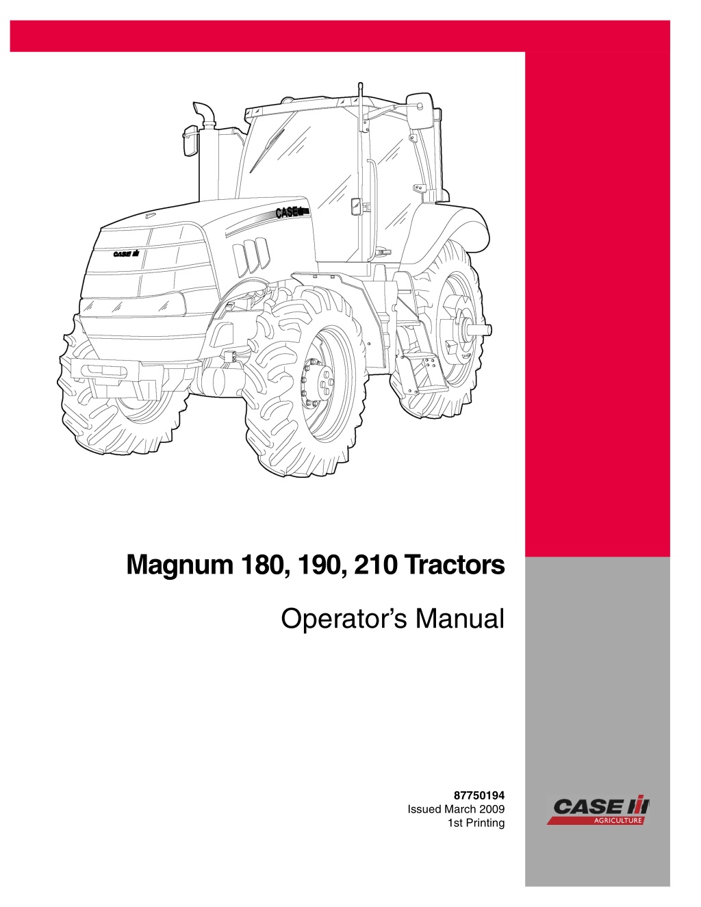
Case IH Magnum 180 Magnum 190 Magnum 210 Tractors Operator’s Manual Instant Download (Publication No.87750194)
Please open the website below to get the complete manualnn//
Download Presentation

Please find below an Image/Link to download the presentation.
The content on the website is provided AS IS for your information and personal use only. It may not be sold, licensed, or shared on other websites without obtaining consent from the author. Download presentation by click this link. If you encounter any issues during the download, it is possible that the publisher has removed the file from their server.
E N D
Presentation Transcript
Magnum 180, 190, 210 Tractors Operator s Manual 87750194 Issued March 2009 1st Printing 2009 CNH America LLC. All Rights Reserved. Case IH is a registered trademark of CNH America LLC. CNH America LLC 700 State Street Racine, WI. 53404 U.S.A. Printed in U.S.A.
OPERATOR'S MANUAL Magnum 180 Magnum 190 Magnum 210 Rac - 87750194 Issue 0 - 18/03/2009
Contents 1 GENERAL INFORMATION Personal safety............................................................................. 1-1 Proposition 65 .............................................................................. 1-2 Product identification ....................................................................... 1-3 Note to the Owner .......................................................................... 1-4 Tractor intended use........................................................................ 1-4 Manual storage............................................................................. 1-5 Product identification ....................................................................... 1-6 Component location ........................................................................ 1-8 2 SAFETY INFORMATION Safety rules................................................................................. 2-1 ROPS and CSF............................................................................. 2-6 Safety decals ............................................................................... 2-7 3 CONTROLS/INSTRUMENTS ACCESS TO OPERATOR S PLATFORM Tractor access.......................................................................... 3-1 OPERATOR S SEAT Overview ............................................................................... 3-2 Control identification.................................................................... 3-3 INSTRUCTOR S SEAT Overview ............................................................................... 3-6 FORWARD CONTROLS Steering column ........................................................................ 3-7 Front console.......................................................................... 3-10 Pedal controls ......................................................................... 3-12 LH SIDE CONTROLS Hand brake ............................................................................ 3-13 RH SIDE CONTROLS Armrest console ....................................................................... 3-14 Multi-function handle .................................................................. 3-15 Control panel .......................................................................... 3-18 Remote valve controls................................................................. 3-26 Joystick................................................................................ 3-27 Armrest compartment ................................................................. 3-29 Adjusting the armrest console......................................................... 3-30 REARWARD CONTROLS Fender console........................................................................ 3-31 Automatic temperature controls ....................................................... 3-34 Automatic temperature control system ................................................ 3-37 Ventilation ............................................................................. 3-38 OVERHEAD CONTROLS Interior lamps.......................................................................... 3-40 EXTERIOR CONTROLS
https://www.ebooklibonline.com Hello dear friend! Thank you very much for reading. Enter the link into your browser. The full manual is available for immediate download. https://www.ebooklibonline.com
Rear fender............................................................................ 3-41 INSTRUMENT CLUSTER Overview .............................................................................. 3-42 Gauges ................................................................................ 3-42 Status and warning icons.............................................................. 3-43 Dedicated display...................................................................... 3-46 Programmable display................................................................. 3-47 Keypad ................................................................................ 3-48 Standard instrumentation.............................................................. 3-50 Performance instrumentation.......................................................... 3-55 4 OPERATING INSTRUCTIONS COMMISSIONING THE UNIT Before starting the engine .............................................................. 4-1 STARTING THE UNIT Normal engine starting ................................................................. 4-4 Cold starting aids....................................................................... 4-6 Cold temperature operation ............................................................ 4-7 STOPPING THE UNIT Stopping the engine .................................................................... 4-9 MOVING THE UNIT Powershift transmission ............................................................... 4-10 Inching pedal and throttle.............................................................. 4-11 Transmission controls ................................................................. 4-12 Dedicated display...................................................................... 4-14 Driving the vehicle..................................................................... 4-15 Autoshift road and field................................................................ 4-17 Go To feature.......................................................................... 4-23 Speed matching ....................................................................... 4-23 Setting reverse gear ratios ............................................................ 4-25 Transmission errors and calibration ................................................... 4-26 Creeper gears ......................................................................... 4-27 Mechanical front drive (MFD).......................................................... 4-28 Differential lock system................................................................ 4-30 Suspended axle ....................................................................... 4-32 Engine power management ........................................................... 4-33 Ride control............................................................................ 4-35 Constant engine speed................................................................ 4-36 Electronic end of row system.......................................................... 4-39 PARKING THE UNIT Park brake and electronic park lock (EPL) ............................................ 4-50 5 TRANSPORT OPERATIONS ROAD TRANSPORT Tractor warning lamps and SMV symbol ............................................... 5-1 Wide transport marker light............................................................. 5-2 Tractor warning lamps.................................................................. 5-4 Safe transport speed ................................................................... 5-5
Implement warning lamps and SMV symbol ........................................... 5-6 Safety chain ............................................................................ 5-7 SHIPPING TRANSPORT Securing the tractor for shipping ....................................................... 5-8 RECOVERY TRANSPORT Safety rules............................................................................. 5-9 6 WORKING OPERATIONS GENERAL INFORMATION Before operating the vehicle............................................................ 6-1 Guidelines .............................................................................. 6-2 REAR PTO Safety rules......................................................................... 6-3 Connecting the PTO................................................................ 6-6 PTO operation...................................................................... 6-8 Two speed PTO systems.......................................................... 6-10 Auto PTO operation ............................................................... 6-11 PTO fender switch operation ...................................................... 6-13 THREE POINT HITCH Connecting three-point hitch implements.......................................... 6-14 Three-point hitch adjustments..................................................... 6-15 Hitch controls and settings ........................................................ 6-22 Draft control ....................................................................... 6-27 Position and ride control........................................................... 6-30 DRAWBARS AND TOWING ATTACHMENTS Safety rules........................................................................ 6-32 Adjusting the drawbar ............................................................. 6-33 HYDRAULIC TRAILER BRAKES Trailer brake connections.......................................................... 6-35 AUXILIARY POWER CONNECTIONS Auxiliary power and lighting ....................................................... 6-36 Cab power connections ........................................................... 6-38 HYDRAULIC REMOTE CONTROL VALVES Valve couplers and connections................................................... 6-40 Transport lock ..................................................................... 6-45 Operating the controls............................................................. 6-46 Remote valve display screens..................................................... 6-50 Rear fender controls............................................................... 6-53 Joystick operation ................................................................. 6-54 BALLASTING THE TRACTOR Guidelines ......................................................................... 6-56 Tire load and inflation charts ...................................................... 6-60 Weights, cast metal and liquid..................................................... 6-66 Wheel slip and power hop performance .......................................... 6-74 MECHANICAL FRONT DRIVE (MFD) AXLES
Tire combinations and tread positions............................................. 6-76 Steering and oscillation stops ..................................................... 6-81 REAR AXLE Rear wheel installation ............................................................ 6-86 Rear wheel tread settings ......................................................... 6-88 7 MAINTENANCE GENERAL INFORMATION Safety rules............................................................................. 7-1 Opening the hood ...................................................................... 7-2 Closing the hood ....................................................................... 7-3 Battery access and service............................................................. 7-4 Tire and rim service..................................................................... 7-6 Tractor jacking points................................................................... 7-8 Capacities ............................................................................. 7-10 Consumables.......................................................................... 7-12 Electrical component location ......................................................... 7-16 MAINTENANCE CHART Maintenance Chart .................................................................... 7-20 At warning message display Air filter service icon/message......................................................... 7-21 Fuel filter water separator ............................................................. 7-24 Every 10 hours or daily Engine coolant level ................................................................... 7-25 Engine oil level ........................................................................ 7-26 Windshield washer fluid level.......................................................... 7-27 First 50 hours Dealer performed service.............................................................. 7-28 Every 50 hours Coolers and condenser................................................................ 7-29 Cab air filter............................................................................ 7-31 Grease fittings ......................................................................... 7-34 Wheel bolt torque...................................................................... 7-40 Tire pressure .......................................................................... 7-41 Every 300 hours Battery water level..................................................................... 7-42 Fan belt................................................................................ 7-44 Transmission oil level.................................................................. 7-45 Mechanical front drive (MFD) gearbox ................................................ 7-46 Park brake............................................................................. 7-47 Every 600 hours Engine oil and filter .................................................................... 7-48 Hydraulic filter(s) ...................................................................... 7-50 Engine primary air filter................................................................ 7-51 Engine air intake hoses................................................................ 7-54 Fuel filters ............................................................................. 7-56
Differential and planetary oil........................................................... 7-58 Every 1200 hours or annually Cab air filter............................................................................ 7-59 Hydraulic filter(s) ...................................................................... 7-61 Transmission oil ....................................................................... 7-66 Differential and planetary oil........................................................... 7-69 Mechanical front drive (MFD) gearbox ................................................ 7-72 Battery water level..................................................................... 7-73 Every 1200 hours or two years Engine coolant......................................................................... 7-75 Engine secondary air filter............................................................. 7-78 Engine valve adjustment .............................................................. 7-81 Blowby filter............................................................................ 7-82 Every 36 months Air conditioning system................................................................ 7-82 As required Pre-filter and water trap ............................................................... 7-83 Fuel tank vent filter .................................................................... 7-85 Fan belt................................................................................ 7-86 Spark arresting muffler ................................................................ 7-90 Remote valve collection bottle......................................................... 7-92 Cab fabric and carpet.................................................................. 7-92 Tractor exterior ........................................................................ 7-93 Seat belt ............................................................................... 7-94 STORAGE Preparing for storage.............................................................. 7-95 Removing from storage............................................................ 7-95 ELECTRICAL SYSTEM Radio or audio system................................................................. 7-97 Battery removal and installation ....................................................... 7-98 Battery - Charging .................................................................... 7-100 Head light - Replace.................................................................. 7-101 Front work light - Replace ............................................................ 7-107 Fender tail light and warning light .................................................... 7-109 Roof front warning and work light .................................................... 7-111 Roof rear warning light ............................................................... 7-114 High intensity work light .............................................................. 7-116 Wide transport marker light........................................................... 7-118 Rotating beacon light................................................................. 7-119 Interior light - Replace ................................................................ 7-120 8 TROUBLESHOOTING ALARM(S) Display warnings ................................................................... 8-1 Automatic engine shut down ....................................................... 8-8 Fault reporting .................................................................. 8-9
SYMPTOM(S) Engine symptoms ................................................................. 8-11 Transmission symptoms........................................................... 8-13 Hydraulic symptoms............................................................... 8-14 Hitch symptoms ................................................................... 8-15 Brake symptoms................................................................... 8-16 Cab environment symptoms....................................................... 8-16 Electrical power system symptoms................................................ 8-17 9 SPECIFICATIONS Engine specifications....................................................................... 9-1 Power train specifications .................................................................. 9-2 Operating speeds........................................................................... 9-4 Vehicle dimensions and shipping weight ................................................... 9-7 Maximum operating weight................................................................. 9-8 10 ACCESSORIES Front wheel fenders ....................................................................... 10-1 Farming system displays .................................................................. 10-5 Chemical tank mounting................................................................... 10-6 Loader connection and operation ......................................................... 10-8 General accessories....................................................................... 10-9 11 FORMS AND DECLARATIONS First service dealer copy .................................................................. 11-1 First service customer copy ............................................................... 11-3
GENERAL INFORMATION - 1 1 - GENERAL INFORMATION Personal safety THIS SAFETY ALERT SYMBOL INDICATES IMPORTANT SAFETY MESSAGES IN THIS MANUAL. WHEN YOU SEE THIS SYMBOL, CAREFULLY READ THE MESSAGE THAT FOLLOWS AND BE ALERT TO THE POSSIBILITY OF DEATH OR SERIOUS INJURY. Throughout this manual and on the machine s safety decals, you will find precautionary statements: DANGER< WARNING or CAUTION followed by special instructions or ISO two panel safety pictorial symbols. These precau- tions are intended for your personal safety. Failure to follow the DANGER, WARNING or CAUTION instructions may result in death or serious bodily injury. DANGER, WARNING or CAUTION are defined as follows: DANGER: Indicates an immediate hazardous situation that, if not avoided, will result in death or serious injury. The color associated with Danger is RED. WARNING: Indicates a potentially hazardous situation that, if not avoided, could result in death or serious injury. The color associated with Warning is ORANGE. CAUTION: Indicates a potentially hazardous situation that, if not avoided, could result in minor or moderate injury. It may also be used to alert against unsafe practices. The color associated with Caution is YELLOW. ISO two panel pictorial symbol decals are defined as follows: The first panel indicates the nature of the hazard. The second panel indicates the appropriate avoidance of the hazard Background color is YELLOW. Prohibition symbols such as and if used are RED. WARNING IMPROPER OPERATION OF THIS MACHINE CAN CAUSE DEATH OR SERIOUS INJURY. BEFORE USING THIS MACHINE, MAKE CERTAIN THAT EVERY OPERATOR: Is instructed in safe and proper use of the machine. Reads and understands the Manual(s) pertaining to the machine. Reads and understands ALL Safety Decals on the machine. Clears the area of other persons. Learns and practices safe use of machine controls in a safe, clear area before operating this machine on a job site. It is your responsibility to observe pertinent laws and regulations and follow CNH America LLC instructions on machine operation and maintenance. 1 - 1
GENERAL INFORMATION - 1 CNH America LLC technical manuals Manuals are available from your Dealer for the operation, service and repair of your machine. For prompt convenient service, contact your Dealer for assistance in obtaining the manuals for your machine. Your Dealer can expedite your order for Operators Manuals, Parts Catalogs, Repair Manuals and maintenance records. Always give the Machine Name, Model and P.I.N. (product identification number) of your machine so your Dealer can provide the correct manuals for your machine. The company is continually striving to improve its products and therefore reserves the right to make improvements and changes when it becomes practical and possible to do so, without incurring any obligation to make changes or additions to the equipment sold previously. All data given in this manual is subject to production variations. IMPORTANT: OPERATING AND SERVICE MES- SAGES DISPLAYED ON THE ELECTRONIC OPERATING PANEL MAY VARY FROM WHAT IS SHOWN IN THE OP- ERATOR S MANUAL. SHOULD THIS OCCUR ADHERE TO THE LATEST INSTRUCTION ON THE ELECTRONIC OPERATING PANEL. Dimensions and weights are approximate only and the illustrations do not necessarily show the machine in standard condition. For exact information about any particular machine, please consult your dealer. Proposition 65 1 RCIL08CCH001EAA 1 - 2
GENERAL INFORMATION - 1 Product identification 1 RCPH09CCH012BAB The right hand and left hand side of the tractor used in this manual are the same as your right hand and left hand when sitting in the tractor seat looking forward. 1 - 3
GENERAL INFORMATION - 1 Note to the Owner This manual contains important information about the safe operation, adjustment and routine maintenance of your Magnum series tractor. The manual is divided into eleven chapters as outlined in the table of contents. Refer to the index at the end of this manual for locating specific items about your tractor. This Operator s Manual is to be stored in the manual com- partment behind the operator s seat in the vehicle. Make sure this manual is in good condition. Contact your dealer to obtain additional manuals. any further information or assistance about your machine. Your dealer has approved service parts. Your dealer has technicians with special training that know the best meth- ods of repair and maintenance for your tractor. Contact your dealer for Do NOT operate or permit anyone to operate or service this machine until you or the other persons have read this manual. Use only trained operators who have demon- strated the ability to operate and service this machine cor- rectly and safely. Tractor intended use Magnum series tractors with standard equipment and au- thorizedattachments, areintendedtobeusedforcustom- ary farming and related agriculture operations. Farming implements and attachments for loading and moving ma- terials can be used on the tractor where recommended and approved by CASEIH. Installation of utility (dozer) blades, tile plows, or push bars on the tractor is not rec- ommended. Any tractor damage resulting from the instal- lation and/or use of such equipment is not covered by the tractor warranty. Consult an authorized dealer or CNH America LLC on changes, additions or modifications that can be required for this machine to comply with various regulations and safety requirements. Unauthorized modifications will cause serious injury or death. unauthorized modifications is responsible for the conse- quences. Anyone making such 1 - 4
GENERAL INFORMATION - 1 Manual storage 1 RCPH08CCH002FAB Keep the Operator s Manual in the storage compartment provided on your tractor. The Operator s Manual must be available for use by all operators. 1 - 5
GENERAL INFORMATION - 1 Product identification Tractor model and product identification number Model : PIN NOTE: Located on right hand front frame casting. 1 RCPH08CCH625AAB Roll over protection system (ROPS) serial number NOTE: Located on the right hand cab floor. 2 RCPH09CCH294AAB Engine serial number NOTE: Located on the rear left hand side of the engine, behind the hood support. NOTE: Hood support removed for illustration clarity. 3 RCPH08CCH828AAB 1 - 6
GENERAL INFORMATION - 1 Transmission serial number NOTE: Located on the right hand side of the transmission behind and to the left of the battery carrier. 4 RCPH08CCH627AAB Axle serial number MFD axle: Located on the front right hand side of the axle housing (shown). Scissors suspended axle: Located on the front right hand side of the axle housing (not shown). 5 RCPH09CCH277AAB Driveline serial number Located on the right hand side of the drop box below the exhaust elbow. 6 RCIL09CCH002BAB 1 - 7
GENERAL INFORMATION - 1 Component location 1 RCPH09CCH001FAB 5. Hood 6. Front weight bracket 7. Exhaust stack 8. Wide transport marker (in storage position) 9. Amber warning lamps 10. Work lamps 11. Road/work lamps 12. HID lamp (if equipped) 1. ROPS cab 2. Hand rail 3. Steps 4. Fuel tank 13. Amber reflector 1 - 8
GENERAL INFORMATION - 1 2 RCPH09CCH002FAB 5. Drawbar 6. Amber warning lamps 7. Tail/brake lamp 8. SMV symbol 9. Wide transport marker 10. Red reflector 11. Orange reflector 12. Roof/fender work lamps 1. ROPS cab 2. Rear view mirror 3. Rear hitch 4. Power takeoff (PTO) 1 - 9
Suggest: If the above button click is invalid. Please download this document first, and then click the above link to download the complete manual. Thank you so much for reading
GENERAL INFORMATION - 1 1 - 10
https://www.ebooklibonline.com Hello dear friend! Thank you very much for reading. Enter the link into your browser. The full manual is available for immediate download. https://www.ebooklibonline.com

