BOBCAT 320 322 EXCAVATOR Service Repair Manual Instant Download (320 SN 223911001 & Above, 322 SN 224011001 & Above)
Please open the website below to get the complete manualnn// n

Download Presentation

Please find below an Image/Link to download the presentation.
The content on the website is provided AS IS for your information and personal use only. It may not be sold, licensed, or shared on other websites without obtaining consent from the author. Download presentation by click this link. If you encounter any issues during the download, it is possible that the publisher has removed the file from their server.
E N D
Presentation Transcript
320 322 Service Manual 320 - S/N 223911001 & Above 322 - S/N 224011001 & Above (G Series) Printed in U.S.A. 6902668 (7-06) Bobcat Company 2006
MAINTENANCE SAFETY Instructions are necessary before operating or servicing machine. Read and understand the Operation & Maintenance Manual, Operator s Handbook and signs (decals) on machine. Follow warnings and instructions in the manuals when making repairs, adjustments or servicing. Check for correct function after adjustments, repairs or service. Untrained operators and failure to follow instructions can cause injury or death. WARNING W-2003-0903 Safety Alert Symbol: This symbol with a warning statement, means: Warning, be alert! Your safety is involved! Carefully read the message that follows. CORRECT CORRECT CORRECT B-10731A B-19964 B-19959 Never service the Bobcat Compact Excavator without instructions. Cleaning and maintenance are required daily. Use the correct procedure to lift and support the excavator. WRONG WRONG WRONG B-19965 B-19966 B-19960 Always lower the bucket and blade to the ground before doing any maintenance. Never modify equipment or add attachments not approved by Bobcat Company. Have welding or grinding painted parts. Wear dust mask when grinding painted parts. Toxic dust and gas can be produced. good ventilation when Vent exhaust to outside when engine must be run for service. Exhaust system must be tightly sealed. Exhaust fumes can kill without warning. WRONG WRONG WRONG B-19958 B-19798 B-19962 Lead-acid flammable and explosive gases. Keep arcs, sparks, flames and lighted tobacco batteries. Batteries contain acid which burns eyes or skin on contact. Wear protective clothing. If acid contacts body, flush well with water. For eye contact flush well and get immediate attention. batteries produce Stop, cool and clean engine of flammable materials checking fluids. Never service or adjust machine with the engine running unless instructed to do so in the manual. Avoid contact hydraulic fluid or diesel fuel under pressure. It can penetrate the skin or eyes. Never fill fuel tank with engine running, while smoking, or when near open flame. Maintenance procedures which are given in the Operation & Maintenance Manual can be performed by the owner/ operator without any specific technical training. Maintenance procedures which are not in the Operation & Maintenance Manual must be performed ONLY BY QUALIFIED BOBCAT SERVICE PERSONNEL. Always use genuine Bobcat replacement parts. The Service Safety Training Course is available from your Bobcat dealer. Keep body, jewelry and clothing away from moving parts, electrical contact, hot parts and exhaust. Wear eye protection to guard from battery acid, compressed springs, fluids under pressure and flying debris when engines are running or tools are used. Use eye protections approved for type of welding. Keep tailgate closed except for service. Close and latch tailgate before operating the excavator. before away from with leaking medical MSW28-0805
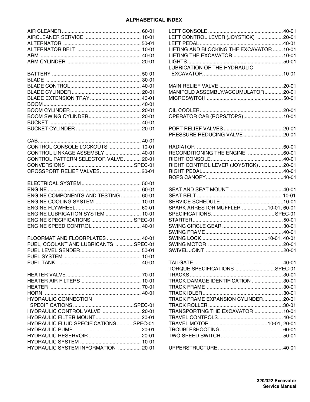
ALPHABETICAL INDEX LEFT CONSOLE .....................................................40-01 LEFT CONTROL LEVER (JOYSTICK) ..................20-01 LEFT PEDAL...........................................................40-01 LIFTING AND BLOCKING THE EXCAVATOR .......10-01 LIFTING THE EXCAVATOR ...................................10-01 LIGHTS....................................................................50-01 LUBRICATION OF THE HYDRAULIC EXCAVATOR ........................................................10-01 AIR CLEANER........................................................ 60-01 AIRCLEANER SERVICE ........................................ 10-01 ALTERNATOR .......................................................50-01 ALTERNATOR BELT ............................................. 10-01 ARM ....................................................................... 40-01 ARM CYLINDER .................................................... 20-01 BATTERY ............................................................... 50-01 BLADE ................................................................... 30-01 BLADE CONTROL.................................................. 40-01 BLADE CYLINDER................................................. 20-01 BLADE EXTENSION TRAY.................................... 40-01 BOOM..................................................................... 40-01 BOOM CYLINDER.................................................. 20-01 BOOM SWING CYLINDER..................................... 20-01 BUCKET ................................................................. 40-01 BUCKET CYLINDER .............................................. 20-01 MAIN RELIEF VALVE .............................................20-01 MANIFOLD ASSEMBLY/ACCUMULATOR.............20-01 MICROSWITCH ......................................................50-01 OIL COOLER...........................................................20-01 OPERATOR CAB (ROPS/TOPS)............................10-01 PORT RELIEF VALVES..........................................20-01 PRESSURE REDUCING VALVE............................20-01 CAB......................................................................... 40-01 CONTROL CONSOLE LOCKOUTS....................... 10-01 CONTROL LINKAGE ASSEMBLY ......................... 40-01 CONTROL PATTERN SELECTOR VALVE............ 20-01 CONVERSIONS ...............................................SPEC-01 CROSSPORT RELIEF VALVES.............................20-01 RADIATOR .............................................................60-01 RECONDITIONING THE ENGINE .........................60-01 RIGHT CONSOLE...................................................40-01 RIGHT CONTROL LEVER (JOYSTICK).................20-01 RIGHT PEDAL.........................................................40-01 ROPS CANOPY.......................................................40-01 ELECTRICAL SYSTEM.......................................... 50-01 ENGINE .................................................................. 60-01 ENGINE COMPONENTS AND TESTING .............. 60-01 ENGINE COOLING SYSTEM................................. 10-01 ENGINE FLYWHEEL.............................................. 60-01 ENGINE LUBRICATION SYSTEM ......................... 10-01 ENGINE SPECIFICATIONS ..............................SPEC-01 ENGINE SPEED CONTROL .................................. 40-01 SEAT AND SEAT MOUNT .....................................40-01 SEAT BELT ............................................................ 10-01 SERVICE SCHEDULE ............................................10-01 SPARK ARRESTOR MUFFLER ..................10-01, 60-01 SPECIFICATIONS.............................................SPEC-01 STARTER................................................................50-01 SWING CIRCLE GEAR...........................................30-01 SWING FRAME.......................................................40-01 SWING LOCK...............................................10-01, 40-01 SWING MOTOR .....................................................20-01 SWIVEL JOINT .......................................................20-01 FLOORMAT AND FLOORPLATES ........................ 40-01 FUEL, COOLANT AND LUBRICANTS .............SPEC-01 FUEL LEVEL SENDER........................................... 50-01 FUEL SYSTEM....................................................... 10-01 FUEL TANK ............................................................ 40-01 TAILGATE ...............................................................40-01 TORQUE SPECIFICATIONS ............................SPEC-01 TRACKS..................................................................30-01 TRACK DAMAGE IDENTIFICATION ......................30-01 TRACK FRAME ......................................................30-01 TRACK IDLER.........................................................30-01 TRACK FRAME EXPANSION CYLINDER..............20-01 TRACK ROLLER.....................................................30-01 TRANSPORTING THE EXCAVATOR.....................10-01 TRAVEL CONTROLS..............................................40-01 TRAVEL MOTOR .........................................10-01, 20-01 TROUBLESHOOTING ............................................60-01 TWO SPEED SWITCH............................................50-01 HEATER VALVE..................................................... 70-01 HEATER AIR FILTERS .......................................... 10-01 HEATER ................................................................. 70-01 HORN .................................................................... 40-01 HYDRAULIC CONNECTION SPECIFICATIONS...........................................SPEC-01 HYDRAULIC CONTROL VALVE ........................... 20-01 HYDRAULIC FILTER MOUNT................................ 20-01 HYDRAULIC FLUID SPECIFICATIONS...........SPEC-01 HYDRAULIC PUMP................................................ 20-01 HYDRAULIC RESERVOIR..................................... 20-01 HYDRAULIC SYSTEM ........................................... 10-01 HYDRAULIC SYSTEM INFORMATION ................ 20-01 UPPERSTRUCTURE..............................................40-01 320/322 Excavator Service Manual
CONTENTS SAFETY AND MAINTENANCE FOREWORD. . . . . . . . . . . . . . . . . . . . . . . . . . . . . . . . . . . . . . . . . . . III SAFETY INSTRUCTIONS . . . . . . . . . . . . . . . . . . . . . . . . . . . . . . . . V HYDRAULIC SYSTEM SERIAL NUMBER LOCATIONS. . . . . . . . . . . . . . . . . . . . . . . . . . . .IX DELIVERY REPORT. . . . . . . . . . . . . . . . . . . . . . . . . . . . . . . . . . . . . X UNDER- CARRIAGE BOBCAT EXCAVATOR IDENTIFICATION. . . . . . . . . . . . . . . . . . . .XI SAFETY AND MAINTENANCE. . . . . . . . . . . . . . . . . . . . . . . . . .10-01 UPPER- STRUCTURE & SWING SECTION HYDRAULIC SYSTEM . . . . . . . . . . . . . . . . . . . . . . . . . . . . . . . .20-01 UNDERCARRIAGE. . . . . . . . . . . . . . . . . . . . . . . . . . . . . . . . . . .30-01 eELECTRICAL sSYSTEM AND AANALYSISRI UPPERSTRUCTURE & SWING SECTION . . . . . . . . . . . . . . . .40-01 ELECTRICAL SYSTEM AND ANALYSIS. . . . . . . . . . . . . . . . . .50-01 ENGINE SERVICE . . . . . . . . . . . . . . . . . . . . . . . . . . . . . . . . . . .60-01 ENGINE SERVICE HEATER . . . . . . . . . . . . . . . . . . . . . . . . . . . . . . . . . . . . . . . . . . . . . .vii SPECIFICATIONS . . . . . . . . . . . . . . . . . . . . . . . . . . . . . . . . SPEC-01 HEATER SPECIFICATIONS 320/ 322 Excavator Service Manual I
https://www.ebooklibonline.com Hello dear friend! Thank you very much for reading. Enter the link into your browser. The full manual is available for immediate download. https://www.ebooklibonline.com
FOREWORD This manual is for the Bobcat Hydraulic Excavator mechanic. It provides necessary servicing and adjustment procedures for the hydraulic Excavator and its component parts and systems. Refer to the Operation & Maintenance Manual for operating instructions, starting procedure, daily checks, etc. A general inspection of the following items must be made after the hydraulic Excavator has had service or repair: 1. Check that ROPS/TOPS/ FOPS is in good condition and is NOT modified. 9. Safety treads must be in good condition. 2. Check mounting tightened approved. that ROPS/TOPS hardware and is 10. Check for correct function of indicator lamps (Optional on some models. is Bobcat 3. The seat belt must be correctly installed, functional and in good condition. 11. Check hydraulic fluid level, engine oil level and fuel supply. 4. Inspect for loose or broken parts or connections. 12. Inspect hydraulic fluid leaks. for fuel, oil or 5. Machine legible and in the correct location. signs must be 13. Lubricate the Excavator. 6. Steering levers, control levers and foot pedals must return to neutral. Check that foot pedals lock and control lever locks are in working order. 7. Inspect the air cleaner for damage or leaks. Check the condition of the filters. 14. Check the condition of the battery and cables. Recommend to the owner that all necessary corrections be made before the machine is returned to service. 8. Check the electrical charging system. 320/ 322 Excavator Service Manual III
The following publications provide information on the safe use and maintenance of the Bobcat machine and attachments: SAFETY INSTRUCTIONS Safety Alert Symbol The Delivery Report is used to assure that complete instructions have been given to the new owner and that the machine is in safe operating condition. This symbol with a warning statement means: Warning, be alert! Your safety is involved! Carefully read the message that follows. The Operation & Maintenance Manual delivered with the machine or attachment contains operating information as well as routine maintenance and service procedures. It is a part of the machine and can be stored in a container provided on the machine. Replacement Operation & Maintenance Manuals can be ordered from your Bobcat dealer. WARNING Instructions are necessary before operating or servicing machine. Read and understand the Operation & Maintenance Handbook and signs (decals) on machine. Follow warnings and instructions in the manuals when making repairs, adjustments or servicing. Check for correct function after adjustments, repairs or service. Untrained operators and failure to follow instructions can cause injury or death. Machine signs (decals) instruct on the safe operation and care of your Bobcat machine or attachment. The signs and their locations are shown in the Operation & Maintenance Manual. Replacement signs are available from your Bobcat dealer. Manual, Operator s An Operator s Handbook fastened to the operator cab. It s brief instructions are convenient to the operator. The handbook is available from your dealer in an English edition or one of many other languages. See your Bobcat dealer for more information on translated versions. W-2003-0903 WARNING The AEM Safety Manual delivered with the machine gives general safety information. Warnings on the machine and in the manuals are for your safety. Failure to obey warnings can cause injury or death. The Service Manual and Parts Manual are available from your dealer for use by mechanics to do shop- type service and repair work. W-2044-1285 The Compact Excavator Operator Training Course is available through your www.training.bobcat.com or www.bobcat.com. This course is intended to provide rules and practices of correct operation of the Bobcat Excavator. The course is available in English and Spanish versions. local dealer or at IMPORTANT This notice identifies procedures which must be followed to avoid damage to the machine. I-2019-0284 Service Safety Training Courses are available from your Bobcat dealer or at www.training.bobcat.com or www.bobcat.com. They provide information for safe and correct service procedures. The Bobcat Compact Excavator Safety Video is available from your www.training.bobcat.com or www.bobcat.com. Bobcat dealer or at SI EXC-0206 SM 320/ 322 Excavator Service Manual V
Use the procedure in the Operation & Maintenance Manual for connecting the battery and for jump starting. SAFETY INSTRUCTIONS (CONT D) Fire Prevention The machine and attachments have components that are at high temperature under normal operating conditions. The primary source of high temperatures is the engine and exhaust system. The electrical system, if damaged or incorrectly maintained, can be a source of arcs or sparks. Use the procedure in the Operation & Maintenance Manual for cleaning the spark arrestor muffler (if equipped). Figure 1 Flammable debris (leaves, straw, etc.) must be removed regularly. If flammable debris is allowed to accumulate, it will increase fire hazard. Clean often to avoid this accumulation. Flammable compartment is a potential hazard. debris in the engine The spark arrestor muffler is designed to control the emission of hot particles from the engine and exhaust system, but the muffler and the exhaust gases are still hot. Do not use the machine where exhaust, arcs, sparks or hot components can contact flammable material, explosive dust or gases. The operator cab, engine compartment, and engine cooling system must be inspected every day and cleaned if necessary to prevent fire hazard and overheating. Know where fire extinguishers and first aid kits are located and how to use them. Fire extinguishers are available from your Bobcat dealer [Figure 1]. Check all electrical wiring and connections for damage. Keep the battery terminals clean and tight. Repair or replace any damaged part. Check fuel and hydraulic tubes, hoses and fittings for damage and leakage. Never use open flame or bare skin to check for leaks. Tighten or replace any parts that show leakage. Always clean fluid spills. Do not use gasoline or diesel fuel for cleaning parts. Use commercial nonflammable solvents. Do not use ether or starting fluids on any engine which has glow plugs. These starting aids can cause explosion and injure you or bystanders. Always clean the machine, disconnect the battery, and disconnect the wiring from the controllers before welding. Cover rubber hoses, battery and all other flammable parts. Keep a fire extinguisher near the machine when welding. Have good ventilation when grinding or welding painted parts. Wear a dust mask when grinding painted parts. Toxic dust or gas can be produced. Stop the engine and let it cool before adding fuel. NO SMOKING! SI EXC-0206 SM 320/ 322 Excavator Service Manual VII
SERIAL NUMBER LOCATIONS Engine Serial Number Always use the serial number of the Excavator when requesting service information or when ordering parts. Early or later models (identification made by serial number) may use different parts, or it may be necessary to use a different procedure in doing a specific service operation. Figure 2 1 Excavator Serial Number Figure 1 P-49279 Figure 3 1 1 P-49272 The Excavator serial number plate (Item 1) is located on the frame of the machine in the location shown [Figure 1]. Explanation of Excavator Serial Number: XXXX XXXXX P-49280 Module 2. - Production Sequence (Series) The engine serial number (Item 1) [Figure 2] & [Figure 3] is located on the engine in the locations shown. Module 1. - Model / Engine Combination 1. The four digit Model/Engine Combination Module number identifies the model number and engine combination. 2. The five digit Production Sequence Number identifies the order which the Excavator is produced. 320/ 322 Excavator Service Manual IX
DELIVERY REPORT Figure 4 B-16315 The delivery report must be filled out by the dealer and signed by the owner or operator when the Bobcat Excavator is delivered. An explanation of the form must be given to the owner. Make sure it is filled out completely [Figure 4]. 320/322 Excavator Service Manual X
BOBCAT EXCAVATOR IDENTIFICATION HYDRAULIC CONTROL LEVERS (JOYSTICKS) *CANOPY/CAB (ROPS/TOPS) GRAB HANDLES TAILGATE UPPERSTRUCTURE TRACK TRACK FRAME TIE DOWN OPERATOR S HANDBOOK GRAB HANDLES LIFT POINT ARM CYLINDER AUXILIARY HYDRAULIC QUICK COUPLERS (OPTIONAL) OPERATOR SEAT WITH SEAT BELT BUCKET CYLINDER BOOM BOOM CYLINDER ARM BUCKET LINK BLADE CYLINDER TIE DOWNS/ LIFT POINT BLADE BUCKET B-23067 * FOGS (Falling Object Guards) is available from your Bobcat Excavator dealer. B-23066 320/ 322 Excavator Service Manual XI
SAFETY & MAINTENANCE SAFETY AND MAINTENANCE AIR CLEANER SERVICE . . . . . . . . . . . . . . . . . . . . . . . . . . . . 10-60-1 Daily Check . . . . . . . . . . . . . . . . . . . . . . . . . . . . . . . . . . . . 10-60-1 Replacing The Filters. . . . . . . . . . . . . . . . . . . . . . . . . . . . . 10-60-1 SAFETY & MAINTENANCE ALTERNATOR BELT . . . . . . . . . . . . . . . . . . . . . . . . . . . . . . 10-140-1 Adjusting The Alternator Belt. . . . . . . . . . . . . . . . . . . . . . 10-140-1 CONTROL CONSOLE LOCKOUTS . . . . . . . . . . . . . . . . . . . 10-160-1 Inspection And Maintenance . . . . . . . . . . . . . . . . . . . . . . 10-160-1 ENGINE COOLING SYSTEM. . . . . . . . . . . . . . . . . . . . . . . . . 10-70-1 Checking Coolant Level. . . . . . . . . . . . . . . . . . . . . . . . . . . 10-70-1 Cleaning The Cooling System . . . . . . . . . . . . . . . . . . . . . . 10-70-1 Replacing The Coolant . . . . . . . . . . . . . . . . . . . . . . . . . . . 10-70-2 DRIVE SYSTEM ENGINE LUBRICATION SYSTEM . . . . . . . . . . . . . . . . . . . . . 10-90-1 Checking Engine Oil . . . . . . . . . . . . . . . . . . . . . . . . . . . . . 10-90-1 Oil Chart. . . . . . . . . . . . . . . . . . . . . . . . . . . . . . . . . . . . . . . 10-90-1 Replacing Oil And Filter. . . . . . . . . . . . . . . . . . . . . . . . . . . 10-90-2 ELECTRICAL SYSTEM & ANALYSIS FUEL SYSTEM . . . . . . . . . . . . . . . . . . . . . . . . . . . . . . . . . . . . 10-80-1 Draining The Fuel Tank . . . . . . . . . . . . . . . . . . . . . . . . . . . 10-80-3 Filling The Fuel Tank . . . . . . . . . . . . . . . . . . . . . . . . . . . . . 10-80-1 Fuel Specifications. . . . . . . . . . . . . . . . . . . . . . . . . . . . . . . 10-80-1 Removing Air From The Fuel System . . . . . . . . . . . . . . . . 10-80-3 Removing Water From The Fuel Filter. . . . . . . . . . . . . . . . 10-80-2 Replacing The Fuel Filter. . . . . . . . . . . . . . . . . . . . . . . . . . 10-80-2 ENGINE SERVICE SPECIFICATIONS HEATER AIR FILTERS. . . . . . . . . . . . . . . . . . . . . . . . . . . . . . 10-61-1 Fresh Air Filter . . . . . . . . . . . . . . . . . . . . . . . . . . . . . . . . . . 10-61-1 Recirculation Filter. . . . . . . . . . . . . . . . . . . . . . . . . . . . . . . 10-61-1 HYDRAULIC SYSTEM . . . . . . . . . . . . . . . . . . . . . . . . . . . . . 10-100-1 Checking And Adding Hydraulic Oil. . . . . . . . . . . . . . . . . 10-100-1 Diagnostic Couplers. . . . . . . . . . . . . . . . . . . . . . . . . . . . . 10-100-1 Replacing Hydraulic Oil . . . . . . . . . . . . . . . . . . . . . . . . . . 10-100-2 Replacing The Hydraulic Filter. . . . . . . . . . . . . . . . . . . . . 10-100-2 LIFTING AND BLOCKING THE EXCAVATOR. . . . . . . . . . . . 10-10-1 Procedure . . . . . . . . . . . . . . . . . . . . . . . . . . . . . . . . . . . . . 10-10-1 LIFTING THE EXCAVATOR. . . . . . . . . . . . . . . . . . . . . . . . . . 10-12-1 LUBRICATION OF THE HYDRAULIC EXCAVATOR. . . . . . 10-110-1 Continued On Next Page 320/322 Excavator Service Manual 10-01
SAFETY AND MAINTENANCE (CONTD) OPERATOR CAB ROPS/TOPS . . . . . . . . . . . . . . . . . . . . . . . 10-20-1 Cab Door . . . . . . . . . . . . . . . . . . . . . . . . . . . . . . . . . . . . . . 10-20-1 Emergency Exits . . . . . . . . . . . . . . . . . . . . . . . . . . . . . . . . 10-20-1 Front Window. . . . . . . . . . . . . . . . . . . . . . . . . . . . . . . . . . . 10-20-2 Right Side Windows. . . . . . . . . . . . . . . . . . . . . . . . . . . . . . 10-20-4 SEAT BELT. . . . . . . . . . . . . . . . . . . . . . . . . . . . . . . . . . . . . . 10-150-1 Inspection And Maintenance . . . . . . . . . . . . . . . . . . . . . . 10-150-1 SERVICE SCHEDULE . . . . . . . . . . . . . . . . . . . . . . . . . . . . . . 10-50-1 Chart . . . . . . . . . . . . . . . . . . . . . . . . . . . . . . . . . . . . . . . . . 10-50-1 SPARK ARRESTOR MUFFLER . . . . . . . . . . . . . . . . . . . . . . 10-130-1 SWING LOCK . . . . . . . . . . . . . . . . . . . . . . . . . . . . . . . . . . . . . 10-11-1 TAILGATE. . . . . . . . . . . . . . . . . . . . . . . . . . . . . . . . . . . . . . . . 10-40-1 Adjusting The Bumper . . . . . . . . . . . . . . . . . . . . . . . . . . . . 10-40-1 Adjusting The Tailgate Latch . . . . . . . . . . . . . . . . . . . . . . . 10-40-1 Opening And Closing The Tailgate . . . . . . . . . . . . . . . . . . 10-40-1 TRANSPORTING THE EXCAVATOR . . . . . . . . . . . . . . . . . . 10-30-1 TRAVEL MOTOR . . . . . . . . . . . . . . . . . . . . . . . . . . . . . . . . . 10-120-1 Checking Oil Level. . . . . . . . . . . . . . . . . . . . . . . . . . . . . . 10-120-1 Draining The Travel Motor . . . . . . . . . . . . . . . . . . . . . . . . 10-120-1 320/322 Excavator Service Manual 10-02
LIFTING AND BLOCKING THE EXCAVATOR Procedure Always park the machine on a level surface. Figure 10-10-1 P-49769 Raise one side of the machine (approximately 4 inches) using the boom and arm as shown in [Figure 10-10-1]. Raise the blade fully and install jackstands under the blade and the track frame. Lower the machine until all machine weight is on the jackstands. Stop the engine. WARNING Put jackstands under the blade and rear corners of the undercarriage before working under the machine. Failure to block up the machine may allow it to move or fall and result in injury or death W-2218-1195 WARNING AVOID INJURY OR DEATH Keep fingers and hands out of pinch points when checking the track tension. W-2142-0189 320/322 Excavator Service Manual 10-10-1
SWING LOCK Figure 10-11-3 Figure 10-11-2 1 1 P-30224 P-30224 P-30223 Move the lever (Item 1) [Figure 10-11-3] up to disengage the upperstructure from the track frame. Secure the lever in the unlocked position. Move the lever (Item 1) [Figure 10-11-2]down to engage the Slew Lock. When the Slew Lock is engaged (locked), the upperstructure of the Excavator is locked to the track frame and will not rotate. The upper structure must be parallel to the track frame to engage the Slew Lock. WARNING AVOID INJURY The slew lock lever must be engaged when transporting the machine. W-2197-1203 320/ 322 Excavator Service Manual 10-11-1
LIFTING THE EXCAVATOR Figure 10-12-5 Figure 10-12-4 2 1 1 1 P-49779 P-49777 Fasten chains to the ends of the blade (Item 1) [Figure 10-12-4] and [Figure 10-12-5] and up to a lifting fixture above the canopy/cab. The lifting fixture must extend over the sides of the canopy/cab to prevent the chains from hitting the ROPS/TOPS. Fully extend the cylinders of the bucket, arm, and boom so that the Excavator is in the position as shown [Figure 10-12-4]. Engage the upperstructure slew lock. (See SWING LOCK on Page 10-11-1.) Figure 10-12-6 Raise the blade all the way. Put all the control levers in neutral. 1 WARNING AVOID INJURY OR DEATH Use a lifting fixture with sufficient capacity for the weight of the Excavator plus any added attachments. Maintain center of gravity and balance when lifting. Do not swing boom or upperstructure. Engage the slew locking lever. Never lift with operator on machine. P-49778 Install a one inch (25 mm) bolt and nut (Grade 5 or 8) through the holes at the boom (Item 1) [Figure 10-12-4] and [Figure 10-12-6]. Fasten a chain from the bolt to the lift fixture. W-2202-0595 320/322 Excavator Service Manual 10-12-1
OPERATOR CAB ROPS/TOPS Cab Door Emergency Exits Figure 10-20-9 The left door, front window, and right side rear window provide exits. 3 Figure 10-20-7 2 1 P-49727 The cab door can be locked (Item 1) [Figure 10-20-9] with the same key as the starter switch. P-49726 Push the door all the way open (Item 2) [Figure 10-20-9] until the latch engages to hold the door in the open position. Figure 10-20-8 Pull the door away from the cab (Item 3) [Figure 10-20-9] to disengage the latch and close the door. P-49127 Slide the window to the front of the Excavator and exit through the side window [Figure 10-20-7], or open the front window and exit [Figure 10-20-8]. 320/322 Excavator Service Manual 10-20-1
OPERATOR CAB (ROPS / TOPS) (CONTD) Figure 10-20-12 Front Window Opening The Front Window Figure 10-20-10 1 P-49127 Use both window grab handles to pull the top of the window in [Figure 10-20-12]. Continue moving the window in and up over the operator s head until the window is fully raised. P-49097 Retract the two top window latch pins (Item 1) [Figure 10-20-10]. Figure 10-20-13 Figure 10-20-11 1 2 P-49099 1 When the window is fully raised, the latch (Item 1) will close on the bracket. Turn the two top latches (Item 2) [Figure 10-20-13] to the locked position. P-49098 Turn the two top latches (Item 1) [Figure 10-20-11] to the unlocked position. 320/322 Excavator Service Manual 10-20-2
OPERATOR CAB (ROPS/TOPS) (CONTD) Closing The Front Window Support the window while releasing both window latch pins and placing the pins in the unlocked position [Figure 10-20-13 on Page 10-20-2]. Support the window using the left grab handle and pull down on the latch (Item 1) [Figure 10-20-13 on Page 10- 20-2] to release the window. Use both window grab handles to pull the window down [Figure 10-20-12 on Page 10-20-2]. Rotate the top latches (Item 1) [Figure 10-20-11 on Page 10-20-2] to the locked position (Item 1) [Figure 10- 20-10 on Page 10-20-2]. 320/322 Excavator Service Manual 10-20-3
OPERATOR CAB (ROPS/TOPS) (CONTD) Opening the right front window Right Side Windows Figure 10-20-16 Opening the right rear window Figure 10-20-14 1 1 P-49119 Pull back on the latch (Item 1) [Figure 10-20-16]. P-49176 Figure 10-20-17 Pull forward on the latch (Item 1) [Figure 10-20-14]. Figure 10-20-15 1 1 P-49120 Pull the latch/handle (Item 1) [Figure 10-20-17] back to open the window. P-49177 Push the handle forward to close the window. Pull the latch/handle (Item 1) [Figure 10-20-15] forward to open the window. Push the handle back to close the window. 320/322 Excavator Service Manual 10-20-4
Stop the engine and remove the key. Put blocks under the front and rear of the tracks. TRANSPORTING THE EXCAVATOR When transporting the machine, observe the rules, motor vehicle laws and vehicle limit ordinances. Use a transport and towing vehicle of adequate length and capacity. Figure 10-30-19 Secure the parking brakes and block the wheels of the transport vehicle. Remove the blade extensions (If equipped). See Blade Extension Removal And Installation. (See Extension Removal And Installation on Page 30-10-1) Retract the track frame if required. See the correct Operation And Maintenance Manual for the proper procedure. Align the ramps with the center of the transport vehicle. Secure the ramps to the truck bed and be sure ramp angle does not exceed 15 degrees. P-49775 Figure 10-30-20 Use metal loading ramps with a slip resistant surface that are the correct length and width, and can support the weight of the machine. The rear of the trailer must be blocked or supported when loading or unloading the Excavator to prevent the front of the transport vehicle from raising. Determine the direction of the track movement before moving the machine (blade forward). Engage the slew lock . (See SWING LOCK on Page 10-11-1.) Figure 10-30-18 P-49776 Fasten chains to the front corners of the blade and to the tie down loop at the rear [Figure 10-30-19] & [Figure 10- 30-20] to prevent it from moving when going up or down slopes, or during sudden stops. Use chain binders to tighten the chains and then safely tie the chain binder levers to prevent loosening. WARNING P-49773 Move the machine forward onto the transport vehicle [Figure 10-30-18]. Adequately designed ramps of sufficient strength are needed to support the weight of the machine when loading onto a transport vehicle. Wood ramps can break and cause personal injury. Do not change direction of the machine while it is on the ramps. Lower the boom, arm, and bucket to the transport vehicle. W-2058-0494 320/322 Excavator Service Manual 10-30-1
TAILGATE Adjusting The Bumper Opening And Closing The Tailgate Figure 10-40-2 WARNING 1 AVOID INJURY OR DEATH Never service or adjust the machine when the engine is running unless instructed to do so in the manual. W-2012-0497 WARNING P-30227 Keep the rear door closed when operating the machine. Failure to do so could seriously injure a bystander. The door bumper (Item 1) [Figure 10-40-2] can be adjusted for alignment with the tailgate. W-2020-1285 Close the tailgate before operating the Excavator. Figure 10-40-1 Adjusting The Tailgate Latch Figure 10-40-3 1 P-49725 1 Release the latch (Item 1) [Figure 10-40-1] and pull the tailgate open. P-49742 Push firmly to close the tailgate. The door catch (Item 1) [Figure 10-40-3] can be adjusted by loosening the two bolts, moving the catch, and tightening the two bolts. Note: The tailgate can be locked using the start key. Close the tailgate before operating the Excavator. 320/322 Excavator Service Manual 10-40-1
SERVICE SCHEDULE Chart WARNING Maintenance work must be done at regular intervals. Failure to do so will result in excessive wear and early failures. The service schedule is a guide for correct maintenance of the Bobcat Excavator. Instructions are necessary before operating or servicing machine. Read and understand the Operation & Maintenance Handbook and signs (decals) on machine. Follow warnings and instructions in the manuals when making repairs, adjustments or servicing. Check for correct function after adjustments, repairs or service. Untrained operators and failure to follow instructions can cause injury or death. Manual, Operator s W-2003-0903 SERVICE SCHEDULE HOURS ITEM SERVICE REQUIRED 8-10 50 100 250 500 1000 Engine Coolant Engine Oil Hydraulic Fluid, Hoses and Tubelines Engine Air Filter and Air System Check coolant level. Add premixed coolant as needed. Check the engine oil level and add as needed. Check the hydraulic fluid level and add as needed. Check for damage and leaks. Repair or replace as needed. Check condition indicator and empty dust cup as needed. Check air system for leaks. Check and adjust track tension as needed. Check for correct operation of all indicators and lights. Check for proper function. Repair or replace as needed. Check condition. Check mounting hardware. Check condition. Check mounting hardware. Check for damaged signs (decals) and safety treads. Replace any signs or safety treads that are damaged or worn. Grease all machinery pivot points. Clean the filter as needed. Grease three fittings. Drain water and sediment from fuel tank and fuel filter. Check battery, cables, connections and electrolyte level. Add distilled water as needed. Replace oil & filter. Use CD or better grade oil and Bobcat filter. Check condition of belt and adjust as needed. Clean the spark chamber. Replace fuel filter. Check lubricant level in both travel motors. Clean debris from the radiator fins. Replace the filter. Replace the air cleaner filter. Check the alternator and starter connections. Check and adjust the engine valve clearance. Replace the filter. Replace lubricant in both travel motors. Drain and flush the cooling system. Replace premixed coolant. Replace the hydraulic fluid and filters. Clean the reservoir. Tracks Indicators and Lights Control Console Lockout Operator Canopy/Cab Seat Belt Safety Signs and Safety Treads Pivot Points Cab Heater Air Filter (Option) Swing Circle and Pinion Fuel Tank & Filter Battery Engine Oil and Filter Alternator / Fan Belt Spark Arrestor Muffler Fuel Filter Travel Motor Radiator, & Oil Cooler Hydraulic Filter Engine Air Cleaner Alternator & Starter Engine Valves Case Drain Filter Travel Motor Engine Cooling System Hydraulic System Also at first 50 hours Also at first 100 Hours Or every 6 months. 320/322 Excavator Service Manual 10-50-1
AIR CLEANER SERVICE Replacing The Filters See the SERVICE SCHEDULE for the correct service interval. (See SERVICE SCHEDULE on Page 10-50-1.) Outer Filter Pull the locking tab (Item 2) [Figure 10-60-4]. Daily Check Turn the dust cup (Item 3) [Figure 10-60-4] counter- clockwise about 1/8 turn. Figure 10-60-4 Remove and clean the dust cup. Figure 10-60-5 1 3 2 P-30228 1 Check the condition indicator (Item 1) [Figure 10-60-4]. If the red ring shows in the condition indicator, the filter needs to be replaced. P-30229 Replace the inner filter every third time the outer filter is replaced or as indicated. Pull the outer filter (Item 1) [Figure 10-60-5] from the air cleaner housing. Check the housing for damage. Clean the housing and the seal surface. DO NOT use compressed air. Install a new outer filter. 320/322 Excavator Service Manual 10-60-1
Figure PM-7 AIR CLEANER (CONT D) Replacing The Filters (Cont d) Figure 10-60-6 2 1 1 P-30230 Install the new inner filter. [Figure PM-7]. P-30228 Install the outer filter and the dust cup. Install the dust cup and turn about 1/8 turn [Figure 10- 60-6]. Press the button on the condition indicator to remove the red ring. Push locking tab in (Item 1) [Figure 10-60-6]. Check the air intake hose and the air cleaner housing for damage. Make sure all connections are tight. Inner Filter Only replace the inner filter under the following conditions: Replace the inner filter every third time the outer filter is replaced. After the outer filter has been replaced, press the button (Item 2) [Figure 10-60-6] on the top of the condition indicator and start the engine. Run at full RPM, then reduce engine speed and stop the engine. If the red ring shows in the condition indicator, replace the inner filter. Remove the dust cup, outer filter and inner filter. NOTE: Make sure all sealing surfaces are free of dirt and debris. 320/322 Excavator Service Manual 10-60-2
HEATER AIR FILTERS Fresh Air Filter Recirculation Filter The fresh air filter must be cleaned regularly. The recirculation filter must be cleaned regularly. The filter is located at the left of the operator seat. The fresh air filter is located on the bottom of the heater, (Item 2) [Figure 10-61-8]. Figure 10-61-8 Remove the filter. Wash the filter with a mild detergent and water. Dry the filter before installing. Install the filter and secure. 1 2 P19669 The recirculation filter is located on the front of the heater panel (Item 1) [Figure 10-61-8]. Remove the knobs and remove the filter. Wash the filter with a mild detergent and water. Dry the filter before installing. Install the filter and tighten knobs. 320/322 Excavator Service Manual 10-61-1
ENGINE COOLING SYSTEM Figure 10-70-9 Check the cooling system every day to prevent over- heating, loss of performance or engine damage. 1 Cleaning The Cooling System Open the tailgate. Use air pressure or water pressure to clean the radiator and oil cooler. Checking Coolant Level WARNING P-49748 When the engine is cool, remove the radiator cap (Item 1) [Figure 10-70-9]. AVOID BURNS Do not remove radiator cap when the engine is hot. You can be seriously burned. The coolant level must be 0.750 to 1.0 inch (20 - 25 mm) below the filler neck. W-2070-1003 If the coolant level is low, add premixed coolant to the radiator. WARNING IMPORTANT Wear safety glasses to prevent eye injury when any of the following conditions exist: When fluids are under pressure. Flying debris or loose material is present. Engine is running. Tools are being used. AVOID ENGINE DAMAGE Always use the correct ratio of water to antifreeze. W-2019-1285 Too much antifreeze reduces cooling system efficiency and may cause serious premature engine damage. Too little antifreeze reduces the additives which protect the internal engine components; reduces the boiling point and freeze protection of the system. Always add a premixed solution. Adding full strength concentrated coolant can cause serious premature engine damage. I-2124-0497 320/322 Excavator Service Manual 10-70-1
ENGINE COOLING SYSTEM (CONTD) Figure PM-11 1 Replacing The Coolant See the SERVICE SCHEDULE for correct service intervals. (See SERVICE SCHEDULE on Page 10-50-1.) P-30238 Turn the upperstructure so there is access to the engine and radiator from between the tracks. Stop the engine. WARNING AVOID BURNS P-30231 Do not remove radiator cap when the engine is hot. You can be seriously burned. W-2070-1003 Open the drain valve (Item 1) [Figure PM-11] at the bottom of the radiator and drain the coolant into a container. Figure 10-70-10 Figure 10-70-12 1 1 P-49748 P-30232 When the engine is cool, loosen and remove the radiator cap (Item 1) [Figure 10-70-10]. Open the drain valve (Item 1) [Figure 10-70-12] on the engine block and drain the coolant into a container. After all the coolant is removed, close the drain valve. Recycle or dispose of the used coolant in an environmentally safe manner. Mix the coolant in a separate container. (See FUEL, COOLANT AND LUBRICANTS on Page SPEC-60-1.) NOTE: The cooling system is factory filled with propylene glycol (purple color). DO NOT mix propylene glycol with ethylene glycol. 320/322 Excavator Service Manual 10-70-2
ENGINE COOLING SYSTEM (CONTD) Replacing The Coolant (Cont d) Add premixed coolant; 47% water and 53% propylene glycol to the recovery tank if the coolant level is low. One gallon and one pint of propylene glycol mixed with one gallon of water is the correct mixture of coolant to provide a -34 F (-37 C) freeze protection. IMPORTANT AVOID ENGINE DAMAGE Always use the correct ratio of water to antifreeze. Too much antifreeze reduces cooling system efficiency and may cause serious premature engine damage. Too little antifreeze reduces the additives which protect the internal engine components; reduces the boiling point and freeze protection of the system. Always add a premixed solution. Adding full strength concentrated coolant can cause serious premature engine damage. I-2124-0497 Use a refractometer to check the condition of propylene glycol in your cooling system. Add premixed coolant until the level is correct. Run the engine until it is at operating temperature. Stop the engine. Check the coolant level and add as needed. Install the radiator cap and tighten. Add coolant to the recovery tank as needed. Close the tailgate. 320/322 Excavator Service Manual 10-70-3
FUEL SYSTEM Filling The Fuel Tank Fuel Specifications Open the tailgate. Use only clean, high quality diesel fuel, Grade No. 2 or Grade No. 1. Figure 10-80-1 The following is a suggested blending guideline which should prevent fuel gelling problems during freezing temperature 1 Temp. F (C ) +15 (9 ) Down to -20 (-29 ) Below -20 (-29 ) No. 2 No. 1 100% 50% 0% 0% 50% 100% See your fuel supplier for local recommendations. P-30228 WARNING Remove the fuel fill cap (Item 1) [Figure 10-80-1]. Stop and cool the engine before adding fuel. NO SMOKING! Failure to obey warnings can cause an explosion or fire. Use a clean, approved safety container to add fuel. Add fuel only in an area that has a free movement of air and no flames or sparks. NO SMOKING! W-2063-0887 Install and tighten the fuel fill cap. Close the tailgate. See the SERVICE SCHEDULE for the service interval when to remove water from or replace the fuel filter. (See SERVICE SCHEDULE on Page 10-50-1.) WARNING Always clean up spilled fuel or oil. Keep heat, flames, sparks or lighted tobacco away from fuel and oil. Failure to use care around combustibles can cause explosion or fire which can result in injury or death. W-2103-1285 320/322 Excavator Service Manual 10-80-1
FUEL SYSTEM (CONTD) Removing Water From The Fuel Filter Open the tailgate. Figure 10-80-2 2 1 P-30227 Loosen the drain (Item 1) [Figure 10-80-2] at the bottom of the filter to drain water from the filter. Replacing The Fuel Filter Remove the filter (Item 2) [Figure 10-80-2]. Clean the area around the filter housing. Put clean oil on the seal of the new filter. Install the fuel filter and hand tighten. Remove the air from the fuel system. See Removing Water From The Fuel Filter on Page 10-80-2 320/322 Excavator Service Manual 10-80-2
FUEL SYSTEM (CONTD) Removing Air From The Fuel System Draining The Fuel Tank After replacing the fuel filter or when the fuel tank has run out of fuel, air must be removed from the fuel system before starting the engine. See the SERVICE SCHEDULE for the correct service interval. (See SERVICE SCHEDULE on Page 10-50-1.) Figure 10-80-4 Turn the upperstructure until the fuel tank drain is centered between the rear tracks. Figure 10-80-3 3 1 2 1 P-49746 Open the fuel filter vent (Item 1) [Figure 10-80-4]. P16463 Operate the hand pump (priming bulb) (Item 2) [Figure 10-80-4] until the fuel flows from the vent with no air bubbles. Remove the access panel (Item 1) [Figure 10-80-3] on the bottom of the engine compartment. Loosen the clamp and disconnect the fuel hose. Close the vent (Item 1) [Figure 10-80-4] on the fuel filter housing. Drain the fuel into a container. Start the engine. It may be necessary to open the vent (Item 3) [Figure 10-80-4] (at the fuel injection pump) briefly until the engine runs smoothly. Reuse, recycle or dispose of fuel in an environmentally safe manner. WARNING Diesel fuel or hydraulic fluid under pressure can penetrate skin or eyes, causing serious injury or death. Fluid leaks under pressure may not be visible. Use a piece of cardboard or wood to find leaks. Do not use your bare hand. Wear safety goggles. If fluid enters skin or eyes, get immediate medical attention from a physician familiar with this injury. W-2072-0496 320/322 Excavator Service Manual 10-80-3
ENGINE LUBRICATION SYSTEM Oil Chart Checking Engine Oil Figure 10-90-6 Check the engine oil every day before starting the engine for the work shift. Figure 10-90-5 1 3 P-30231 2 Use a good quality motor oil that meets the correct API Service Classification. See the oil chart [Figure 10-90-6]. P-30235 P-30231 Open the rear door and remove the dipstick (Item 1) [Figure 10-90-5]. Keep the oil level between the marks on the dipstick. 320/322 Excavator Service Manual 10-90-1
ENGINE LUBRICATIONS SYSTEM (CONTD) Figure 10-90-7 Replacing Oil And Filter 1 See the SERVICE SCHEDULE for the service interval for replacing the engine oil and filter. (See SERVICE SCHEDULE on Page 10-50-1.) Run the engine until it is at operating temperature. Stop the engine. Open the rear door. Remove the drain plug (Item 2) [Figure 10-90-5 on Page 1]. Drain the oil into a container and recycle or dispose of used oil in an environmentally safe manner. P-30237 Remove the oil filter element (Item 3) [Figure 10-90-5 on Page 1] and clean the filter housing surface. Remove the fill cap (Item 1) [Figure 10-90-7]. Put in 3.4 qts. (3,2 L) of oil into the engine. (See FUEL, COOLANT AND LUBRICANTS on Page SPEC-60-1.) Use a genuine Bobcat filter element. Put clean oil on the filter gasket. Install the fill cap. Install the filter and hand tighten. Start the engine and let it run for several minutes. Install and tighten the oil drain plug. Stop the engine. Check for leaks at the oil filter. Check the oil level. Add oil as needed if it is not at the top mark on the dipstick. 320/322 Excavator Service Manual 10-90-2
HYDRAULIC SYSTEM Install the cap. Close the tailgate. Checking And Adding Hydraulic Oil WARNING Put the machine on a level surface. Retract the arm and bucket cylinders, put the bucket on the ground and raise the blade. Stop the engine. Always clean up spilled fuel or oil. Keep heat, flames, sparks or lighted tobacco away from fuel and oil. Failure to use care around combustibles can cause explosion or fire which can result in injury or death. Figure 10-100-8 W-2103-1285 Diagnostic Couplers Figure 10-100-10 1 1 1 P-49750 Open the tailgate. The fluid must be at the center of the sight gauge (Item 1) [Figure 10-100-8]. Remove oil fill cap (Item 2) [Figure 10-100-8]. P-30240 Figure 10-100-9 The diagnostic couplers (Item 1) [Figure 10-100-10] are located on the hydraulic block. The couplers can be used by your Bobcat dealer to check circuit pressures. 1 P-49751 Check the condition of the screen (Item 1) [Figure 10- 100-9] in the fill neck of the reservoir. The screen must be installed in fill neck when adding oil. Add the correct fluid to the reservoir until it is at the center of the sight gauge (Item 1) [Figure 10-100-8]. (See FUEL, COOLANT AND LUBRICANTS on Page SPEC-60-1.) 320/322 Excavator Service Manual 10-100-1
HYDRAULIC SYSTEM (CONTD) Replacing Hydraulic Oil Replacing The Hydraulic Filter See the SERVICE SCHEDULE for the correct service interval. (See SERVICE SCHEDULE on Page 10-50-1.) See the SERVICE SCHEDULE for the correct service interval. (See SERVICE SCHEDULE on Page 10-50-1.) Retract the arm and bucket cylinders, lower the bucket to the ground. Stop the engine. Open the tailgate. Remove and replace the hydraulic filter. Figure 10-100-11 Figure 10-100-12 1 1 2 P-49750 P-33134 Remove the filter (Item 1) [Figure 10-100-11]. A hole (Item 1) [Figure 10-100-12] is provided in the housing for ease of draining the hydraulic fluid. Clean the housing where the filter gasket makes contact. Put clean hydraulic fluid on the gasket. Install the new filter and hand tighten only. Figure 10-100-13 Start the engine. Run the Excavator through the hydraulic functions. Stop the engine. Check the fluid level at the sight gauge (Item 2) [Figure 10-100-11] and add as needed. Check the filter area for leaks. 1 P-33133 Install a funnel (Item 1) [Figure 10-100-13] in the hole. Place a container under the funnel. 320/322 Excavator Service Manual 10-100-2
HYDRAULIC SYSTEM (CONTD) Figure 10-100-15 Replacing Hydraulic Oil (Cont d) Figure 10-100-14 1 1 P-49750 Add fluid to the reservoir until it is at the center of the sight gauge (Item 1) [Figure 10-100-15]. (See FUEL, COOLANT AND LUBRICANTS on Page SPEC-60-1.) P-49752 Remove the drain plug (Item 1) [Figure 10-100-14] and drain the hydraulic fluid into the container. Run the Excavator through the hydraulic functions. Stop the engine. Check the fluid level and add as needed. IMPORTANT Fluid such as engine oil, hydraulic fluid, coolants, grease, etc. must be environmentally safe manner. Some regulations require that certain spills and leaks on the ground must be cleaned in a specific manner. See local, state and federal regulations for the correct disposal. deposed of in an I-2067-0499 IMPORTANT If the fluid is being drained because of a system failure, remove and clean all hydraulic lines. I-2045-0788 Install the drain plug. 320/322 Excavator Service Manual 10-100-3
LUBRICATION OF THE HYDRAULIC EXCAVATOR 4. Boom Swing Cylinder-Rod End, every 8-10 hours (1) [Figure 10-110-17] Lubricate the Hydraulic Excavator as specified in the SERVICE SCHEDULE for the best performance of the machine. (See SERVICE SCHEDULE on Page 10-50-1.) 5. Boom Cylinder-Base End, every 8-10 hours (1) [Figure 10-110-17] Record the operating hours each time you lubricate the Hydraulic Excavator. Figure 10-110-18 6 Always use a good quality lithium based multi-purpose grease when lubricating the Excavator. Apply the lubricant until extra grease shows. Figure 10-110-16 7 7 1 P16896 2 2 6. Boom Base Pivot, every 8-10 hours (1) [Figure 10- 110-18] 3 7. Boom Swing Pivot, every 8-10 hours (2) [Figure 10- 110-18] P15009 Ref Description (# of Fittings) 1. Blade Cylinder-Rod End, every 8-10 hours (1) [Figure 10-110-16] 2. Blade Pivots, every 8-10 hours (2) [Figure 10-110- 16] 3. Blade Cylinder-Base End, every 8-10 hours (1) [Figure 10-110-16] Figure 10-110-17 4 5 P15010 320/ 322 Excavator Service Manual 10-110-1
LUBRICATION OF THE HYDRAULIC EXCAVATOR (CONT D) 15. Bucket Pivots, every 8-10 hours (3) [Figure 10-110- 20] Figure 10-110-19 Figure 10-110-21 9 10 18 11 17 16 8 12 P15013 P-49720 8. Boom Cylinder-Rod End, every 8-10 hours (1) [Figure 10-110-19] 16. Swing Circle Pinion, every 50 hours. Pump 4 times with a grease gun. Rotate the upperstructure 180 and repeat. [Figure 10-110-21] 9. Arm Cylinder-Base End, every 8-10 hours (1) [Figure 10-110-19] 17. Swing Circle Bearing, every 50 hours [Figure 10-110- 21] 10. Arm Cylinder-Rod End, every 8-10 hours (1) [Figure 10-110-19] NOTE: Do not over-grease the swing circle; damage to the seal could result. Pump 4 to 5 times with a grease gun. Rotate the upperstructure 90 and repeat three more times. 11. Arm Pivot, every 8-10 hours (1) [Figure 10-110-19] 12. Bucket Cylinder-Base End, every 8-10 hours (1) [Figure 10-110-19] 18. Boom Swing Cylinder-Base End every 50 hours [Figure 10-110-21] Figure 10-110-20 Figure 10-110-22 14 19 19 15 13 15 15 P16898 P16901 13. Bucket Cylinder-Rod End, every 8-10 hours (1) [Figure 10-110-20] 19. Track Expansion Tube, as required [Figure 10-110- 22]. 14. Bucket Link Pivots, every 8-10 hours (2) [Figure 10- 110-20] NOTE: Spread lubriplate gearshield extra heavy grease evenly on wear surfaces on both sides 320/322 Excavator Service Manual 10-110-2
of Excavator as required. 320/ 322 Excavator Service Manual 10-110-3
TRAVEL MOTOR Draining The Travel Motor Checking Oil Level See Service Schedule for the correct service interval. (See SERVICE SCHEDULE on Page 10-50-1) Figure 10-120-23 Put the machine on a level surface with the plugs positioned as shown (Items 1 & 2) [Figure 10-120-23]. Remove the bottom plug (Item 2) and top plug (Item 1) [Figure 10-120-23] and drain into a container. Recycle or dispose of the used lubricant in an environmentally safe manner. After all the gear lube is removed, install plug (Item 2) [Figure 10-120-23]. 1 Add gear lube to the plug hole (Item 1) [Figure 10-120- 23] until the gear lube level is at the bottom edge of the plug hole. See Chart for capacity and type. (See FUEL, COOLANT AND LUBRICANTS on Page SPEC-60-1.) 2 P-49755 Install and tighten the plug. Put the machine on a level surface with the plugs positioned as shown (Items 1 & 2) [Figure 10-120-23]. Repeat the procedure for the other side. Remove the plug (Item 1) [Figure 10-120-23]. The oil level should be at the bottom edge of the plug hole. Add gear lube through the hole if the oil level is below the hole. See Chart for capacity and type. (See FUEL, COOLANT AND LUBRICANTS on Page SPEC-60-1.) Install and tighten both plugs. Repeat the procedure for the other side. 320/322 Excavator Service Manual 10-120-1
SPARK ARRESTOR MUFFLER WARNING See the SERVICE SCHEDULE for the correct service interval. (See SERVICE SCHEDULE on Page 10-50-1.) When an engine is running in an enclosed area, fresh air must be added to avoid concentration of exhaust fumes. If the engine is stationary, vent the exhaust outside. Exhaust fumes contain odorless, invisible gases which can kill without warning. Do not operate the Excavator with a defective exhaust system. Stop the engine. Open the rear door. W-2050-1285 Figure 10-130-1 WARNING Stop engine and allow the muffler to cool before cleaning the spark chamber. Wear safety goggles. Failure to obey can cause serious injury. W-2011-1285 1 WARNING N-22544 Never use machine in atmosphere with explosive dust or gases or where exhaust can contact flammable material. Failure to obey warnings can cause injury or death. Remove the plug (Item 1) [Figure 10-130-1] from the bottom of the muffler. W-2068-1285 Start the engine and run for about ten seconds while a second person, wearing safety glasses, holds a piece of wood over the outlet of the muffler. (The carbon deposits will be forced out of the muffler cleanout hole.) WARNING Stop the engine. Install and tighten the plug. When the engine is running during service, the steering levers must be in neutral. Close the rear door. Failure to do so can cause injury or death. W-2203-0595 320/322 Excavator Service Manual 10-130-1
ALTERNATOR BELT Figure 10-140-4 Adjusting The Alternator Belt Replace the belt if it has stretched or there are cracks in the belt. Replace the pulley if the belt contacts the bottom of the groove in the pulley. Stop the engine. 1 1 2 Figure 10-140-2 P-49756 Remove two bolts (Item 1) and remove the access panel (Item 2) [Figure 10-140-4]. Figure 10-140-5 1 2 P-49739 1 Release the seat lever (Item 1) [Figure 10-140-2]. Pull the seat to the front and remove it from the Excavator. Use the start key to remove the cover (Item 1) [Figure 10-140-2] from the storage compartment. Figure 10-140-3 P-30252 Loosen the alternator mounting and adjustment bolts (Item 1) [Figure 10-140-5]. Move the alternator toward the front of the machine [Figure 10-140-5] until the belt has 0.50 inch (13 mm) movement at the middle of the belt span with 13 lbs. (58 N) of force. Tighten the mounting and adjustment bolts. Install the access panel, lower the seat pan and engage the latch. 1 P-30248 Reach into the storage compartment (Item 1) and turn the release for the seat pan. Raise the seat pan and tip it toward the rear of the machine [Figure 10-140-3]. Install the seat and the storage compartment cover. 320/322 Excavator Service Manual 10-140-1
SEAT BELT Figure 10-150-6 Inspection And Maintenance WARNING Failure to properly inspect and maintain the seat belt can cause lack of operator restraint resulting in serious injury or death. W-2466-0703 Check the seat belt daily for correct function. Inspect the seat belt system thoroughly yearly or more often if the machine is exposed to severe environmental conditions or applications. The seat belt system should be repaired or replaced if it shows cuts, fraying, extreme or unusual wear, significant discolorations due to ultraviolet (UV) rays from the sun, dusty/dirty conditions, abrasion to the seat belt webbing, or damage to the buckle, latch plate, retractor (if equipped), or hardware. B-22283 The items below are referenced in [Figure 10-150-6]. 1. Check the seat belt webbing. If the system is equipped with a retractor, pull the webbing completely out and inspect the full length of the webbing. look for cuts, wear, fraying, dirt and stiffness. 2. Check the buckle and latch for proper function. Make sure latch plate is not excessively worn, deformed or buckle is not damaged. 3. Check the retractor web storage device (if equipped) by extending the seat belt webbing to determine if it extends and retracts the webbing correctly. 4. Check webbing in areas exposed to ultraviolet (UV) rays from the sun or extreme dust or dirt. If the original color of the webbing in these areas is extremely faded and / or the webbing is packed with dirt, the webbing strength may have weakened. See your Bobcat dealer for approved seat belt system replacement parts for your machine. 320/322 Excavator Service Manual 10-150-1
CONTROL CONSOLE LOCKOUTS Raise the left console. (Green light on the consoles will go off.) Inspection And Maintenance Move the joystick control levers. There should be no movement of the boom, crowd, house swing or bucket. Figure 10-160-7 Move the steering control levers. there should be no movement of the Excavator tracks. Lower the left console. Raise the right console and repeat the inspection procedure. The joystick control levers and traction system must be deactivated when either console is raised. Service the system if these controls do not deactivate when either control console is raised. (See your Bobcat dealer for service.) N-22463 Figure 10-160-8 N-22465 When either console is raised [Figure 10-160-7] & [Figure 10-160-8], the hydraulic control levers (joysticks) and traction system must not function. Sit in the operator's seat, fasten the seat belt and start the engine. 320/322 Excavator Service Manual 10-160-1
HYDRAULIC SYSTEM ARM CYLINDER. . . . . . . . . . . . . . . . . . . . . . . . . . . . . . . . . . . . . . . 20-21-1 Assembly . . . . . . . . . . . . . . . . . . . . . . . . . . . . . . . . . . . . . . . . . . 20-21-7 Disassembly. . . . . . . . . . . . . . . . . . . . . . . . . . . . . . . . . . . . . . . . 20-21-5 Removal and Installation . . . . . . . . . . . . . . . . . . . . . . . . . . . . . . 20-21-2 Parts Identification . . . . . . . . . . . . . . . . . . . . . . . . . . . . . . . . . . . 20-21-4 Testing. . . . . . . . . . . . . . . . . . . . . . . . . . . . . . . . . . . . . . . . . . . . 20-21-1 HYDRAULIC SYSTEM BLADE CYLINDER . . . . . . . . . . . . . . . . . . . . . . . . . . . . . . . . . . . . . 20-24-1 Assembly . . . . . . . . . . . . . . . . . . . . . . . . . . . . . . . . . . . . . . . . . . 20-24-8 Disassembly. . . . . . . . . . . . . . . . . . . . . . . . . . . . . . . . . . . . . . . . 20-24-6 Parts Identification . . . . . . . . . . . . . . . . . . . . . . . . . . . . . . . . . . . 20-24-5 Removal and Installation . . . . . . . . . . . . . . . . . . . . . . . . . . . . . . 20-24-3 Testing. . . . . . . . . . . . . . . . . . . . . . . . . . . . . . . . . . . . . . . . . . . . 20-24-1 BOOM CYLINDER . . . . . . . . . . . . . . . . . . . . . . . . . . . . . . . . . . . . . 20-20-1 Assembly . . . . . . . . . . . . . . . . . . . . . . . . . . . . . . . . . . . . . . . . . . 20-20-7 Disassembly. . . . . . . . . . . . . . . . . . . . . . . . . . . . . . . . . . . . . . . . 20-20-6 Parts Identification . . . . . . . . . . . . . . . . . . . . . . . . . . . . . . . . . . . 20-20-5 Removal and Installation . . . . . . . . . . . . . . . . . . . . . . . . . . . . . . 20-20-3 Testing. . . . . . . . . . . . . . . . . . . . . . . . . . . . . . . . . . . . . . . . . . . . 20-20-1 BOOM SWING CYLINDER. . . . . . . . . . . . . . . . . . . . . . . . . . . . . . . 20-22-1 Assembly . . . . . . . . . . . . . . . . . . . . . . . . . . . . . . . . . . . . . . . . . . 20-22-8 Disassembly. . . . . . . . . . . . . . . . . . . . . . . . . . . . . . . . . . . . . . . . 20-22-6 Parts Identification . . . . . . . . . . . . . . . . . . . . . . . . . . . . . . . . . . . 20-22-5 Removal and Installation . . . . . . . . . . . . . . . . . . . . . . . . . . . . . . 20-22-2 Testing. . . . . . . . . . . . . . . . . . . . . . . . . . . . . . . . . . . . . . . . . . . . 20-22-1 BUCKET CYLINDER. . . . . . . . . . . . . . . . . . . . . . . . . . . . . . . . . . . . 20-23-1 Assembly . . . . . . . . . . . . . . . . . . . . . . . . . . . . . . . . . . . . . . . . . . 20-23-7 Disassembly. . . . . . . . . . . . . . . . . . . . . . . . . . . . . . . . . . . . . . . . 20-23-5 Parts Identification . . . . . . . . . . . . . . . . . . . . . . . . . . . . . . . . . . . 20-23-4 Removal and Installation . . . . . . . . . . . . . . . . . . . . . . . . . . . . . . 20-23-2 Testing. . . . . . . . . . . . . . . . . . . . . . . . . . . . . . . . . . . . . . . . . . . . 20-23-1 CONTROL PATTERN SELECTOR VALVE . . . . . . . . . . . . . . . . . 20-100-1 Assembly . . . . . . . . . . . . . . . . . . . . . . . . . . . . . . . . . . . . . . . . . 20-100-5 Disassembly. . . . . . . . . . . . . . . . . . . . . . . . . . . . . . . . . . . . . . . 20-100-4 Parts Identification . . . . . . . . . . . . . . . . . . . . . . . . . . . . . . . . . . 20-100-3 Removal And Installation. . . . . . . . . . . . . . . . . . . . . . . . . . . . . 20-100-1 Continued On Next Page 320/322 Excavator Service Manual 20-01
HYDRAULIC SYSTEM (CONTD) CROSSPORT RELIEF VALVES. . . . . . . . . . . . . . . . . . . . . . . . . . . . . . . 20-32-1 Testing And Adjusting The Crossport Relief Valve . . . . . . . . . . . . . . 20-32-1 HYDRAULIC CONTROL VALVE (320 / 322) . . . . . . . . . . . . . . . . . . . . . 20-40-1 Assembly . . . . . . . . . . . . . . . . . . . . . . . . . . . . . . . . . . . . . . . . . . . . . 20-40-37 Arm Valve Section Disassembly and Assembly . . . . . . . . . . . . . . . 20-40-27 Auxiliary Valve Section Disassembly And Assembly. . . . . . . . . . . . . 20-40-6 Blade Valve Section Disassembly And Assembly . . . . . . . . . . . . . . 20-40-10 Boom Swing Valve Section Disassembly And Assembly . . . . . . . . 20-40-30 Boom Valve Section Disassembly and Assembly . . . . . . . . . . . . . . 20-40-20 Bucket Valve Section Disassembly and Assembly . . . . . . . . . . . . . 20-40-23 Description. . . . . . . . . . . . . . . . . . . . . . . . . . . . . . . . . . . . . . . . . . . . . 20-40-1 Disassembly. . . . . . . . . . . . . . . . . . . . . . . . . . . . . . . . . . . . . . . . . . . . 20-40-5 Left Travel Valve Section Disassembly and Assembly . . . . . . . . . . 20-40-17 Parts Identification . . . . . . . . . . . . . . . . . . . . . . . . . . . . . . . . . . . . . . . 20-40-4 Right Travel Valve Section Disassembly And Assembly . . . . . . . . . 20-40-33 Removal And Installation. . . . . . . . . . . . . . . . . . . . . . . . . . . . . . . . . . 20-40-1 Slew Valve Section Disassembly And Assembly. . . . . . . . . . . . . . . 20-40-13 HYDRAULIC CONTROL VALVE (320L). . . . . . . . . . . . . . . . . . . . . . . . . 20-41-1 Assembly . . . . . . . . . . . . . . . . . . . . . . . . . . . . . . . . . . . . . . . . . . . . . 20-41-37 Arm Valve Section Disassembly And Assembly . . . . . . . . . . . . . . . 20-41-27 Auxiliary Valve Section Disassembly And Assembly. . . . . . . . . . . . . 20-41-6 Blade Valve Section Disassembly And Assembly . . . . . . . . . . . . . . 20-41-10 Boom Swing Valve Section Disassembly And Assembly . . . . . . . . 20-41-30 Boom Valve Section Disassembly And Assembly . . . . . . . . . . . . . . 20-41-20 Bucket Valve Section Disassembly And Assembly . . . . . . . . . . . . . 20-41-23 Description. . . . . . . . . . . . . . . . . . . . . . . . . . . . . . . . . . . . . . . . . . . . . 20-41-1 Disassembly. . . . . . . . . . . . . . . . . . . . . . . . . . . . . . . . . . . . . . . . . . . . 20-41-5 Left Travel Valve Section Disassembly And Assembly . . . . . . . . . . 20-41-17 Parts Identification . . . . . . . . . . . . . . . . . . . . . . . . . . . . . . . . . . . . . . . 20-41-4 Right Travel Valve Section Disassembly And Assembly . . . . . . . . . 20-41-33 Removal And Installation. . . . . . . . . . . . . . . . . . . . . . . . . . . . . . . . . . 20-41-1 Slew Valve Section Disassembly And Assembly. . . . . . . . . . . . . . . 20-41-13 HYDRAULIC FILTER MOUNT . . . . . . . . . . . . . . . . . . . . . . . . . . . . . . . 20-120-1 Removal and Installation . . . . . . . . . . . . . . . . . . . . . . . . . . . . . . . . . 20-120-1 HYDRAULIC PUMP . . . . . . . . . . . . . . . . . . . . . . . . . . . . . . . . . . . . . . . . 20-50-1 Assembly . . . . . . . . . . . . . . . . . . . . . . . . . . . . . . . . . . . . . . . . . . . . . . 20-50-8 Coupler Removal And Installation . . . . . . . . . . . . . . . . . . . . . . . . . . . 20-50-4 Disassembly. . . . . . . . . . . . . . . . . . . . . . . . . . . . . . . . . . . . . . . . . . . . 20-50-6 Parts Identification . . . . . . . . . . . . . . . . . . . . . . . . . . . . . . . . . . . . . . . 20-50-5 Removal And Installation. . . . . . . . . . . . . . . . . . . . . . . . . . . . . . . . . . 20-50-3 Testing The Hydraulic Pump . . . . . . . . . . . . . . . . . . . . . . . . . . . . . . . 20-50-1 Continued On Next Page 320/322 Excavator Service Manual 20-02
HYDRAULIC SYSTEM (CONTD) HYDRAULIC RESERVOIR . . . . . . . . . . . . . . . . . . . . . . . . . . . . . . 20-130-1 Removal and Installation . . . . . . . . . . . . . . . . . . . . . . . . . . . . . 20-130-1 HYDRAULIC SYSTEM INFORMATION . . . . . . . . . . . . . . . . . . . . . 20-10-1 Glossary Of Hydraulic/Hydrostatic Symbols For Excavators. . . 20-10-1 Troubleshooting The Cylinder Circuit. . . . . . . . . . . . . . . . . . . . . 20-10-5 Troubleshooting The Hydraulic Circuit. . . . . . . . . . . . . . . . . . . . 20-10-4 Troubleshooting The Travel Circuit . . . . . . . . . . . . . . . . . . . . . . 20-10-7 Troubleshooting The Swing (Upperstructure Slew) Circuit . . . . 20-10-6 LEFT CONTROL LEVER (JOYSTICK). . . . . . . . . . . . . . . . . . . . . 20-111-1 Assembly . . . . . . . . . . . . . . . . . . . . . . . . . . . . . . . . . . . . . . . . 20-111-12 Disassembly. . . . . . . . . . . . . . . . . . . . . . . . . . . . . . . . . . . . . . . 20-111-7 Handle Removal And Installation. . . . . . . . . . . . . . . . . . . . . . . 20-111-3 Parts Identification . . . . . . . . . . . . . . . . . . . . . . . . . . . . . . . . . . 20-111-6 Removal And Installation. . . . . . . . . . . . . . . . . . . . . . . . . . . . . 20-111-5 Testing. . . . . . . . . . . . . . . . . . . . . . . . . . . . . . . . . . . . . . . . . . . 20-111-1 MAIN RELIEF VALVE. . . . . . . . . . . . . . . . . . . . . . . . . . . . . . . . . . . 20-30-1 Testing And Adjusting The Main Relief Valve . . . . . . . . . . . . . . 20-30-1 MANIFOLD ASSEMBLY/ACCUMULATOR. . . . . . . . . . . . . . . . . . . 20-60-1 Assembly (S/N 223911001 - 223911247 & S/N 224011001 - 224012293) . . . . . . . . . . . . . . . . . . . . . . . . . . . . . . . . . . . . . . . 20-60-13 Assembly (S/N 223911248 & Above & S/N 224012294 & Above)20-60- 36 Disassembly (S/N 223911001 - 223911247 & S/N 224011001 - 224012293) . . . . . . . . . . . . . . . . . . . . . . . . . . . . . . . . . . . . . . . . 20-60-4 Disassembly (S/N 223911248 & Above & S/N 224012294 & Above) 20- 60-23 Description. . . . . . . . . . . . . . . . . . . . . . . . . . . . . . . . . . . . . . . . . 20-60-1 Parts Identification (S/N 223911001 - 223911247 & S/N 224011001 - 224012293) . . . . . . . . . . . . . . . . . . . . . . . . . . . . . . . . . . . . . . . . 20-60-3 Parts Identification (S/N 223911248 & Above & S/N 224012294 & Above) . . . . . . . . . . . . . . . . . . . . . . . . . . . . . . . . . . . . . . . . . . . 20-60-22 Removal And Installation. . . . . . . . . . . . . . . . . . . . . . . . . . . . . . 20-60-1 OIL COOLER . . . . . . . . . . . . . . . . . . . . . . . . . . . . . . . . . . . . . . . . 20-140-1 Removal And Installation. . . . . . . . . . . . . . . . . . . . . . . . . . . . . 20-140-1 PORT RELIEF VALVES . . . . . . . . . . . . . . . . . . . . . . . . . . . . . . . . . 20-31-1 Testing And Adjusting The Port Relief Valve Pressure . . . . . . . 20-31-1 PRESSURE REDUCING VALVE . . . . . . . . . . . . . . . . . . . . . . . . . . 20-33-1 Testing And Adjusting The Pressure Reducing Valve. . . . . . . . 20-33-1 Continued On Next Page 320/322 Excavator Service Manual 20-03
HYDRAULIC SYSTEM (CONTD) RIGHT CONTROL LEVER (JOYSTICK). . . . . . . . . . . . . . . . . . . . . . . . 20-110-1 Assembly . . . . . . . . . . . . . . . . . . . . . . . . . . . . . . . . . . . . . . . . . . . . 20-110-12 Disassembly. . . . . . . . . . . . . . . . . . . . . . . . . . . . . . . . . . . . . . . . . . . 20-110-7 Handle Removal And Installation. . . . . . . . . . . . . . . . . . . . . . . . . . . 20-110-3 Parts Identification . . . . . . . . . . . . . . . . . . . . . . . . . . . . . . . . . . . . . . 20-110-6 Removal And Installation. . . . . . . . . . . . . . . . . . . . . . . . . . . . . . . . . 20-110-4 Testing. . . . . . . . . . . . . . . . . . . . . . . . . . . . . . . . . . . . . . . . . . . . . . . 20-110-1 SWING MOTOR . . . . . . . . . . . . . . . . . . . . . . . . . . . . . . . . . . . . . . . . . . . 20-90-1 Assembly . . . . . . . . . . . . . . . . . . . . . . . . . . . . . . . . . . . . . . . . . . . . . . 20-90-9 Disassembly. . . . . . . . . . . . . . . . . . . . . . . . . . . . . . . . . . . . . . . . . . . . 20-90-3 Parts Identification . . . . . . . . . . . . . . . . . . . . . . . . . . . . . . . . . . . . . . . 20-90-2 Removal and Installation . . . . . . . . . . . . . . . . . . . . . . . . . . . . . . . . . . 20-90-1 SWIVEL JOINT . . . . . . . . . . . . . . . . . . . . . . . . . . . . . . . . . . . . . . . . . . . . 20-80-1 Assembly . . . . . . . . . . . . . . . . . . . . . . . . . . . . . . . . . . . . . . . . . . . . . 20-80-10 Disassembly. . . . . . . . . . . . . . . . . . . . . . . . . . . . . . . . . . . . . . . . . . . . 20-80-6 Parts Identification 320 . . . . . . . . . . . . . . . . . . . . . . . . . . . . . . . . . . . 20-80-4 Parts Identification 322 . . . . . . . . . . . . . . . . . . . . . . . . . . . . . . . . . . . 20-80-5 Removal And Installation. . . . . . . . . . . . . . . . . . . . . . . . . . . . . . . . . . 20-80-1 TRACK FRAME EXPANSION CYLINDER . . . . . . . . . . . . . . . . . . . . . . . 20-25-1 Assembly . . . . . . . . . . . . . . . . . . . . . . . . . . . . . . . . . . . . . . . . . . . . . . 20-25-8 Disassembly. . . . . . . . . . . . . . . . . . . . . . . . . . . . . . . . . . . . . . . . . . . . 20-25-7 Parts Identification . . . . . . . . . . . . . . . . . . . . . . . . . . . . . . . . . . . . . . . 20-25-6 Removal And Installation. . . . . . . . . . . . . . . . . . . . . . . . . . . . . . . . . . 20-25-2 Testing. . . . . . . . . . . . . . . . . . . . . . . . . . . . . . . . . . . . . . . . . . . . . . . . 20-25-1 TRAVEL MOTOR . . . . . . . . . . . . . . . . . . . . . . . . . . . . . . . . . . . . . . . . . . 20-70-1 Assembly . . . . . . . . . . . . . . . . . . . . . . . . . . . . . . . . . . . . . . . . . . . . . 20-70-10 Disassembly. . . . . . . . . . . . . . . . . . . . . . . . . . . . . . . . . . . . . . . . . . . . 20-70-3 Parts Identification . . . . . . . . . . . . . . . . . . . . . . . . . . . . . . . . . . . . . . . 20-70-2 Removal and Installation . . . . . . . . . . . . . . . . . . . . . . . . . . . . . . . . . . 20-70-1 320/322 Excavator Service Manual 20-04
Suggest: If the above button click is invalid. Please download this document first, and then click the above link to download the complete manual. Thank you so much for reading


")


 (CONT’D)")
 (CONT’D)")
 (CONT’D)")


")
")

")
")

")

")
")


")
")
")