John Deere 317 and 320 Skid Steer Loader CT322 Compact Track Loader Service Repair Manual Instant Download (TM2152)
Please open the website below to get the complete manualnn// n

Download Presentation

Please find below an Image/Link to download the presentation.
The content on the website is provided AS IS for your information and personal use only. It may not be sold, licensed, or shared on other websites without obtaining consent from the author. Download presentation by click this link. If you encounter any issues during the download, it is possible that the publisher has removed the file from their server.
E N D
Presentation Transcript
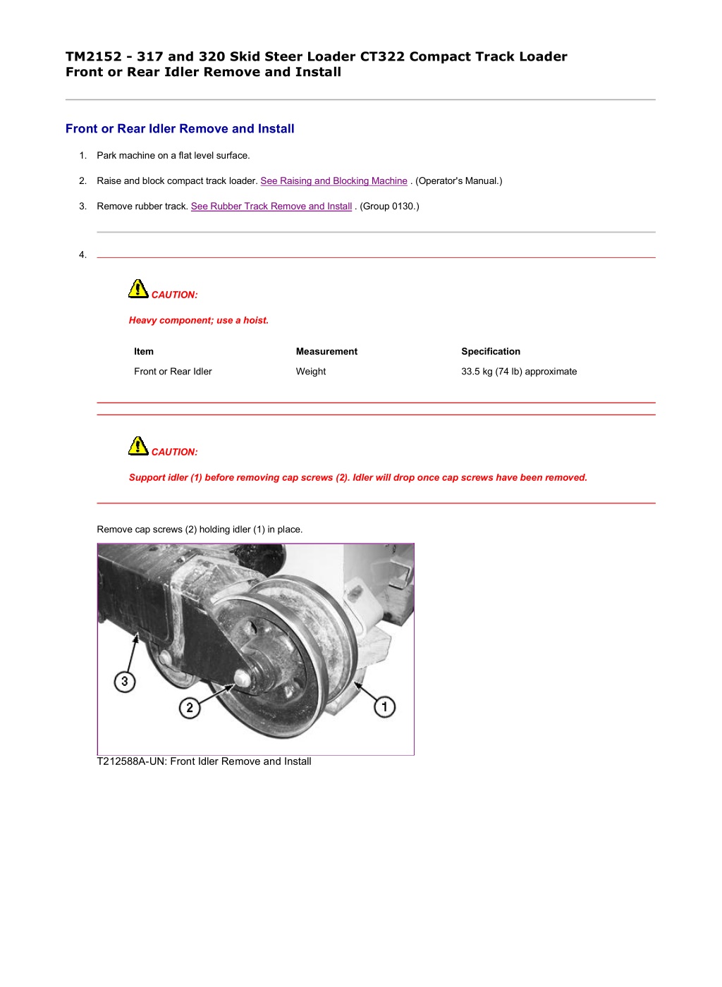
1/2 TM2152 - 317 and 320 Skid Steer Loader CT322 Compact Track Loader Front or Rear Idler Remove and Install Front or Rear Idler Remove and Install 1. Park machine on a flat level surface. 2. Raise and block compact track loader. See Raising and Blocking Machine . (Operator's Manual.) 3. Remove rubber track. See Rubber Track Remove and Install . (Group 0130.) 4. CAUTION: Heavy component; use a hoist. Item Measurement Specification Front or Rear Idler Weight 33.5 kg (74 lb) approximate CAUTION: Support idler (1) before removing cap screws (2). Idler will drop once cap screws have been removed. Remove cap screws (2) holding idler (1) in place. T212588A-UN: Front Idler Remove and Install file:///C:/ProgramData/Service%20ADVISOR/Temp/TM2152_09001faa8026... 2019/11/23
2/2 T212249A-UN: Rear Idler Remove and Install LEGEND: 1 - Idler 2 - Cap Screw (2 used) 3 - Track Frame 5. Using a shop hoist, remove idler from track frame. 6. Repair or replace as necessary. See Front or Rear Idler Disassemble and Assemble . (Group 0130.) 7. Apply threadlock and sealer (medium strength) to threads of cap screws. 8. Install rear idler into track frame. 9. Tighten cap screws. Item Measurement Specification Front or Rear Idler Cap Screw Torque 592 696 N m (437 513 lb-ft) 10. Install rubber track. See Rubber Track Remove and Install . (Group 0130.) 11. Adjust track sag. See Check and Adjust Track Sag . (Group 9020-25.) 12. Raise machine and remove blocking. See Raising and Blocking Machine . (Operator's Manual.) LOCTITE is a trademark of Loctite Corp. KK70125,000009A-19-20081111 file:///C:/ProgramData/Service%20ADVISOR/Temp/TM2152_09001faa8026... 2019/11/23
1/2 TM2152 - 317 and 320 Skid Steer Loader CT322 Compact Track Loader Front or Rear Idler Disassemble and Assemble Front or Rear Idler Disassemble and Assemble T210902-UN: Front or Rear Idler LEGEND: 1 - Snap Ring (2 used) 2 - Plug 3 - Collar (with Plug Hole) 4 - Metal Face Seal (2 used) 5 - O-Ring (2 used) 6 - Axle Shaft 7 - Bushing (2 used) 8 - Idler 9 - Collar 1. CAUTION: Heavy component; use a hoist. Item Measurement Specification Front or Rear Idler Weight 33.5 kg (74 lb) approximate Remove plug (2) and drain oil from idler. 2. Remove snap rings (1) from both ends of axle shaft (6). 3. Press axle shaft from idler (8). 4. Press remaining collar (9) from axle shaft. 5. NOTE: If bushings (7) are worn or damaged complete idler must be replaced. Inspect idler bushings (7) and axle shaft. Replace idler if bushings or axle shaft are worn or damaged. 6. IMPORTANT: Metal face seals can be reused if they are not worn or damaged. A used seal must be kept together as a set because of wear patterns on seal ring face. Remove metal face seals (4) from idler and collar. Keep seal rings together as a matched set with seal ring faces together to protect surfaces. 7. Inspect metal face seals. See Inspect Metal Face Seals . (Group 0130.) For seals that will be reused, put a piece of cardboard between seal rings to protect seal face. 8. Remove O-rings (5) from axle shaft. file:///C:/ProgramData/Service%20ADVISOR/Temp/TM2152_09001faa8026... 2019/11/23
https://www.ebooklibonline.com Hello dear friend! Thank you very much for reading. Enter the link into your browser. The full manual is available for immediate download. https://www.ebooklibonline.com
2/2 9. Install new O-rings on axle shaft. 10. Install snap ring on one end of axle shaft. 11. Tap axle shaft into collar (9). 12. IMPORTANT: Metal face seal O-rings and seat surfaces for O-rings must be clean, dry, and oil free so O-rings do not slip when roller is turning. Thoroughly clean O-ring and seat surfaces using volatile, non-petroleum base solvent and lint-free tissues. 13. Wipe finger prints and foreign material off seal ring face using clean oil and lint-free tissues. 14. Apply a thin film of oil to each seal ring face. 15. Install metal face seals in collars and idler. Apply equal pressure with fingers at four equally spaced points on seal face. Seal must pop down into place so O-ring is tight against seal bore. A volatile, non-petroleum base solvent or talcum powder may be used as a lubricant. 16. Tap axle shaft into idler. 17. Install collar (3) on axle shaft. 18. Support axle shaft and press on collar (3) to install snap ring. 19. Fill idler with 225 mL (7.6 oz) of SAE 80W-90 gear oil meeting API Service GL-5. Use graduated beaker or syringe to fill idler housing. Item Measurement Specification Front or Rear Idler Idler Gear Oil Capacity 225 mL (7.6 oz) 20. Clean threads of plug. Apply cure primer. 21. Apply pipe sealant to plug threads. Install and tighten plug. Item Measurement Specification Front or Rear Idler Plug Torque 21 26 N m (16 19 lb-ft.) LOCTITE is a trademark of Loctite Corp. KK70125,000009B-19-20080208 file:///C:/ProgramData/Service%20ADVISOR/Temp/TM2152_09001faa8026... 2019/11/23
1/2 TM2152 - 317 and 320 Skid Steer Loader CT322 Compact Track Loader Test Front or Rear Idler for Leakage Test Front or Rear Idler for Leakage T213175A-UN: Idler Oil Leakage Test Components LEGEND: 1 - Air Pressure Regulator 2 - Snubber (Needle) Valve 3 - Pressure Gauge 4 - Adapter Fittings and Hose to Connect to Track Roller 1. CAUTION: Heavy component; use a hoist. Item Measurement Specification Front or Rear Idler Weight 33.5 kg (74 lb) approximate Hold axle assembly and rotate idler several turns to seat metal face seals. 2. Remove plug. 3. Install parts (1 4). 4. Slowly pressurize oil cavity using air. Item Measurement Specification Front or Rear Idler Oil Cavity Air Test Pressure 160 kPa (1.6 bar) (23 psi) 5. Close valve and wait for a minimum of 30 seconds. Check for oil leakage. Check gauge to see if air pressure has decreased. 6. If there is leakage, disassemble idler and replace parts as necessary. See Front or Rear Idler Disassemble and Assemble . (Group 0130.) 7. Clean threads of plug. Apply cure primer. 8. Apply pipe sealant to threads. Install plug. Item Measurement Specification file:///C:/ProgramData/Service%20ADVISOR/Temp/TM2152_09001faa8026... 2019/11/23
2/2 Front or Rear Idler Plug Torque 21 26 N m (16 19 lb-ft.) LOCTITE is a trademark of Loctite Corp. KK70125,000009C-19-20080208 file:///C:/ProgramData/Service%20ADVISOR/Temp/TM2152_09001faa8026... 2019/11/23
1/2 TM2152 - 317 and 320 Skid Steer Loader CT322 Compact Track Loader Front Idler Yoke Assembly Remove and Install Front Idler Yoke Assembly Remove and Install 1. Park machine on a flat level surface. 2. Raise and block compact track loader. See Raising and Blocking Machine . (Operator's Manual.) 3. Remove rubber track. See Rubber Track Remove and Install . (Group 0130.) 4. CAUTION: Heavy component; use a hoist. Item Measurement Specification Front Idler Yoke Assembly Weight 86 kg (190 lb) approximate CAUTION: The front idler yoke assembly may be under spring force from track adjuster and can be pushed out from track frame. Make sure area in front of idler is clear. T212247A-UN: Front Idler Yoke Assembly Remove and Install LEGEND: 1 - Front Idler Yoke Assembly 2 - Track Frame Using a shop hoist, slide front idler yoke assembly (1) forward and remove from track frame (2). 5. Repair or replace parts as necessary. 6. Clean and apply grease to sliding surfaces inside track frame. 7. Install front idler yoke assembly into track frame. file:///C:/ProgramData/Service%20ADVISOR/Temp/TM2152_09001faa8020... 2019/11/23
2/2 8. Install rubber track. See Rubber Track Remove and Install . (Group 0130.) 9. Adjust track sag. See Check and Adjust Track Sag . (Group 9020-25.) 10. Raise machine and remove blocking. See Raising and Blocking Machine . (Operator's Manual.) KK70125,000005F-19-20081106 file:///C:/ProgramData/Service%20ADVISOR/Temp/TM2152_09001faa8020... 2019/11/23
1/2 TM2152 - 317 and 320 Skid Steer Loader CT322 Compact Track Loader Track Adjuster and Recoil Spring Assembly Remove and Install Track Adjuster and Recoil Spring Assembly Remove and Install 1. Park machine on a flat level surface. 2. Raise and block compact track loader. See Raising and Blocking Machine . (Operator's Manual.) 3. Remove rubber track. See Rubber Track Remove and Install . (Group 0130.) 4. Remove front idler yoke assembly. See Front Idler Yoke Assembly Remove and Install . (Group 0130.) 5. CAUTION: Spring or rod may break if dropped while handling, transporting or disassembling. Nicks or weld craters in spring and rod assembly can cause stress concentration resulting in a weak spot. Weak spots may result in immediate or eventual failure creating a risk of personal injury. Put a heavy protective covering around spring assembly when handling, transporting, or disassembling. CAUTION: Heavy component; use a hoist. Item Measurement Specification Track Adjuster and Recoil Spring Assembly Weight 31.8 kg (70 lb) approximate T212253A-UN: Track Adjuster and Recoil Spring Assembly Remove and Install LEGEND: 1 - Track Adjuster and Recoil Spring Assembly 2 - Track Frame 3 - Track Adjuster Valve 4 - Access Hole Slide track adjuster (1) and recoil spring assembly out of track frame (2). 6. Repair or replace parts as necessary. file:///C:/ProgramData/Service%20ADVISOR/Temp/TM2152_09001faa8026... 2019/11/23
2/2 7. Slide track adjuster and recoil spring assembly into track frame and push into place until track adjuster valve (3) is centered in access hole (4) in track frame. 8. Install front idler yoke assembly. See Front Idler Yoke Assembly Remove and Install . (Group 0130.) 9. Install rubber track. See Rubber Track Remove and Install . (Group 0130.) 10. Adjust track sag. See Check and Adjust Track Sag . (Group 9020-25.) 11. Raise machine and remove blocking. See Raising and Blocking Machine . (Operator's Manual.) KK70125,000009D-19-20081111 file:///C:/ProgramData/Service%20ADVISOR/Temp/TM2152_09001faa8026... 2019/11/23
1/4 TM2152 - 317 and 320 Skid Steer Loader CT322 Compact Track Loader Track Adjuster Recoil Spring Remove and Install Track Adjuster Recoil Spring Remove and Install 1. Remove track adjuster and recoil spring assembly from machine. See Track Adjuster and Recoil Spring Assembly Remove and Install . (Group 0130.) 2. T213238A-UN: Recoil Spring LEGEND: 1 - Cylinder Shaft 2 - Nut 3 - Retainer Plate 4 - Recoil Spring 5 - Cylinder Mark position of spring pin hole on nut (2) and cylinder shaft (1) to aid in assembly. 3. Remove spring pin (6) from nut on track adjuster and recoil spring assembly. 4. CAUTION: Spring or rod may break if dropped while handling, transporting or disassembling. Nicks or weld craters in spring and rod assembly can cause stress concentration resulting in a weak spot. Weak spots may result in immediate or eventual failure creating a risk of personal injury. Put a heavy protective covering around spring assembly when handling, transporting, or disassembling track adjuster. A compression tool must be used for disassembly and assembly because of the extreme preload on spring. CAUTION: Heavy component; use a hoist. Item Measurement Specification ST4920 Track Recoil Spring Tool Weight 225 kg (496 lb) approximate Track Adjuster and Recoil Spring Assembly Weight 31.8 kg (70 lb) approximate file:///C:/ProgramData/Service%20ADVISOR/Temp/TM2152_09001faa8026... 2019/11/23
2/4 T212514-UN: ST4920 Track Recoil Spring Tool LEGEND: 7 - ST4920 Track Recoil Spring Tool 8 - Jack 9 - Nut (4 used) 10 - Top Plate Place an 18-t (20-ton) jack (8) on bottom of ST4920 Track Recoil Spring Tool (7). See ST4920 Track Recoil Spring Disassembly and Assembly Tool for instruction to make tool. (Group 9900.) NOTE: It is not necessary to remove recoil spring to replace seals on piston rod. See Track Adjuster Cylinder Disassemble and Assemble . (Group 0130.) 5. Remove nuts (9). Remove top plate (10). file:///C:/ProgramData/Service%20ADVISOR/Temp/TM2152_09001faa8026... 2019/11/23
3/4 6. T213239A-UN: ST4920 Track Recoil Spring Tool LEGEND: 11 - Spacer 12 - DFT1087 Track Recoil Spring Guard Put track adjuster and recoil spring assembly in ST4920 Track Recoil Spring Tool with cylinder end on spacer (11). 7. Install DFT1087 Track Recoil Spring Guard (12). See DFT1087 Track Recoil Spring Disassembly and Assembly Guard Tool for instructions to make tool. (Group 9900.) 8. Install top plate with smallest opening to allow access to nut (2). 9. T212515A-UN: ST4920 Track Recoil Spring Tool LEGEND: 2 - Nut 9 - Nut (4 used) 10 - Top Plate file:///C:/ProgramData/Service%20ADVISOR/Temp/TM2152_09001faa8026... 2019/11/23
4/4 12 - DFT1087 Track Recoil Spring Guard Hand tighten nuts (9) so top plate (10) is tight against retainer plate (3). 10. Raise upper half of DFT1087 Track Recoil Spring Guard. Tighten T-handles. 11. Operate jack to compress recoil spring (4) just enough so nut (2) can be removed. 12. Lower jack ram to release spring force. 13. Remove nuts (9) and top plate to remove track adjuster and recoil spring assembly from ST4920 Track Recoil Spring Tool. 14. If disassembly of track adjuster cylinder is necessary, see Track Adjuster Cylinder Disassemble and Assemble . (Group 0130.) 15. Repair or replace parts as necessary. 16. Place track adjuster cylinder in ST4920 Track Recoil Spring Tool with cylinder end on spacer (11). 17. Install spring retainer plate on recoil spring. 18. Install DFT1087 Track Recoil Spring Guard. 19. Install top plate. Install and hand tighten nuts (9). 20. Raise upper half of DFT1087 Track Recoil Spring Guard. Tighten T-handles. 21. Operate jack to compress spring. 22. Install nut (2) so holes for spring pin are aligned in nut and cylinder shaft. 23. Install spring pin in nut (2). 24. Lower jack ram to relieve pressure. 25. Remove nuts (9) and top plate. 26. Remove track adjuster and recoil spring assembly from ST4920 Track Recoil Spring Tool. KK70125,000009E-19-20080208 file:///C:/ProgramData/Service%20ADVISOR/Temp/TM2152_09001faa8026... 2019/11/23
1/2 TM2152 - 317 and 320 Skid Steer Loader CT322 Compact Track Loader Track Adjuster Cylinder Disassemble and Assemble Track Adjuster Cylinder Disassemble and Assemble CAUTION: Spring or rod may break if dropped while handling, transporting or disassembling. Nicks or weld craters in spring and rod assembly can cause stress concentration resulting in a weak spot. Weak spots may result in immediate or eventual failure of spring or rod creating a risk of personal injury. Put a heavy protective covering around spring assembly when handling, transporting, or disassembling. A compression tool must be used for disassembly and assembly because of the extreme preload on spring. NOTE: It is not necessary to remove recoil spring to replace cylinder seals (2 and 4). CAUTION: Heavy component; use a hoist. Item Measurement Specification Track Adjuster and Recoil Spring Assembly Weight 31.8 kg (70 lb) approximate 1. T213214A-UN: Track Adjuster Cylinder LEGEND: 1 - Piston Rod 2 - Outer Seal 3 - Seal Retaining Ring 4 - Inner Seal 5 - Cylinder 6 - Track Adjuster Valve Remove track adjuster and recoil spring assembly from machine. See Track Adjuster and Recoil Spring Assembly Remove and Install . (Group 0130.) file:///C:/ProgramData/Service%20ADVISOR/Temp/TM2152_09001faa8026... 2019/11/23
Suggest: If the above button click is invalid. Please download this document first, and then click the above link to download the complete manual. Thank you so much for reading
2/2 2. Remove recoil spring, if necessary. See Track Adjuster Recoil Spring Remove and Install . (Group 0130.) 3. Tighten track adjuster valve (6). 4. Pump cylinder (5) with grease to remove piston rod (1) from cylinder. 5. Clean out excess grease from cylinder to access seals in cylinder end. 6. T213208A-UN: Cylinder Seals LEGEND: 2 - Outer Seal 3 - Seal Retaining Ring 4 - Inner Seal Remove outer seal (2) from cylinder. 7. Remove seal retaining ring (3) from inner seal (4) before removing seal from cylinder. 8. Repair or replace parts as necessary. 9. Install inner seal in cylinder with retaining ring groove facing outward. 10. Install seal retaining ring into groove of inner seal. 11. Install outer seal in cylinder. 12. Loosen track adjuster valve. 13. Apply grease to piston rod and install in cylinder. 14. Completely compress piston rod. 15. Tighten track adjuster valve. 16. Install recoil spring, if necessary. See Track Adjuster Recoil Spring Remove and Install . (Group 0130.) 17. Install track adjuster and recoil spring assembly in machine. See Track Adjuster and Recoil Spring Assembly Remove and Install . (Group 0130.) KK70125,000009F-19-20080208 file:///C:/ProgramData/Service%20ADVISOR/Temp/TM2152_09001faa8026... 2019/11/23
https://www.ebooklibonline.com Hello dear friend! Thank you very much for reading. Enter the link into your browser. The full manual is available for immediate download. https://www.ebooklibonline.com