Caterpillar Cat D5K LGP TRACK-TYPE TRACTOR (Prefix JLF) Service Repair Manual Instant Download (JLF00001 and up)
Please open the website below to get the complete manualnn// n

Download Presentation

Please find below an Image/Link to download the presentation.
The content on the website is provided AS IS for your information and personal use only. It may not be sold, licensed, or shared on other websites without obtaining consent from the author. Download presentation by click this link. If you encounter any issues during the download, it is possible that the publisher has removed the file from their server.
E N D
Presentation Transcript
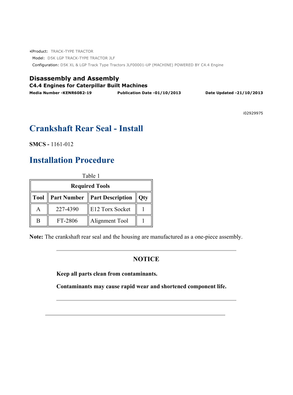
D5K XL & LGP Track Type Tractors JLF00001-UP (MACHINE) POWERED BY C4... 1/4 Product: TRACK-TYPE TRACTOR Model: D5K LGP TRACK-TYPE TRACTOR JLF Configuration: D5K XL & LGP Track Type Tractors JLF00001-UP (MACHINE) POWERED BY C4.4 Engine Disassembly and Assembly C4.4 Engines for Caterpillar Built Machines Media Number -KENR6082-19 Publication Date -01/10/2013 Date Updated -21/10/2013 i02929975 Crankshaft Rear Seal - Install SMCS - 1161-012 Installation Procedure Table 1 Required Tools Tool Part Number Part Description Qty A 227-4390 E12 Torx Socket 1 B FT-2806 Alignment Tool 1 Note: The crankshaft rear seal and the housing are manufactured as a one-piece assembly. NOTICE Keep all parts clean from contaminants. Contaminants may cause rapid wear and shortened component life. https://127.0.0.1/sisweb/sisweb/techdoc/techdoc_print_page.jsp?returnurl=/sis... 2022/5/21
D5K XL & LGP Track Type Tractors JLF00001-UP (MACHINE) POWERED BY C4... 2/4 Illustration 1 g01258105 Illustration 2 g01255709 Typical example 1. Ensure that crankshaft flange (1) is clean, dry and free from damage. 2. Ensure that the face of the cylinder block and the bridge piece are clean and dry. 3. A new crankshaft rear seal is supplied with a plastic sleeve (3). Ensure that the plastic sleeve is squarely installed within crankshaft rear seal (2). Note: The plastic sleeve is included in order to protect the lip of the seal as the seal is pushed over the crankshaft flange. Note: Do not lubricate the crankshaft rear seal or the crankshaft flange. The crankshaft rear seal must be installed dry. https://127.0.0.1/sisweb/sisweb/techdoc/techdoc_print_page.jsp?returnurl=/sis... 2022/5/21
D5K XL & LGP Track Type Tractors JLF00001-UP (MACHINE) POWERED BY C4... 3/4 4. Align plastic sleeve (3) with crankshaft flange (1). Ensure that the plastic sleeve is engaged onto the crankshaft flange. Push new crankshaft rear seal (2) squarely onto the crankshaft flange. During this process, the plastic sleeve will be forced out of the crankshaft rear seal. Discard the plastic sleeve. 5. Align the two molded locators on crankshaft rear seal (2) with the holes in the cylinder block. Ensure that the crankshaft rear seal is seated against the cylinder block. Illustration 3 g01258357 Tightening sequence for the crankshaft rear seal 6. Install torx screws (4) finger tight. Note: Do not install torx screws to Positions (X) at this stage. 7. Install Tooling (B) to crankshaft rear seal (2) and to crankshaft flange (1). 8. Use Tooling (A) in order to tighten torx screws (4) to a torque of 22 N m (16 lb ft). Tighten torx screws (4) in the sequence that is shown in Illustration 3. 9. Remove Tooling (B). 10. Install remaining torx screws (4) to Positions (X). Use Tooling (A) in order to tighten the torx screws to a torque of 22 N m (16 lb ft). Refer to Illustration 3. https://127.0.0.1/sisweb/sisweb/techdoc/techdoc_print_page.jsp?returnurl=/sis... 2022/5/21
https://www.ebooklibonline.com Hello dear friend! Thank you very much for reading. Enter the link into your browser. The full manual is available for immediate download. https://www.ebooklibonline.com
D5K XL & LGP Track Type Tractors JLF00001-UP (MACHINE) POWERED BY C4... 4/4 End By: a. Install the flywheel. Refer to Disassembly and Assembly, "Flywheel - Install". https://127.0.0.1/sisweb/sisweb/techdoc/techdoc_print_page.jsp?returnurl=/sis... 2022/5/21
D5K XL & LGP Track Type Tractors JLF00001-UP (MACHINE) POWERED BY C4... 1/6 Product: TRACK-TYPE TRACTOR Model: D5K LGP TRACK-TYPE TRACTOR JLF Configuration: D5K XL & LGP Track Type Tractors JLF00001-UP (MACHINE) POWERED BY C4.4 Engine Disassembly and Assembly C4.4 Engines for Caterpillar Built Machines Media Number -KENR6082-19 Publication Date -01/10/2013 Date Updated -21/10/2013 i02930000 Flywheel Housing - Remove and Install SMCS - 1157-010 Removal Procedure Table 1 Required Tools Tool Part Number Part Description Qty Guide Stud M10 by 100 mm A - 2 Start By: a. Remove the flywheel. Refer to Disassembly and Assembly, "Flywheel - Remove". NOTICE Keep all parts clean from contaminants. Contaminants may cause rapid wear and shortened component life. https://127.0.0.1/sisweb/sisweb/techdoc/techdoc_print_page.jsp?returnurl=/sis... 2022/5/21
D5K XL & LGP Track Type Tractors JLF00001-UP (MACHINE) POWERED BY C4... 2/6 Illustration 1 g01470403 Typical example 1. Remove the bolts from Position (X) from flywheel housing (1). 2. Install Tooling (A) into Position (X) on flywheel housing (1). 3. Install a suitable lifting device to the flywheel housing in order to support the flywheel housing. The flywheel housing weighs approximately 30 kg (66 lb). https://127.0.0.1/sisweb/sisweb/techdoc/techdoc_print_page.jsp?returnurl=/sis... 2022/5/21
D5K XL & LGP Track Type Tractors JLF00001-UP (MACHINE) POWERED BY C4... 3/6 Illustration 2 g01763013 Typical example 4. Remove bolts (2) and remaining bolts (3) from flywheel housing (1). 5. Use the lifting device in order to remove flywheel housing (1) from the cylinder block. Illustration 3 g01470418 https://127.0.0.1/sisweb/sisweb/techdoc/techdoc_print_page.jsp?returnurl=/sis... 2022/5/21
D5K XL & LGP Track Type Tractors JLF00001-UP (MACHINE) POWERED BY C4... 4/6 Typical example 6. If the engine has an aluminum oil pan, remove dust seal (5). 7. If necessary, remove dowels (4) from the cylinder block. Installation Procedure Table 2 Required Tools Tool Part Number Part Description Qty Guide Bolt M10 by 100 mm A - 2 B 8T-5096 Dial Indicator Group 1 NOTICE Keep all parts clean from contaminants. Contaminants may cause rapid wear and shortened component life. 1. Ensure that the flywheel housing is clean and free from damage. If necessary, replace the flywheel housing. Illustration 4 g01244056 Typical example https://127.0.0.1/sisweb/sisweb/techdoc/techdoc_print_page.jsp?returnurl=/sis... 2022/5/21
D5K XL & LGP Track Type Tractors JLF00001-UP (MACHINE) POWERED BY C4... 5/6 2. Inspect crankshaft rear seal (6) for leaks. If there are any oil leaks, replace the crankshaft rear seal. Refer to Disassembly and Assembly, "Crankshaft Rear Seal - Remove" and refer to Disassembly and Assembly, "Crankshaft Rear Seal - Install". 3. Clean the rear face of the cylinder block. If necessary, install dowels (4) to the cylinder block. 4. Install Tooling (A) to the cylinder block. 5. Install dust seal (5). Illustration 5 g01763034 Typical example 6. Install a suitable lifting device to the flywheel housing. The flywheel housing weighs approximately 30 kg (66 lb). 7. Use the lifting device to align flywheel housing (1) with Tooling (A). Install the flywheel housing to the cylinder block. 8. Install bolts (2) and bolts (3) finger tight. 9. Remove Tooling (A). Install remaining bolts (3). 10. Tighten bolts (3) to a torque of 63 N m (46 lb ft). 11. Tighten bolts (2) to a torque of 75 N m (55 lb ft). https://127.0.0.1/sisweb/sisweb/techdoc/techdoc_print_page.jsp?returnurl=/sis... 2022/5/21
D5K XL & LGP Track Type Tractors JLF00001-UP (MACHINE) POWERED BY C4... 6/6 12. Use Tooling (B) to check the alignment of the flywheel housing with the crankshaft. Refer to Systems Operation, Testing and Adjusting, "Flywheel Housing - Inspect". End By: a. Install the flywheel. Refer to Disassembly and Assembly, "Flywheel - Install". https://127.0.0.1/sisweb/sisweb/techdoc/techdoc_print_page.jsp?returnurl=/sis... 2022/5/21
D5K XL & LGP Track Type Tractors JLF00001-UP (MACHINE) POWERED BY C4... 1/4 Product: TRACK-TYPE TRACTOR Model: D5K LGP TRACK-TYPE TRACTOR JLF Configuration: D5K XL & LGP Track Type Tractors JLF00001-UP (MACHINE) POWERED BY C4.4 Engine Disassembly and Assembly C4.4 Engines for Caterpillar Built Machines Media Number -KENR6082-19 Publication Date -01/10/2013 Date Updated -21/10/2013 i02929973 Crankshaft Pulley - Remove and Install - Engines With an Automatic Belt Tensioner SMCS - 1205-010 Removal Procedure Start By: a. Remove the alternator belt. Refer to Disassembly and Assembly, "Alternator Belt - Remove and Install". NOTICE Keep all parts clean from contaminants. Contaminants may cause rapid wear and shortened component life. https://127.0.0.1/sisweb/sisweb/techdoc/techdoc_print_page.jsp?returnurl=/sis... 2022/5/21
D5K XL & LGP Track Type Tractors JLF00001-UP (MACHINE) POWERED BY C4... 2/4 Illustration 1 g01249049 1. Use a suitable tool in order to prevent the crankshaft from rotating. Remove bolts (1). 2. Remove thrust block (2). 3. Carefully remove the assembly of the crankshaft pulley from the crankshaft. 4. Follow Step 4.a through Step 4.b in order to disassemble the crankshaft pulley. a. Remove bolts (5). b. Remove crankshaft pulley (4) from crankshaft adapter (3). Installation Procedure NOTICE Keep all parts clean from contaminants. Contaminants may cause rapid wear and shortened component life. https://127.0.0.1/sisweb/sisweb/techdoc/techdoc_print_page.jsp?returnurl=/sis... 2022/5/21
D5K XL & LGP Track Type Tractors JLF00001-UP (MACHINE) POWERED BY C4... 3/4 1. Ensure that the crankshaft adapter, the pulley and the thrust block are clean and free from damage. Replace any components that are damaged. Illustration 2 g01249049 2. If necessary, follow Step 2.a through Step 2.b in order to assemble the crankshaft pulley. a. Install crankshaft pulley (4) to crankshaft adapter (3). b. Install bolts (5) to the assembly of the crankshaft pulley, and the crankshaft adapter. The bolts should be evenly spaced. c. Tighten the bolts to a torque of 78 N m (58 lb ft). 3. Ensure that the front of the crankshaft is clean and free from damage. Install the assembly of crankshaft pulley (3) to the crankshaft. https://127.0.0.1/sisweb/sisweb/techdoc/techdoc_print_page.jsp?returnurl=/sis... 2022/5/21
D5K XL & LGP Track Type Tractors JLF00001-UP (MACHINE) POWERED BY C4... 4/4 Illustration 3 g01471632 4. Align the holes in the thrust block with the holes in the crankshaft. Note: Ensure chamfered Holes (X) in the thrust block. Face toward the front of the engine. 5. Install thrust block (2) to the assembly of the crankshaft pulley. 6. Install bolts (1) to thrust block (2). 7. Use a suitable tool in order to prevent the crankshaft from rotating. Tighten the bolts to a torque of 115 N m (85 lb ft). 8. Repeat Step 7 in order to ensure correct torque. End By: a. Install the alternator belt. Refer to Disassembly and Assembly, "Alternator Belt - Remove and Install". https://127.0.0.1/sisweb/sisweb/techdoc/techdoc_print_page.jsp?returnurl=/sis... 2022/5/21
D5K XL & LGP Track Type Tractors JLF00001-UP (MACHINE) POWERED BY C4... 1/3 Product: TRACK-TYPE TRACTOR Model: D5K LGP TRACK-TYPE TRACTOR JLF Configuration: D5K XL & LGP Track Type Tractors JLF00001-UP (MACHINE) POWERED BY C4.4 Engine Disassembly and Assembly C4.4 Engines for Caterpillar Built Machines Media Number -KENR6082-19 Publication Date -01/10/2013 Date Updated -21/10/2013 i02929974 Crankshaft Pulley - Remove and Install - Engines Without an Automatic Belt Tensioner SMCS - 1205-010 Removal Procedure Start By: a. Remove the V-Belts. Refer to Disassembly and Assembly, "V-Belts - Remove and Install". NOTICE Keep all parts clean from contaminants. Contaminants may cause rapid wear and shortened component life. https://127.0.0.1/sisweb/sisweb/techdoc/techdoc_print_page.jsp?returnurl=/sis... 2022/5/21
D5K XL & LGP Track Type Tractors JLF00001-UP (MACHINE) POWERED BY C4... 2/3 Illustration 1 g01255707 1. Use a suitable tool in order to prevent the crankshaft from rotating. Remove bolts (1). 2. Remove thrust block (2). 3. Carefully remove crankshaft pulley (3) from the crankshaft. Installation Procedure Illustration 2 g01255707 https://127.0.0.1/sisweb/sisweb/techdoc/techdoc_print_page.jsp?returnurl=/sis... 2022/5/21
D5K XL & LGP Track Type Tractors JLF00001-UP (MACHINE) POWERED BY C4... 3/3 Illustration 3 g01471632 1. Ensure that the crankshaft pulley and the thrust block are clean and free from damage. Replace any components that are damaged. 2. Ensure that the front of the crankshaft is clean and free from damage. Install crankshaft pulley (3) to the crankshaft. 3. Align the holes in the thrust block with the holes in the crankshaft. Note: Ensure that chamfered Holes (X) in the thrust block face toward the front of the engine. 4. Install thrust block (2) to the crankshaft pulley. 5. Install bolts (1) to thrust block (2). 6. Use a suitable tool in order to prevent the crankshaft from rotating. Tighten the bolts to a torque of 115 N m (85 lb ft). 7. Repeat Step 6 in order to ensure correct torque. End By: a. Install the V-Belts. Refer to Disassembly and Assembly, "V-Belts - Remove and Install". https://127.0.0.1/sisweb/sisweb/techdoc/techdoc_print_page.jsp?returnurl=/sis... 2022/5/21
D5K XL & LGP Track Type Tractors JLF00001-UP (MACHINE) POWERED BY C4... 1/3 Product: TRACK-TYPE TRACTOR Model: D5K LGP TRACK-TYPE TRACTOR JLF Configuration: D5K XL & LGP Track Type Tractors JLF00001-UP (MACHINE) POWERED BY C4.4 Engine Disassembly and Assembly C4.4 Engines for Caterpillar Built Machines Media Number -KENR6082-19 Publication Date -01/10/2013 Date Updated -21/10/2013 i02929969 Crankshaft Front Seal - Remove and Install SMCS - 1160-010 Removal Procedure Table 1 Required Tools Tool Part Number Part Description Qty A 1P-2320 Combination Puller 1 Start By: a. Remove the crankshaft pulley. Refer to Disassembly and Assembly, "Crankshaft Pulley - Remove and Install". NOTICE Keep all parts clean from contaminants. Contaminants may cause rapid wear and shortened component life. https://127.0.0.1/sisweb/sisweb/techdoc/techdoc_print_page.jsp?returnurl=/sis... 2022/5/21
D5K XL & LGP Track Type Tractors JLF00001-UP (MACHINE) POWERED BY C4... 2/3 Illustration 1 g01266942 1. Install the legs of Tooling (A) behind crankshaft front seal (1). Install a suitable spacer (2) between Tooling (A) and crankshaft (3). Use Tooling (A) in order to pull the crankshaft front seal out of the front housing. Note: Do not damage the bore for the crankshaft front seal in the front housing. Installation Procedure Table 2 Required Tools Tool Part Number Part Description Qty B 9U-6210 Front Seal Installer 1 NOTICE Keep all parts clean from contaminants. Contaminants may cause rapid wear and shortened component life. 1. Ensure that the bore for the crankshaft front seal in the front housing is clean and free from damage. https://127.0.0.1/sisweb/sisweb/techdoc/techdoc_print_page.jsp?returnurl=/sis... 2022/5/21
D5K XL & LGP Track Type Tractors JLF00001-UP (MACHINE) POWERED BY C4... 3/3 Illustration 2 g01266453 Typical example 2. Assemble Tooling (B). 3. Align a new crankshaft front seal (1) to the front housing. 4. Use Tooling (B) to install crankshaft front seal (1). Ensure that the front face of the seal is installed to a depth of 9 0.2 mm (0.354 0.008 inch) into the front housing. 5. Remove Tooling (B) from the crankshaft. End By: a. Install the crankshaft pulley. Refer to Disassembly and Assembly, "Crankshaft Pulley - Remove and Install". https://127.0.0.1/sisweb/sisweb/techdoc/techdoc_print_page.jsp?returnurl=/sis... 2022/5/21
D5K XL & LGP Track Type Tractors JLF00001-UP (MACHINE) POWERED BY C4... 1/4 Product: TRACK-TYPE TRACTOR Model: D5K LGP TRACK-TYPE TRACTOR JLF Configuration: D5K XL & LGP Track Type Tractors JLF00001-UP (MACHINE) POWERED BY C4.4 Engine Disassembly and Assembly C4.4 Engines for Caterpillar Built Machines Media Number -KENR6082-19 Publication Date -01/10/2013 Date Updated -21/10/2013 i02930001 Front Cover - Remove and Install SMCS - 1166-010 Removal Procedure Start By: a. If the engine is equipped with a fan, remove the fan. Refer to Disassembly and Assembly, "Fan - Remove and Install". b. Remove the water pump. Refer to Disassembly and Assembly, "Water Pump - Remove". NOTICE Care must be taken to ensure that fluids are contained during performance of inspection, maintenance, testing, adjusting and repair of the product. Be prepared to collect the fluid with suitable containers before opening any compartment or disassembling any component containing fluids. Dispose of all fluids according to local regulations and mandates. NOTICE Keep all parts clean from contaminants. Contaminants may cause rapid wear and shortened component life. https://127.0.0.1/sisweb/sisweb/techdoc/techdoc_print_page.jsp?returnurl=/sis... 2022/5/21
D5K XL & LGP Track Type Tractors JLF00001-UP (MACHINE) POWERED BY C4... 2/4 Note: In order to remove the front cover, it is not necessary to remove the crankshaft pulley or the alternator. Illustration 1 g01258462 Typical example 1. Remove bolts (3), (4) and (5). Identify the positions of the different bolts. 2. Remove front cover (1) from the front housing. 3. Remove gasket (2) from front cover (1). Installation Procedure Table 1 Required Tools Tool Part Number Part Description Qty Guide Bolt M8 by 80 mm A - 2 NOTICE https://127.0.0.1/sisweb/sisweb/techdoc/techdoc_print_page.jsp?returnurl=/sis... 2022/5/21
D5K XL & LGP Track Type Tractors JLF00001-UP (MACHINE) POWERED BY C4... 3/4 Keep all parts clean from contaminants. Contaminants may cause rapid wear and shortened component life. Illustration 2 g01471654 Typical example 1. Thoroughly clean the face of the front housing. 2. If the original front cover is installed, follow Step 2.a and Step 2.b in order to install the gasket. a. Thoroughly clean the front cover. https://127.0.0.1/sisweb/sisweb/techdoc/techdoc_print_page.jsp?returnurl=/sis... 2022/5/21
Suggest: For more complete manuals. Please go to the home page. https://www.ebooklibonline.com If the above button click is invalid. Please download this document first, and then click the above link to download the complete manual. Thank you so much for reading
D5K XL & LGP Track Type Tractors JLF00001-UP (MACHINE) POWERED BY C4... 4/4 b. Install a new gasket (2) to front cover (1). Engage Locators (Y) into the holes in the front cover. 3. Install Tooling (A) into Holes (X) in the front housing. 4. Use Tooling (A) in order to position the front cover assembly onto the front housing. 5. Install bolts (3), (4) and (5) finger tight. Ensure that the different bolts are installed in the correct positions. 6. Loosely install the water pump assembly and remove Tooling (A). Refer to Disassembly and Assembly, "Water Pump - Install" for the correct procedure. 7. Tighten bolts (3), (4) and (5) to a torque of 22 N m (16 lb ft). 8. Tighten the bolts for the water pump to a torque of 22 N m (16 lb ft). End By: a. If the engine is equipped with a fan, install the fan. Refer to Disassembly and Assembly, "Fan - Remove and Install". https://127.0.0.1/sisweb/sisweb/techdoc/techdoc_print_page.jsp?returnurl=/sis... 2022/5/21
D5K XL & LGP Track Type Tractors JLF00001-UP (MACHINE) POWERED BY C4... 1/9 Product: TRACK-TYPE TRACTOR Model: D5K LGP TRACK-TYPE TRACTOR JLF Configuration: D5K XL & LGP Track Type Tractors JLF00001-UP (MACHINE) POWERED BY C4.4 Engine Disassembly and Assembly C4.4 Engines for Caterpillar Built Machines Media Number -KENR6082-19 Publication Date -01/10/2013 Date Updated -21/10/2013 i02930015 Gear Group (Front) - Remove and Install SMCS - 1206-010 Removal Procedure Table 1 Required Tools Tool Part Number Part Description Qty A(1) 9U-6198 Crankshaft Turning Tool 1 9U-7336 Housing 1 A(2) 5P-7305 Engine Turning Tool 1 B 230-6284 Timing Pin (Camshaft) 1 C 230-6283 Timing Pin (Crankshaft) 1 (1)The Crankshaft Turning Tool is used on the front pulley. (2)This Tool is used in the aperture for the electric starting motor. Start By: a. If the engine is equipped with an air compressor, remove the air compressor. Refer to Disassembly and Assembly, "Air Compressor - Remove and Install". b. If the engine is equipped with a vacuum pump, remove the vacuum pump. Refer to Disassembly and Assembly, "Vacuum Pump - Remove and Install". c. If the engine is equipped with an accessory drive, remove the accessory drive. Refer to Disassembly and Assembly, "Accessory Drive - Remove and Install". d. Remove the front cover. Refer to Disassembly and Assembly, "Front Cover - Remove and Install". https://127.0.0.1/sisweb/sisweb/techdoc/techdoc_print_page.jsp?returnurl=/sis... 2022/5/21
https://www.ebooklibonline.com Hello dear friend! Thank you very much for reading. Enter the link into your browser. The full manual is available for immediate download. https://www.ebooklibonline.com
")
")
")

")
")
")
")
")
")
")
")
")
")
")
")
")
")
")
")
")
")
")
")

")
")