Caterpillar Cat D3K2 LGP TRACK-TYPE TRACTOR (Prefix LT3) Service Repair Manual Instant Download (LT300001 and up)
Please open the website below to get the complete manualnn// n

Download Presentation

Please find below an Image/Link to download the presentation.
The content on the website is provided AS IS for your information and personal use only. It may not be sold, licensed, or shared on other websites without obtaining consent from the author. Download presentation by click this link. If you encounter any issues during the download, it is possible that the publisher has removed the file from their server.
E N D
Presentation Transcript
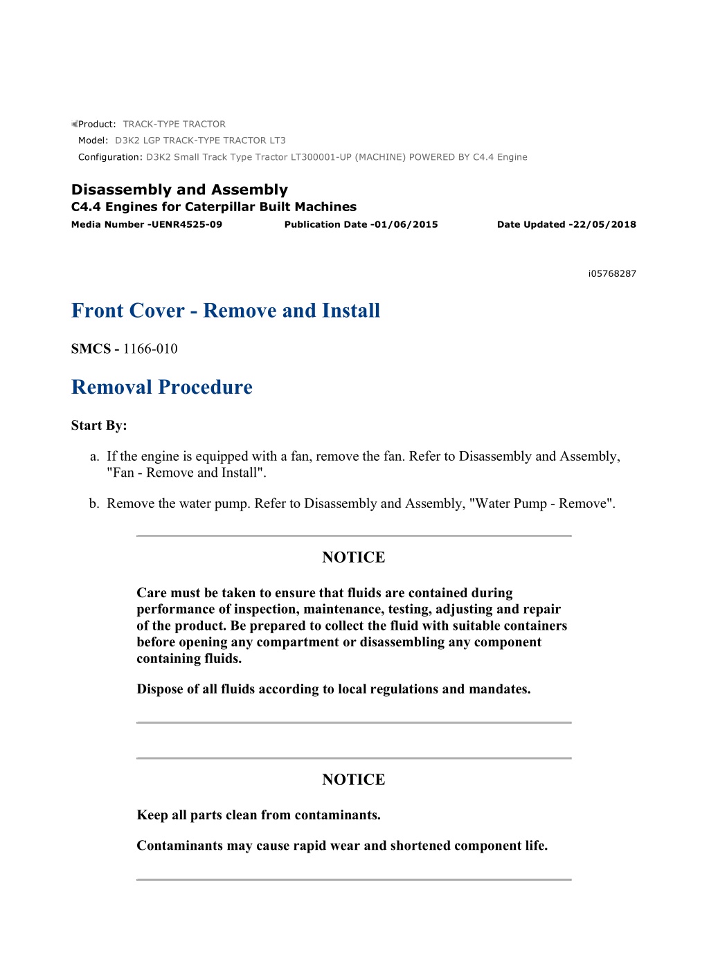
D3K2 Small Track Type Tractor LT300001-UP (MACHINE) POWERED BY C4.4 E... 1/4 Product: TRACK-TYPE TRACTOR Model: D3K2 LGP TRACK-TYPE TRACTOR LT3 Configuration: D3K2 Small Track Type Tractor LT300001-UP (MACHINE) POWERED BY C4.4 Engine Disassembly and Assembly C4.4 Engines for Caterpillar Built Machines Media Number -UENR4525-09 Publication Date -01/06/2015 Date Updated -22/05/2018 i05768287 Front Cover - Remove and Install SMCS - 1166-010 Removal Procedure Start By: a. If the engine is equipped with a fan, remove the fan. Refer to Disassembly and Assembly, "Fan - Remove and Install". b. Remove the water pump. Refer to Disassembly and Assembly, "Water Pump - Remove". NOTICE Care must be taken to ensure that fluids are contained during performance of inspection, maintenance, testing, adjusting and repair of the product. Be prepared to collect the fluid with suitable containers before opening any compartment or disassembling any component containing fluids. Dispose of all fluids according to local regulations and mandates. NOTICE Keep all parts clean from contaminants. Contaminants may cause rapid wear and shortened component life. https://127.0.0.1/sisweb/sisweb/techdoc/techdoc_print_page.jsp?returnurl=/sis... 2022/5/28
D3K2 Small Track Type Tractor LT300001-UP (MACHINE) POWERED BY C4.4 E... 2/4 Note: In order to remove the front cover, it is not necessary to remove the crankshaft pulley or the alternator. Illustration 1 g01258462 Typical example 1. Remove bolts (3), (4) and (5). Identify the positions of the different bolts. 2. Remove front cover (1) from the front housing. 3. Remove gasket (2) from front cover (1). Installation Procedure Table 1 Required Tools Tool Part Number Part Description Qty Guide Bolt M8 by 80 mm A - 2 NOTICE https://127.0.0.1/sisweb/sisweb/techdoc/techdoc_print_page.jsp?returnurl=/sis... 2022/5/28
D3K2 Small Track Type Tractor LT300001-UP (MACHINE) POWERED BY C4.4 E... 3/4 Keep all parts clean from contaminants. Contaminants may cause rapid wear and shortened component life. Illustration 2 g01471654 Typical example 1. Thoroughly clean the gasket surface of the front housing. 2. If the original front cover is to be reinstalled, follow Step 2.a and Step 2.b in order to install the gasket. a. Thoroughly clean the gasket surface of the front cover. https://127.0.0.1/sisweb/sisweb/techdoc/techdoc_print_page.jsp?returnurl=/sis... 2022/5/28
https://www.ebooklibonline.com Hello dear friend! Thank you very much for reading. Enter the link into your browser. The full manual is available for immediate download. https://www.ebooklibonline.com
D3K2 Small Track Type Tractor LT300001-UP (MACHINE) POWERED BY C4.4 E... 4/4 b. Install a new gasket (2) to front cover (1). Engage Locators (Y) into the holes in the front cover. 3. Install Tooling (A) into Holes (X) in the front housing. 4. Use Tooling (A) in order to position the front cover assembly onto the front housing. 5. Install bolts (3), (4) and (5) finger tight. Ensure that the different bolts are installed in the correct positions. 6. Loosely install the water pump assembly and remove Tooling (A). Refer to Disassembly and Assembly, "Water Pump - Install" for the correct procedure. 7. Tighten bolts (3), (4) and (5) to a torque of 22 N m (194.72 lb in). 8. Tighten the bolts for the water pump to a torque of 22 N m (194.72 lb in). End By: a. If the engine is equipped with a fan, install the fan. Refer to Disassembly and Assembly, "Fan - Remove and Install". https://127.0.0.1/sisweb/sisweb/techdoc/techdoc_print_page.jsp?returnurl=/sis... 2022/5/28
D3K2 Small Track Type Tractor LT300001-UP (MACHINE) POWERED BY C4.4 E... 1/10 Product: TRACK-TYPE TRACTOR Model: D3K2 LGP TRACK-TYPE TRACTOR LT3 Configuration: D3K2 Small Track Type Tractor LT300001-UP (MACHINE) POWERED BY C4.4 Engine Disassembly and Assembly C4.4 Engines for Caterpillar Built Machines Media Number -UENR4525-09 Publication Date -01/06/2015 Date Updated -22/05/2018 i05738612 Gear Group (Front) - Remove and Install SMCS - 1206-010 Removal Procedure Table 1 Required Tools Tool Part Number Part Description Qty A(1) 9U-6198 Crankshaft Turning Tool 1 9U-7336 Housing 1 A(2) 5P-7305 Engine Turning Tool 1 B 230-6284 Timing Pin (Camshaft) 1 C 230-6283 Timing Pin (Crankshaft) 1 (1)The Crankshaft Turning Tool is used on the front pulley. (2)This Tool is used in the aperture for the electric starting motor. Start By: a. If the engine is equipped with an air compressor, remove the air compressor. Refer to Disassembly and Assembly, "Air Compressor - Remove and Install". b. If the engine is equipped with a vacuum pump, remove the vacuum pump. Refer to Disassembly and Assembly, "Vacuum Pump - Remove and Install". c. If the engine is equipped with an accessory drive, remove the accessory drive. Refer to Disassembly and Assembly, "Accessory Drive - Remove and Install". d. Remove the front cover. Refer to Disassembly and Assembly, "Front Cover - Remove and Install". https://127.0.0.1/sisweb/sisweb/techdoc/techdoc_print_page.jsp?returnurl=/sis... 2022/5/28
D3K2 Small Track Type Tractor LT300001-UP (MACHINE) POWERED BY C4.4 E... 2/10 e. Remove the valve mechanism cover. Refer to Disassembly and Assembly, "Valve Mechanism Cover - Remove and Install". Note: Either Tooling (A) can be used. Use the Tooling that is most suitable. NOTICE Keep all parts clean from contaminants. Contaminants may cause rapid wear and shortened component life. NOTICE Care must be taken to ensure that fluids are contained during performance of inspection, maintenance, testing, adjusting and repair of the product. Be prepared to collect the fluid with suitable containers before opening any compartment or disassembling any component containing fluids. Dispose of all fluids according to local regulations and mandates. Note: Care must be taken in order to ensure that the fuel injection pump timing is not lost during the removal of the front gear group. Carefully follow the procedure in order to remove the gear group. 1. Use Tooling (A) in order to rotate the crankshaft so that number one piston is at the top center position on the compression stroke. Refer to Systems Operation, Testing and Adjusting, "Finding Top Centre Position for No.1 Piston". https://127.0.0.1/sisweb/sisweb/techdoc/techdoc_print_page.jsp?returnurl=/sis... 2022/5/28
D3K2 Small Track Type Tractor LT300001-UP (MACHINE) POWERED BY C4.4 E... 3/10 Illustration 1 g03662683 Typical example 2. Install Tooling (B) through hole (X) in camshaft gear (1) into the front housing. Use Tooling (B) in order to lock the camshaft in the correct position. Install Tooling (C) into hole (Y) in the front housing. Use Tooling (C) in order to lock the crankshaft in the correct position. Refer to Systems Operation, Testing and Adjusting, "Finding Top Centre Position for No.1 Piston". Note: Do not use excessive force to install Tooling (C). Do not use Tooling (C) to hold the crankshaft during repairs. https://127.0.0.1/sisweb/sisweb/techdoc/techdoc_print_page.jsp?returnurl=/sis... 2022/5/28
D3K2 Small Track Type Tractor LT300001-UP (MACHINE) POWERED BY C4.4 E... 4/10 Illustration 2 g01322693 Typical example 3. Loosen nuts (6) on all rocker arms (7). Unscrew adjusters (5) on all rocker arms (7) until all valves are fully closed. Note: Failure to ensure that ALL adjusters are fully unscrewed can result in contact between the valves and pistons. https://127.0.0.1/sisweb/sisweb/techdoc/techdoc_print_page.jsp?returnurl=/sis... 2022/5/28
D3K2 Small Track Type Tractor LT300001-UP (MACHINE) POWERED BY C4.4 E... 5/10 Illustration 3 g03662706 Typical example 4. Mark gears (1), (2) and (3) in order to show alignment. Refer to Illustration 3. Note: Identification will ensure that the gears can be installed in the original alignment. 5. Remove fuel pump gear (3). Refer to Disassembly and Assembly, "Fuel Pump Gear - Remove" for the correct procedure. 6. Remove camshaft gear (1). Refer to Disassembly and Assembly, "Camshaft Gear - Remove and Install". 7. Remove idler gear (2). Refer to Disassembly and Assembly, "Idler Gear - Remove and Install". Installation Procedure Table 2 Required Tools Tool Part Number Part Description Qty B 230-6284 Timing Pin (Camshaft) 1 C 230-6283 Timing Pin (Crankshaft) 1 https://127.0.0.1/sisweb/sisweb/techdoc/techdoc_print_page.jsp?returnurl=/sis... 2022/5/28
D3K2 Small Track Type Tractor LT300001-UP (MACHINE) POWERED BY C4.4 E... 6/10 9U-7324 Indicator Bracket 1 7H-1942 Dial Indicator 1 D 3S-3268 Indicator Contact Point 1 7H-1940 Universal Attachment 1 NOTICE Keep all parts clean from contaminants. Contaminants may cause rapid wear and shortened component life. 1. Ensure that number one piston is at the top center position on the compression stroke. Refer to Systems Operation, Testing and Adjusting, "Finding Top Center Position for No. 1 Piston". Illustration 4 g03662720 Typical example https://127.0.0.1/sisweb/sisweb/techdoc/techdoc_print_page.jsp?returnurl=/sis... 2022/5/28
D3K2 Small Track Type Tractor LT300001-UP (MACHINE) POWERED BY C4.4 E... 7/10 2. If necessary, install Tooling (C) into hole (Y) in the front housing. Use Tooling (C) in order to lock the crankshaft in the correct position. Refer to Systems Operation, Testing and Adjusting, "Finding Top Centre Position for No.1 Piston". Note: Do not use excessive force to install Tooling (C). Do not use Tooling (C) to hold the crankshaft during repairs. 3. Ensure that all of the components of the front gear group are clean and free from wear of damage. If necessary, replace any components that are worn or damaged. Illustration 5 g01269928 Typical example 4. Install camshaft gear (1). Loosely install bolt (6) and washer (5). Refer to Disassembly and Assembly, "Camshaft Gear - Remove and Install" for more information. 5. Install Tooling (B) through hole (X) in camshaft gear (1) into the front housing. https://127.0.0.1/sisweb/sisweb/techdoc/techdoc_print_page.jsp?returnurl=/sis... 2022/5/28
D3K2 Small Track Type Tractor LT300001-UP (MACHINE) POWERED BY C4.4 E... 8/10 Illustration 6 g01269927 Typical example Illustration 7 g03662706 Alignment of timing marks 6. Install idler gear (2). Ensure that the timing marks on gears (1) and (2) are in alignment and that the mesh of the gears is correct. Refer to Disassembly and Assembly, "Idler Gear - Remove and Install". Check the end play of the idler gear. Refer to Specifications, "Gear Group (Front)" and refer to Disassembly and Assembly, "Idler Gear - Remove and Install" for further information. 7. Remove Tooling (B) and (C). https://127.0.0.1/sisweb/sisweb/techdoc/techdoc_print_page.jsp?returnurl=/sis... 2022/5/28
D3K2 Small Track Type Tractor LT300001-UP (MACHINE) POWERED BY C4.4 E... 9/10 Illustration 8 g01984554 Identification of the bolt Grade. 8. Tighten bolt (6) for the camshaft gear. When a 8.8 Graded bolt (6) is installed. Tighten the bolt to a torque of 95 N m (70 lb ft). When a 10.9 Graded bolt (6) is installed. Tighten the bolt to a torque of 120 N m (88.51 lb ft). 9. Check the end play of the camshaft gear. Refer to Specifications, "Camshaft" for more information. Install Tooling (B) through hole (X) in camshaft gear (1) into the front housing and install Tooling (C) into hole (Y) in the front housing. 10. Install fuel injection pump gear (3). Refer to Disassembly and Assembly, "Fuel Injection Pump Gear - Install" for the correct procedure. Ensure that timing marks on gears (2) and (3) are in alignment. See Illustration 7. Ensure that the mesh of the gears is correct. 11. Remove Tooling (B) and (C). 12. Use Tooling (D) in order to measure the backlash for gears (1), (2) and (3). Ensure that the backlash for the gears is within specified values. Refer to Specifications, "Gear Group (Front)" for further information. 13. Lubricate each gear with clean engine oil. 14. Adjust the engine valve lash. Refer to Systems Operation, Testing and Adjusting, "Engine Valve Lash - Inspect/Adjust". End By: a. Install the front cover. Refer to Disassembly and Assembly, "Front Cover - Remove and Install". https://127.0.0.1/sisweb/sisweb/techdoc/techdoc_print_page.jsp?returnurl=/sis... 2022/5/28
D3K2 Small Track Type Tractor LT300001-UP (MACHINE) POWERED BY C4.4 ... 10/10 b. Install the valve mechanism cover. Refer to Disassembly and Assembly, "Valve Mechanism Cover - Remove and Install". c. If the engine is equipped with an air compressor, install the air compressor. Refer to Disassembly and Assembly, "Air Compressor - Remove and Install". d. If the engine is equipped with a vacuum pump, install the vacuum pump. Refer to Disassembly and Assembly, "Vacuum Pump - Remove and Install". e. If the engine is equipped with an accessory drive, install the accessory drive. Refer to Disassembly and Assembly, "Accessory Drive - Remove and Install". https://127.0.0.1/sisweb/sisweb/techdoc/techdoc_print_page.jsp?returnurl=/sis... 2022/5/28
D3K2 Small Track Type Tractor LT300001-UP (MACHINE) POWERED BY C4.4 E... 1/8 Product: TRACK-TYPE TRACTOR Model: D3K2 LGP TRACK-TYPE TRACTOR LT3 Configuration: D3K2 Small Track Type Tractor LT300001-UP (MACHINE) POWERED BY C4.4 Engine Disassembly and Assembly C4.4 Engines for Caterpillar Built Machines Media Number -UENR4525-09 Publication Date -01/06/2015 Date Updated -22/05/2018 i05740846 Idler Gear - Remove SMCS - 1206-011 Removal Procedure (Standard Idler Gear) Table 1 Required Tools Tool Part Number Part Description Qty A 230-6284 Timing Pin (Camshaft) 1 B 230-6283 Timing Pin (Crankshaft) 1 Start By: a. If the engine is equipped with an air compressor, remove the air compressor. Refer to Disassembly and Assembly, "Air Compressor - Remove and Install". b. If the engine is equipped with a vacuum pump, remove the vacuum pump. Refer to Disassembly and Assembly, "Vacuum Pump - Remove and Install". c. If the engine is equipped with an accessory drive, remove the accessory drive. Refer to Disassembly and Assembly, "Accessory Drive - Remove and Install". d. Remove the fuel injection pump gear. Refer to Disassembly and Assembly, "Fuel Pump Gear - Remove". e. Remove the valve mechanism cover. Refer to Disassembly and Assembly, "Valve Mechanism Cover - Remove and Install". Note: Care must be taken in order to ensure that the fuel injection pump timing is not lost during the removal of the fuel pump gear. Carefully follow the procedure in order to remove the fuel pump gear. https://127.0.0.1/sisweb/sisweb/techdoc/techdoc_print_page.jsp?returnurl=/sis... 2022/5/28
D3K2 Small Track Type Tractor LT300001-UP (MACHINE) POWERED BY C4.4 E... 2/8 NOTICE Keep all parts clean from contaminants. Contaminants may cause rapid wear and shortened component life. Illustration 1 g01343975 Alignment of timing marks 1. Ensure that Tooling (A) is installed into hole (X) in the camshaft gear. Use Tooling (A) in order to lock the camshaft in the correct position. Note: Ensure that the gears are marked in order to show alignment. Refer to Illustration 1. 2. Ensure that Tooling (B) is installed in hole (Y) in the front housing. Use Tooling (B) in order to lock the crankshaft in the correct position. https://127.0.0.1/sisweb/sisweb/techdoc/techdoc_print_page.jsp?returnurl=/sis... 2022/5/28
D3K2 Small Track Type Tractor LT300001-UP (MACHINE) POWERED BY C4.4 E... 3/8 Illustration 2 g01348926 Typical example 3. Loosen nuts (4) on all rocker arms (5). Unscrew adjusters (3) on all rocker arms (5) until all valves are fully closed. Note: Failure to ensure that ALL adjusters are fully unscrewed can result in contact between the valves and pistons. 4. Mark plate (3) in order to show orientation. Refer to Illustration 1. Note: Identification will ensure that the plate can be installed in the original orientation. 5. Remove bolts (1). Refer to Illustration 1. 6. Remove plate (3). https://127.0.0.1/sisweb/sisweb/techdoc/techdoc_print_page.jsp?returnurl=/sis... 2022/5/28
D3K2 Small Track Type Tractor LT300001-UP (MACHINE) POWERED BY C4.4 E... 4/8 Illustration 3 g01269930 Typical example 7. Remove the assembly of idler gear (2) and hub (7) from the recess in the front housing. Note: The idler gear must be tilted during removal. 8. Remove hub (7) from idler gear (2). Removal Procedure (Heavy-Duty Idler Gear) Table 2 Required Tools Tool Part Number Part Description Qty A 230-6284 Timing Pin (Camshaft) 1 B 230-6283 Timing Pin (Crankshaft) 1 Bolt (M8x80mm) C - 1 Start By: a. If the engine is equipped with an air compressor, remove the air compressor. Refer to Disassembly and Assembly, "Air Compressor - Remove and Install". b. If the engine is equipped with a vacuum pump, remove the vacuum pump. Refer to Disassembly and Assembly, "Vacuum Pump - Remove and Install". c. If the engine is equipped with an accessory drive, remove the accessory drive. Refer to Disassembly and Assembly, "Accessory Drive - Remove and Install". https://127.0.0.1/sisweb/sisweb/techdoc/techdoc_print_page.jsp?returnurl=/sis... 2022/5/28
D3K2 Small Track Type Tractor LT300001-UP (MACHINE) POWERED BY C4.4 E... 5/8 d. Remove the fuel injection pump gear. Refer to Disassembly and Assembly, "Fuel Pump Gear - Remove". e. Remove the valve mechanism cover. Refer to Disassembly and Assembly, "Valve Mechanism Cover - Remove and Install". Note: Care must be taken in order to ensure that the fuel injection pump timing is not lost during the removal of the fuel pump gear. Carefully follow the procedure in order to remove the fuel pump gear. NOTICE Keep all parts clean from contaminants. Contaminants may cause rapid wear and shortened component life. Note: The assembly of heavy-duty idler gear is not serviceable. Do not disassemble the heavy- duty idler gear. Illustration 4 g01343977 Alignment of timing marks 1. Ensure that Tooling (A) is installed into hole (X) in the camshaft gear. Use Tooling (A) in order to lock the camshaft in the correct position. Note: Ensure that the gears are marked in order to show alignment. Refer to Illustration 4. 2. Ensure that Tooling (B) is installed in hole (Y) in the front housing. Use Tooling (B) in order to lock the crankshaft in the correct position. https://127.0.0.1/sisweb/sisweb/techdoc/techdoc_print_page.jsp?returnurl=/sis... 2022/5/28
D3K2 Small Track Type Tractor LT300001-UP (MACHINE) POWERED BY C4.4 E... 6/8 Illustration 5 g01348930 Typical example 3. Loosen nuts (4) on all rocker arms (5). Unscrew adjusters (3) on all rocker arms (5) until all valves are fully closed. Note: Failure to ensure that ALL adjusters are fully unscrewed can result in contact between the valves and pistons. 4. Remove bolts (1) from the assembly of heavy-duty idler gear (2). Refer to Illustration 4. https://127.0.0.1/sisweb/sisweb/techdoc/techdoc_print_page.jsp?returnurl=/sis... 2022/5/28
D3K2 Small Track Type Tractor LT300001-UP (MACHINE) POWERED BY C4.4 E... 7/8 Illustration 6 g01269933 Typical example 5. Remove the assembly of idler gear (2) from the recess in the front housing. Note: The idler gear must be tilted during removal. https://127.0.0.1/sisweb/sisweb/techdoc/techdoc_print_page.jsp?returnurl=/sis... 2022/5/28
D3K2 Small Track Type Tractor LT300001-UP (MACHINE) POWERED BY C4.4 E... 8/8 Illustration 7 g01348835 Typical example 6. If necessary, remove plate (6). Install Tooling (C) into threaded hole (Z) in order to remove plate (6). https://127.0.0.1/sisweb/sisweb/techdoc/techdoc_print_page.jsp?returnurl=/sis... 2022/5/28
D3K2 Small Track Type Tractor LT300001-UP (MACHINE) POWERED BY C4.4 E... 1/8 Product: TRACK-TYPE TRACTOR Model: D3K2 LGP TRACK-TYPE TRACTOR LT3 Configuration: D3K2 Small Track Type Tractor LT300001-UP (MACHINE) POWERED BY C4.4 Engine Disassembly and Assembly C4.4 Engines for Caterpillar Built Machines Media Number -UENR4525-09 Publication Date -01/06/2015 Date Updated -22/05/2018 i05740850 Idler Gear - Install SMCS - 1206-012 Installation Procedure (Standard Idler Gear) Table 1 Required Tools Tool Part Number Part Description Qty A 230-6284 Timing Pin (Camshaft) 1 B 230-6283 Timing Pin (Crankshaft) 1 9U-7324 Indicator Bracket 1 7H-1942 Dial Indicator 1 C 3S-3268 Indicator Contact Point 1 7H-1940 Universal Attachment 1 NOTICE Keep all parts clean from contaminants. Contaminants may cause rapid wear and shortened component life. 1. Ensure that number one piston is at the top center position on the compression stroke. Refer to the Systems Operation, Testing and Adjusting, "Finding Top Center Postion for No. 1 Piston". https://127.0.0.1/sisweb/sisweb/techdoc/techdoc_print_page.jsp?returnurl=/sis... 2022/5/28
D3K2 Small Track Type Tractor LT300001-UP (MACHINE) POWERED BY C4.4 E... 2/8 Illustration 1 g01343975 Alignment of timing marks 2. Ensure that Tooling (A) is installed into hole (X) in camshaft gear (1). 3. Ensure that Tooling (B) is installed in hole (Y) in the front housing. Use Tooling (B) in order to lock the crankshaft in the correct position. Refer to Systems Operation, Testing and Adjusting, "Finding Top Center Position for No.1 Piston". Illustration 2 g01269934 4. Clean idler gear (2) and inspect the idler gear for wear or damage. Refer to Specifications, "Gear Group (Front)" for more information. If necessary, replace the idler gear. 5. Clean hub (7) and inspect the hub for wear or damage. Refer to Specifications, "Gear Group (Front)" for more information. If necessary, replace the hub. https://127.0.0.1/sisweb/sisweb/techdoc/techdoc_print_page.jsp?returnurl=/sis... 2022/5/28
D3K2 Small Track Type Tractor LT300001-UP (MACHINE) POWERED BY C4.4 E... 3/8 6. Lubricate hub (7) with clean engine oil. Slide the hub into idler gear (2). Ensure that the timing marks are toward the front of the idler gear. Illustration 3 g01269935 Typical example 7. Align the timing mark on idler gear (2) with the timing mark on the camshaft gear. Refer to the Illustration 1. Install the assembly of idler gear (2) and hub (7) into the recess in the timing case. Ensure that oil hole (Z) is to the top of the hub. Note: The idler gear must be tilted during installation. Ensure that the holes in the hub are aligned with the holes in the cylinder block. 8. Clean plate (3) and inspect the plate for wear or damage. If necessary, replace the plate. 9. Lubricate plate (3) with clean engine oil. A used plate should be installed in the original orientation. If a new plate is installed, ensure that the holes in plate (3) are aligned with the holes in hub (7). Install plate (3) to hub (7). 10. Install bolts (1). Tighten bolts (1) to a torque of 44 N m (32 lb ft). https://127.0.0.1/sisweb/sisweb/techdoc/techdoc_print_page.jsp?returnurl=/sis... 2022/5/28
D3K2 Small Track Type Tractor LT300001-UP (MACHINE) POWERED BY C4.4 E... 4/8 Illustration 4 g01269936 Checking end play by using a set of feeler gauges 11. Use a set of feeler gauges in order to check the end play for the idler gear. Refer to Specifications, "Gear Group (Front)" for more information. 12. Use Tooling (C) in order to check the backlash between the idler gear and the camshaft gear. Refer to Specifications, "Gear Group (Front)" for more information. 13. Use Tooling (C) in order to check the backlash between the idler gear and the crankshaft gear. Refer to Specifications, "Gear Group (Front)" for more information. 14. Lightly lubricate all of the gears with clean engine oil. End By: a. Install the fuel injection pump gear. Refer to Disassembly and Assembly, "Fuel Pump Gear - Install". b. If the engine is equipped with an air compressor, install the air compressor. Refer to Disassembly and Assembly, "Air Compressor - Remove and Install". c. If the engine is equipped with a vacuum pump, install the vacuum pump. Refer to Disassembly and Assembly, "Vacuum Pump - Remove and Install". d. If the engine is equipped with an accessory drive, install the accessory drive. Refer to Disassembly and Assembly, "Accessory Drive - Remove and Install". Installation Procedure (Heavy-Duty Idler Gear) Table 2 Required Tools Tool Part Number Part Description Qty https://127.0.0.1/sisweb/sisweb/techdoc/techdoc_print_page.jsp?returnurl=/sis... 2022/5/28
D3K2 Small Track Type Tractor LT300001-UP (MACHINE) POWERED BY C4.4 E... 5/8 A 230-6284 Timing Pin (Camshaft) 1 B 230-6283 Timing Pin (Crankshaft) 1 9U-7324 Indicator Bracket 1 7H-1942 Dial Indicator 1 C 3S-3268 Indicator Contact Point 1 7H-1940 Universal Attachment 1 NOTICE Keep all parts clean from contaminants. Contaminants may cause rapid wear and shortened component life. 1. Ensure that number one piston is at the top center position on the compression stroke. Refer to Systems Operation, Testing and Adjusting, "Finding Top Center Postion for No. 1 Piston". Illustration 5 g01343977 Alignment of timing marks 2. Ensure that Tooling (A) is installed into hole (X) in the camshaft gear. 3. Ensure that Tooling (B) is installed in hole (Y) in the cylinder block. Use Tooling (B) in order to lock the crankshaft in the correct position. Refer to Systems Operation, Testing and Adjusting, "Finding Top Center Position for No.1 Piston". https://127.0.0.1/sisweb/sisweb/techdoc/techdoc_print_page.jsp?returnurl=/sis... 2022/5/28
Suggest: For more complete manuals. Please go to the home page. https://www.ebooklibonline.com If the above button click is invalid. Please download this document first, and then click the above link to download the complete manual. Thank you so much for reading
D3K2 Small Track Type Tractor LT300001-UP (MACHINE) POWERED BY C4.4 E... 6/8 Illustration 6 g01348946 Typical example 4. Install plate (6) into the recess in the front housing. Note: Ensure that the identification mark TOP is upward. 5. Clean the assembly of idler gear (2) and inspect the assembly of the idler gear for wear or damage. Refer to Specifications, "Gear Group (Front)" for more information. If necessary, replace the assembly of the idler gear. 6. Lubricate the bearings in the assembly of idler gear (2) with clean engine oil. https://127.0.0.1/sisweb/sisweb/techdoc/techdoc_print_page.jsp?returnurl=/sis... 2022/5/28
D3K2 Small Track Type Tractor LT300001-UP (MACHINE) POWERED BY C4.4 E... 7/8 Illustration 7 g01269933 7. Align the timing mark on idler gear (2) with the timing mark on the camshaft gear. Refer to Illustration 5. Install the assembly of idler gear (2) into the recess in the timing case. Ensure that the identification mark TOP is upward. Note: The idler gear must be tilted during installation. Ensure that the holes in the assembly of the idler gear are aligned with the holes in the cylinder block. 8. Install bolts (1). Tighten bolts (1) to a torque of 44 N m (32 lb ft). Illustration 8 g01269937 Checking end play by using a dial indicator group 9. Use Tooling (C) in order to check the end play of the idler gear. Refer to Specifications, "Gear Group (Front)" for more information. https://127.0.0.1/sisweb/sisweb/techdoc/techdoc_print_page.jsp?returnurl=/sis... 2022/5/28
https://www.ebooklibonline.com Hello dear friend! Thank you very much for reading. Enter the link into your browser. The full manual is available for immediate download. https://www.ebooklibonline.com
 POWERED")
 POWERED")
 POWERED")

 POWERED")
 POWERED")
 POWERED")
 POWERED")
 POWERED")
 POWERED")
 POWERED")
 POWERED")
 POWERED")
 POWERED")
 POWERED")
 POWERED")
 POWERED")
 POWERED")
 POWERED")
 POWERED")
 POWERED")
 POWERED")
 POWERED")
 POWERED")
 POWERED")
 POWERED")
 POWERED")
 POWERED")

 POWERED")
 POWERED")