Caterpillar Cat CS68B, CP68B Vibratory Soil Compactor (Prefix 509) Service Repair Manual Instant Download (50900001 and up)
Please open the website below to get the complete manualnn// n

Download Presentation

Please find below an Image/Link to download the presentation.
The content on the website is provided AS IS for your information and personal use only. It may not be sold, licensed, or shared on other websites without obtaining consent from the author. Download presentation by click this link. If you encounter any issues during the download, it is possible that the publisher has removed the file from their server.
E N D
Presentation Transcript
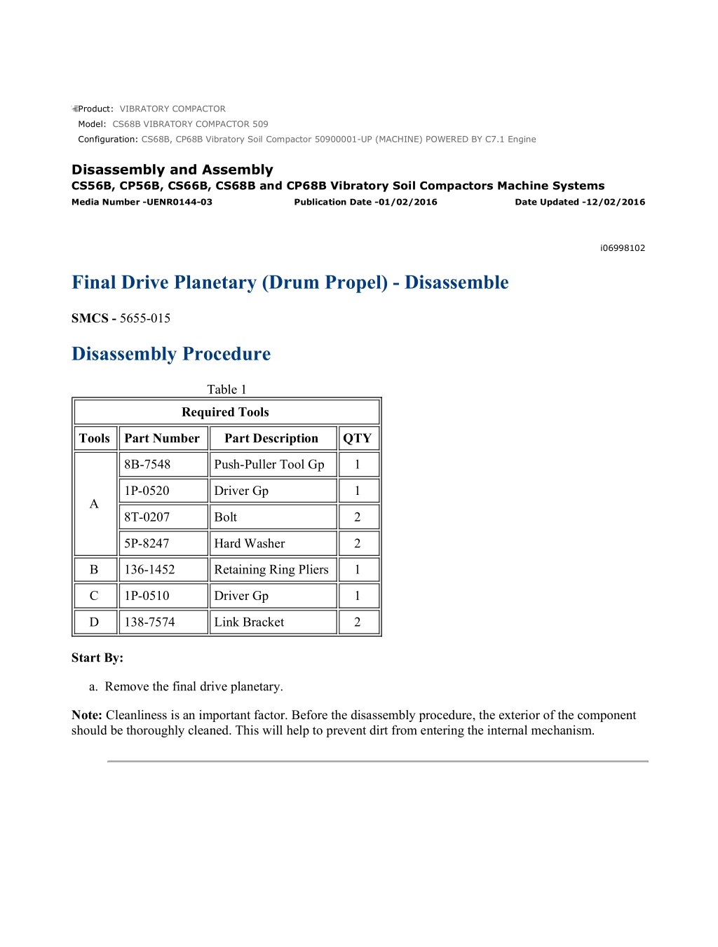
CS68B, CP68B Vibratory Soil Compactor 50900001-UP (MACHINE) POWERED B... 1/9 Product: VIBRATORY COMPACTOR Model: CS68B VIBRATORY COMPACTOR 509 Configuration: CS68B, CP68B Vibratory Soil Compactor 50900001-UP (MACHINE) POWERED BY C7.1 Engine Disassembly and Assembly CS56B, CP56B, CS66B, CS68B and CP68B Vibratory Soil Compactors Machine Systems Media Number -UENR0144-03 Publication Date -01/02/2016 Date Updated -12/02/2016 i06998102 Final Drive Planetary (Drum Propel) - Disassemble SMCS - 5655-015 Disassembly Procedure Table 1 Required Tools Tools Part Number Part Description QTY 8B-7548 Push-Puller Tool Gp 1 1P-0520 Driver Gp 1 A 8T-0207 Bolt 2 5P-8247 Hard Washer 2 B 136-1452 Retaining Ring Pliers 1 C 1P-0510 Driver Gp 1 D 138-7574 Link Bracket 2 Start By: a. Remove the final drive planetary. Note: Cleanliness is an important factor. Before the disassembly procedure, the exterior of the component should be thoroughly cleaned. This will help to prevent dirt from entering the internal mechanism. https://127.0.0.1/sisweb/sisweb/techdoc/techdoc_print_page.jsp?returnurl=/sisw... 2022/6/1
CS68B, CP68B Vibratory Soil Compactor 50900001-UP (MACHINE) POWERED B... 2/9 Illustration 1 g00977445 Illustration 2 g00831857 Sudden release of spring force can cause injury. To prevent the possibility of injury, follow the procedure to relieve the spring pressure. 1. Install Tooling (A) on the final drive planetary, as shown. Use Tooling (A) and compress springs (4) under retaining disc (2) enough to eliminate the spring pressure on retaining ring (1). 2. Use Tooling (B) and remove retaining ring (1). https://127.0.0.1/sisweb/sisweb/techdoc/techdoc_print_page.jsp?returnurl=/sisw... 2022/6/1
CS68B, CP68B Vibratory Soil Compactor 50900001-UP (MACHINE) POWERED B... 3/9 Illustration 3 g00831858 3. Remove retaining disc (2). 4. Remove springs (4) from brake piston (5). 5. Remove brake piston (5) from the hub. 6. Remove retaining ring (6), shims (8), and coupling (3) from sun gear (7). Illustration 4 g00977458 https://127.0.0.1/sisweb/sisweb/techdoc/techdoc_print_page.jsp?returnurl=/sisw... 2022/6/1
https://www.ebooklibonline.com Hello dear friend! Thank you very much for reading. Enter the link into your browser. The full manual is available for immediate download. https://www.ebooklibonline.com
CS68B, CP68B Vibratory Soil Compactor 50900001-UP (MACHINE) POWERED B... 4/9 7. Remove discs (11) and friction discs (10). 8. Remove O-ring seals (9) and (14). Remove backup rings (13) and (12). Note: When discs (11) and friction discs (10) are removed, some of the final drive planetaries will have shim (15) under the last disc. Illustration 5 g00977461 9. Remove retaining ring (16). Remove flange cover (17) from input ring gear (18). Illustration 6 g00977463 10. Remove bolts (19). Remove input ring gear (18) from the housing. Illustration 7 g00977464 https://127.0.0.1/sisweb/sisweb/techdoc/techdoc_print_page.jsp?returnurl=/sisw... 2022/6/1
CS68B, CP68B Vibratory Soil Compactor 50900001-UP (MACHINE) POWERED B... 5/9 11. Remove O-ring seals (20) and (21) from input ring gear (18). 12. Remove dowels (22) from input ring gear (18). Illustration 8 g00977466 Illustration 9 g00977467 13. Remove sun gear (7), planetary carrier (23), and sun gear (24) from the housing. 14. Remove sun gears (7) and (24) from planetary carrier (23). Illustration 10 g00831872 15. Remove retaining ring (26), antirotation washer (27), planetary gear (25), needle bearings (28), and the gear washer from gear pin (29). 16. Repeat Step 15 and remove the remaining two planetary gears. https://127.0.0.1/sisweb/sisweb/techdoc/techdoc_print_page.jsp?returnurl=/sisw... 2022/6/1
CS68B, CP68B Vibratory Soil Compactor 50900001-UP (MACHINE) POWERED B... 6/9 17. Remove gear pins (29) from planetary carrier (23), if necessary. 18. Remove disc (30) from planetary carrier (23), if necessary. Illustration 11 g00977595 19. Remove planetary carrier (31) from the housing. Illustration 12 g00831875 20. Remove retaining ring (35), gear washer (36), planetary gear (37), needle bearings (32), and the antirotation washer from gear pin (33). 21. Repeat Step 20 and remove the remaining two planetary gears. 22. Remove gear pins (33) from planetary carrier (31), if necessary. 23. Remove disc (34) from planetary carrier (31), if necessary. https://127.0.0.1/sisweb/sisweb/techdoc/techdoc_print_page.jsp?returnurl=/sisw... 2022/6/1
CS68B, CP68B Vibratory Soil Compactor 50900001-UP (MACHINE) POWERED B... 7/9 Illustration 13 g00831876 24. Remove sun gear (38) and bolts (39). Illustration 14 g06193037 Typical Example 25. Use Tooling (C) and a suitable puller to remove planetary carrier (40). Illustration 15 g00977635 26. Remove antirotation washers (41). Illustration 16 g00977598 27. Remove planetary gears (42) and needle bearings (43) from the planetary gear pins. There are needle bearings on each of the planetary gear pins. https://127.0.0.1/sisweb/sisweb/techdoc/techdoc_print_page.jsp?returnurl=/sisw... 2022/6/1
CS68B, CP68B Vibratory Soil Compactor 50900001-UP (MACHINE) POWERED B... 8/9 Illustration 17 g00978758 28. Remove planetary gear pins (44), antirotation washers (45), and retaining disc (46). Illustration 18 g00978761 29. Use Tooling (D) and a suitable lifting device to remove housing (47) from hub (48). The weight of the hub is 43 kg (95 lb). Illustration 19 g00978762 30. Remove bushings (49) from hub (47). 31. Remove the first half of Duo-Cone Seal (50). https://127.0.0.1/sisweb/sisweb/techdoc/techdoc_print_page.jsp?returnurl=/sisw... 2022/6/1
CS68B, CP68B Vibratory Soil Compactor 50900001-UP (MACHINE) POWERED B... 9/9 Illustration 20 g00978764 32. Remove the second half of Duo-Cone Seal (50) from housing (47). 33. Remove bearings (52), bearing cups (53) and retaining rings (51). https://127.0.0.1/sisweb/sisweb/techdoc/techdoc_print_page.jsp?returnurl=/sisw... 2022/6/1
CS68B, CP68B Vibratory Soil Compactor 50900001-UP (MACHINE) POWERED B... 1/10 Product: VIBRATORY COMPACTOR Model: CS68B VIBRATORY COMPACTOR 509 Configuration: CS68B, CP68B Vibratory Soil Compactor 50900001-UP (MACHINE) POWERED BY C7.1 Engine Disassembly and Assembly CS56B, CP56B, CS66B, CS68B and CP68B Vibratory Soil Compactors Machine Systems Media Number -UENR0144-03 Publication Date -01/02/2016 Date Updated -12/02/2016 i04782474 Final Drive Planetary (Drum Propel) - Disassemble SMCS - 5655-015 Disassembly Procedure Table 1 Required Tools Tools Part Number Part Description QTY 8B-7548 Push-Puller Tool Gp 1 1P-0520 Driver Gp 1 A 8T-0207 Bolt 2 5P-8247 Hard Washer 2 B 136-1452 Retaining Ring Pliers 1 1P-2320 Combination Puller 1 C 1P-0510 Driver Gp 1 D 138-7574 Link Bracket 2 Start By: a. Remove the final drive planetary. https://127.0.0.1/sisweb/sisweb/techdoc/techdoc_print_page.jsp?returnurl=/sisw... 2022/6/1
CS68B, CP68B Vibratory Soil Compactor 50900001-UP (MACHINE) POWERED B... 2/10 Illustration 1 g01415783 Sudden release of spring force can cause injury. To prevent the possibility of injury, follow the procedure to relieve the spring pressure. 1. Install Tooling (A) on the final drive planetary, as shown. Use Tooling (A) and compress springs (3) under retaining disc (2) enough to eliminate the spring pressure on retaining ring (1). 2. Use Tooling (B) and remove retaining ring (1). Illustration 2 g01415782 3. Remove retaining disc (2). https://127.0.0.1/sisweb/sisweb/techdoc/techdoc_print_page.jsp?returnurl=/sisw... 2022/6/1
CS68B, CP68B Vibratory Soil Compactor 50900001-UP (MACHINE) POWERED B... 3/10 Illustration 3 g01415998 4. Remove springs (3) from brake piston (4). Illustration 4 g01416182 5. Use two bolts in order to remove brake piston (4) from the hub. Illustration 5 g01416187 6. Remove O-ring seals (5). https://127.0.0.1/sisweb/sisweb/techdoc/techdoc_print_page.jsp?returnurl=/sisw... 2022/6/1
CS68B, CP68B Vibratory Soil Compactor 50900001-UP (MACHINE) POWERED B... 4/10 Illustration 6 g01416183 Illustration 7 g01416205 7. Remove bolt (7), washer (8), and coupling (6) from the hub, if equipped. Illustration 8 g01416193 8. Remove discs (11), friction discs (10), and shims (12). https://127.0.0.1/sisweb/sisweb/techdoc/techdoc_print_page.jsp?returnurl=/sisw... 2022/6/1
CS68B, CP68B Vibratory Soil Compactor 50900001-UP (MACHINE) POWERED B... 5/10 Note: When discs (11) and friction discs (10) are removed, some of the final drive planetaries will have shim (12) under the last disc. Illustration 9 g02167113 9. Remove the bolts and cover (13). Illustration 10 g02167114 10. Remove O-ring seal (14). Illustration 11 g02167115 https://127.0.0.1/sisweb/sisweb/techdoc/techdoc_print_page.jsp?returnurl=/sisw... 2022/6/1
CS68B, CP68B Vibratory Soil Compactor 50900001-UP (MACHINE) POWERED B... 6/10 11. Remove the bolts and cover (15). Illustration 12 g02167116 12. Remove O-ring seal (16) from cover (15). Illustration 13 g02167118 13. Remove sun gear assembly (17). 14. Remove planetary carrier (18). Illustration 14 g02167119 https://127.0.0.1/sisweb/sisweb/techdoc/techdoc_print_page.jsp?returnurl=/sisw... 2022/6/1
CS68B, CP68B Vibratory Soil Compactor 50900001-UP (MACHINE) POWERED B... 7/10 15. Use Tooling (B) and remove retaining ring (19). Remove antirotation washer (21), gear (22), and needle bearings (20). 16. Repeat Step 15 to disassemble the remaining two planetaries. Illustration 15 g02167120 17. Remove planetary carrier (23). Illustration 16 g02167121 18. Use Tooling (B) and remove retaining ring (24). Remove antirotation washer (26), gear (27), and needle bearings (25). 19. Repeat Step 18 to disassemble the remaining two planetaries. https://127.0.0.1/sisweb/sisweb/techdoc/techdoc_print_page.jsp?returnurl=/sisw... 2022/6/1
CS68B, CP68B Vibratory Soil Compactor 50900001-UP (MACHINE) POWERED B... 8/10 Illustration 17 g02890762 20. Remove sun gear (28) and bolts (29). Illustration 18 g02890337 21. Use Tooling (C) in order to remove planetary carrier (30). Illustration 19 g02890360 22. Remove antirotation washers (31). Illustration 20 g02890361 https://127.0.0.1/sisweb/sisweb/techdoc/techdoc_print_page.jsp?returnurl=/sisw... 2022/6/1
CS68B, CP68B Vibratory Soil Compactor 50900001-UP (MACHINE) POWERED B... 9/10 23. Remove planetary gears (32) and needle bearings (33) from the planetary gear pins. There are needle bearings on each of the planetary gear pins. Illustration 21 g02890376 24. Remove planetary gear pins (34), antirotation washers (35) and retaining disc (36). Illustration 22 g02890382 25. Use Tooling (D) and a suitable lifting device in order to remove housing (37) from hub (38). The weight of the hub (38) is 43 kg (95 lb). Illustration 23 g02890396 https://127.0.0.1/sisweb/sisweb/techdoc/techdoc_print_page.jsp?returnurl=/sisw... 2022/6/1
CS68B, CP68B Vibratory Soil Compactor 50900001-UP (MACHINE) POWERED ... 10/10 26. Remove bushings (39) from hub (38). 27. Remove the first half of Duo-Cone Seal (40). Illustration 24 g02890437 28. Remove the second half of Duo-Cone Seal (40) from housing (37). 29. Remove bearings (42), bearing cups (43) and retaining rings (41). https://127.0.0.1/sisweb/sisweb/techdoc/techdoc_print_page.jsp?returnurl=/sisw... 2022/6/1
CS68B, CP68B Vibratory Soil Compactor 50900001-UP (MACHINE) POWERED B... 1/10 Product: VIBRATORY COMPACTOR Model: CS68B VIBRATORY COMPACTOR 509 Configuration: CS68B, CP68B Vibratory Soil Compactor 50900001-UP (MACHINE) POWERED BY C7.1 Engine Disassembly and Assembly CS56B, CP56B, CS66B, CS68B and CP68B Vibratory Soil Compactors Machine Systems Media Number -UENR0144-03 Publication Date -01/02/2016 Date Updated -12/02/2016 i06781874 Final Drive Planetary (Drum Propel) - Assemble SMCS - 5655-016 Assembly Procedure Table 1 Required Tools Tools Part Number Part Description Qty 8B-7548 Push-Puller Tool Gp 1 1P-0520 Driver Gp 1 A 8T-0207 Bolt 2 5P-8247 Hard Washer 2 B 136-1452 Retaining Ring Pliers 1 D 138-7574 Link Bracket 2 E 220-5726 Duo-Cone Seal Installer As 1 F 5P-0960 Molybdenum Grease 1 G 9S-3263 Thread Lock Compound 1 Note: All of the components must be cleaned and inspected before assembly. If any of the components are beyond recommended limits, replace the components. Lubricate all moving parts with clean hydraulic oil during assembly. Assemble the final drive planetary with new seals. https://127.0.0.1/sisweb/sisweb/techdoc/techdoc_print_page.jsp?returnurl=/sisw... 2022/6/1
Suggest: For more complete manuals. Please go to the home page. https://www.ebooklibonline.com If the above button click is invalid. Please download this document first, and then click the above link to download the complete manual. Thank you so much for reading
CS68B, CP68B Vibratory Soil Compactor 50900001-UP (MACHINE) POWERED B... 2/10 Illustration 1 g02890856 1. Install retaining rings (41), bearing cups (43) and bearings (42) in housing (37). 2. Use Tooling (E) to install Duo-Cone Seal (40) in housing (37). Refer to Disassembly and Assembly, "Duo-Cone Conventional Seals - Install" for the correct procedure. Illustration 2 g02890876 3. Use Tooling (E) to install Duo-Cone Seal (40) in hub (38). Refer to Disassembly and Assembly, "Duo-Cone Conventional Seals - Install" for the correct procedure. 4. Install bushings (39) in hub (38). Illustration 3 g02890896 https://127.0.0.1/sisweb/sisweb/techdoc/techdoc_print_page.jsp?returnurl=/sisw... 2022/6/1
CS68B, CP68B Vibratory Soil Compactor 50900001-UP (MACHINE) POWERED B... 3/10 5. Use Tooling (D) and a suitable lifting device to install housing (37) on hub (38). The weight of the housing (37) is 43 kg (95 lb). Illustration 4 g02890956 Illustration 5 g02890916 Note: Planetary gear pins (34) are not symmetrical. Install the longer end of the planetary gear pins (34) in hub (38). Note: Planetary gear pins (34) and the bores in hub (38) must be clean to allow proper installation. 6. Apply Tooling (F) on the shoulders of planetary gear pins (34). Install antirotation washers (35) on planetary gear pins (34). 7. Install antirotation washers (35) and planetary gear pins (34) in hub (38). 8. Install retaining disc (36). https://127.0.0.1/sisweb/sisweb/techdoc/techdoc_print_page.jsp?returnurl=/sisw... 2022/6/1
https://www.ebooklibonline.com Hello dear friend! Thank you very much for reading. Enter the link into your browser. The full manual is available for immediate download. https://www.ebooklibonline.com
")
")
")

")
")
")
")
")
")
")
")
")
")
")
")
")
")
")
")
")

")
")