Caterpillar Cat 962G II WHEEL LOADER (Prefix BAC) Service Repair Manual Instant Download (BAC00001 and up)
Please open the website below to get the complete manualnn//

Download Presentation

Please find below an Image/Link to download the presentation.
The content on the website is provided AS IS for your information and personal use only. It may not be sold, licensed, or shared on other websites without obtaining consent from the author. Download presentation by click this link. If you encounter any issues during the download, it is possible that the publisher has removed the file from their server.
E N D
Presentation Transcript
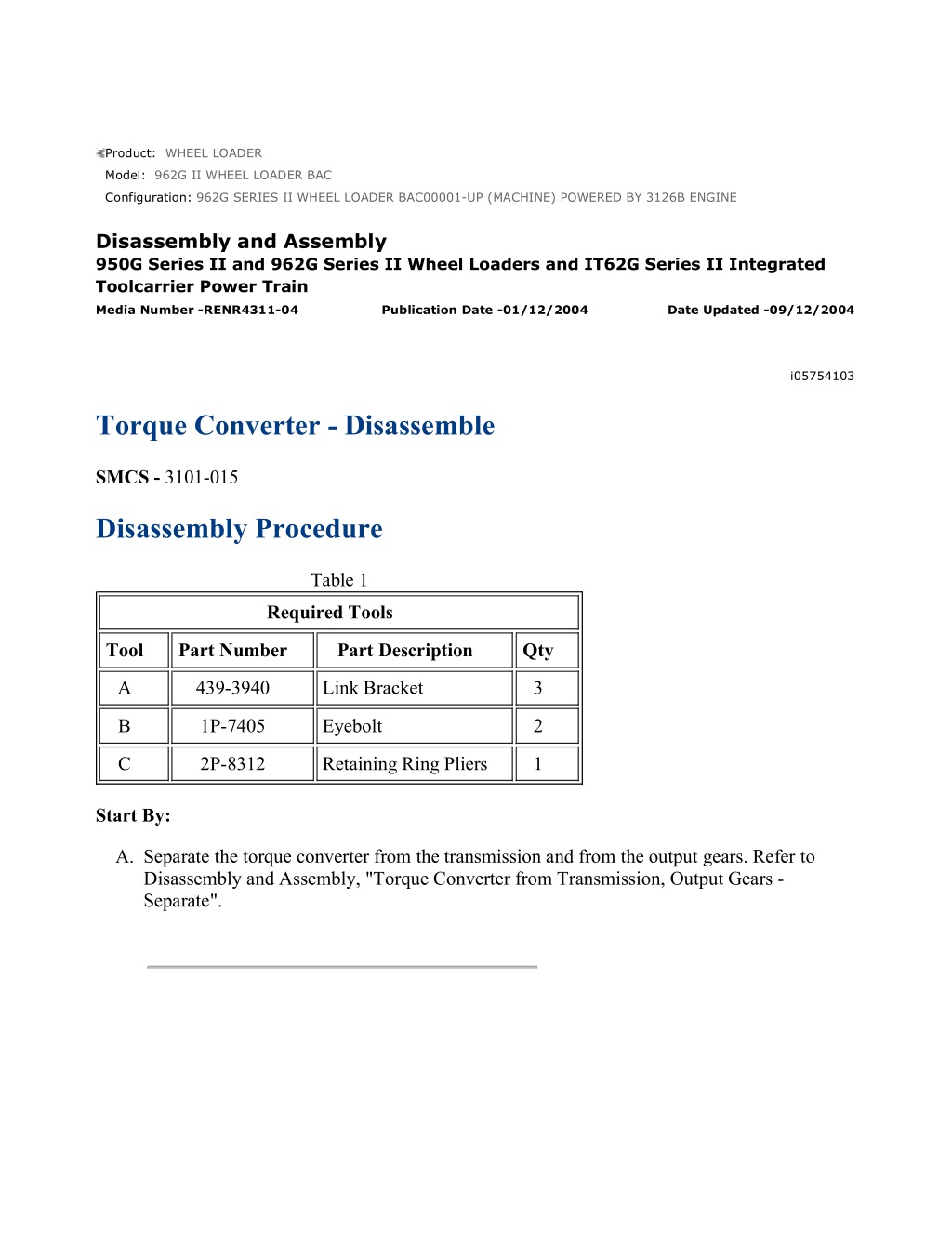
962G SERIES II WHEEL LOADER BAC00001-UP (MACHINE) POWERED BY 31... 1/13 Product: WHEEL LOADER Model: 962G II WHEEL LOADER BAC Configuration: 962G SERIES II WHEEL LOADER BAC00001-UP (MACHINE) POWERED BY 3126B ENGINE Disassembly and Assembly 950G Series II and 962G Series II Wheel Loaders and IT62G Series II Integrated Toolcarrier Power Train Media Number -RENR4311-04 Publication Date -01/12/2004 Date Updated -09/12/2004 i05754103 Torque Converter - Disassemble SMCS - 3101-015 Disassembly Procedure Table 1 Required Tools Tool Part Number Part Description Qty A 439-3940 Link Bracket 3 B 1P-7405 Eyebolt 2 C 2P-8312 Retaining Ring Pliers 1 Start By: A. Separate the torque converter from the transmission and from the output gears. Refer to Disassembly and Assembly, "Torque Converter from Transmission, Output Gears - Separate". https://127.0.0.1/sisweb/sisweb/techdoc/techdoc_print_page.jsp?returnurl=/sis... 2022/3/12
962G SERIES II WHEEL LOADER BAC00001-UP (MACHINE) POWERED BY 31... 2/13 Illustration 1 g00319444 1. Use Tooling (A) and a suitable lifting device to place torque converter housing (1) onto suitable cribbing, as shown. Illustration 2 g00319445 2. Remove transmission oil pump (2) . Refer to Disassembly and Assembly, "Transmission Oil Pump - Remove". 3. Remove bolt (3) and washer (4) . https://127.0.0.1/sisweb/sisweb/techdoc/techdoc_print_page.jsp?returnurl=/sis... 2022/3/12
962G SERIES II WHEEL LOADER BAC00001-UP (MACHINE) POWERED BY 31... 3/13 Illustration 3 g00319447 4. Remove torque converter speed sensor (5) . Illustration 4 g00319448 5. Remove bolts (6) that hold the torque converter to the torque converter housing. Illustration 5 g00319449 6. Remove bolts (7) and pump drive flange (8) . https://127.0.0.1/sisweb/sisweb/techdoc/techdoc_print_page.jsp?returnurl=/sis... 2022/3/12
https://www.ebooklibonline.com Hello dear friend! Thank you very much for reading. Enter the link into your browser. The full manual is available for immediate download. https://www.ebooklibonline.com
962G SERIES II WHEEL LOADER BAC00001-UP (MACHINE) POWERED BY 31... 4/13 Illustration 6 g00319450 7. Remove bolt (9) that holds shaft (10) to the torque converter housing. Illustration 7 g00319451 8. Install Tooling (B) in pump drive gear (11) . 9. Lift pump drive gear (11) and drive gear shaft (10) . Lift drive gear shaft (10) out of the torque converter housing bore. 10. Place the assembly to one side of the torque converter housing bore. Make sure that drive gear shaft (10) is not in the torque converter housing bore. https://127.0.0.1/sisweb/sisweb/techdoc/techdoc_print_page.jsp?returnurl=/sis... 2022/3/12
962G SERIES II WHEEL LOADER BAC00001-UP (MACHINE) POWERED BY 31... 5/13 Illustration 8 g00319453 11. Remove Tooling (B) from pump drive gear (11) . 12. Remove drive gear shaft (10) from pump drive gear (11) . 13. Remove bearing (12) from pump drive gear (11) . Illustration 9 g03652939 14. Use Tooling (A) and a suitable lifting device to remove torque converter housing (1) . The weight of torque converter housing (1) is approximately 113 kg (250 lb). https://127.0.0.1/sisweb/sisweb/techdoc/techdoc_print_page.jsp?returnurl=/sis... 2022/3/12
962G SERIES II WHEEL LOADER BAC00001-UP (MACHINE) POWERED BY 31... 6/13 Illustration 10 g03652860 15. Turn torque converter housing (1) over to remove pump drive gear (11) . Illustration 11 g00319455 16. Remove drive gear (13) . Illustration 12 g00319456 17. Remove retaining ring (14) that holds output shaft (15) . https://127.0.0.1/sisweb/sisweb/techdoc/techdoc_print_page.jsp?returnurl=/sis... 2022/3/12
962G SERIES II WHEEL LOADER BAC00001-UP (MACHINE) POWERED BY 31... 7/13 18. Use a soft faced hammer in order to free the bearing from the carrier assembly. Remove output shaft (15) from the carrier assembly. Illustration 13 g00319500 19. Remove seal ring (16) from output shaft (15) . 20. Use a suitable press to remove roller bearing (17) . Illustration 14 g00319458 21. Remove bolts (18) . Remove torque converter impeller (19) from the impeller housing. Note: If the torque converter is equipped with a freewheel stator, continue with Steps 22 through 28. https://127.0.0.1/sisweb/sisweb/techdoc/techdoc_print_page.jsp?returnurl=/sis... 2022/3/12
962G SERIES II WHEEL LOADER BAC00001-UP (MACHINE) POWERED BY 31... 8/13 Illustration 15 g00877132 22. Turn impeller (20) to the opposite side. 23. Remove retaining ring (21) and spacer (22) from carrier shaft (23) . 24. Remove stator (24) . Illustration 16 g00877125 25. Remove retaining ring (25) and washer (26) from stator (24) . Repeat the procedure for the opposite side of stator (24) . https://127.0.0.1/sisweb/sisweb/techdoc/techdoc_print_page.jsp?returnurl=/sis... 2022/3/12
962G SERIES II WHEEL LOADER BAC00001-UP (MACHINE) POWERED BY 31... 9/13 Illustration 17 g00877126 Note: If necessary, Raise the temperature of the stator to a maximum temperature of 135 C (275 F) for approximately 15 minutes. 26. Remove bearing race (27) , freewheel rollers (28) , freewheel springs (29) , and freewheel cam (30) from stator (24) . Illustration 18 g00877129 27. Remove spacer (31) from impeller (20) . https://127.0.0.1/sisweb/sisweb/techdoc/techdoc_print_page.jsp?returnurl=/sis... 2022/3/12
962G SERIES II WHEEL LOADER BAC00001-UP (MACHINE) POWERED BY ... 10/13 Illustration 19 g00877133 28. Use a press to remove carrier shaft (23) from impeller (20) . Illustration 20 g00877250 29. Remove bolts (32) and drive gear (33) from the torque converter impeller. Illustration 21 g00877257 30. Remove roller bearing (34) from torque converter impeller (19) . https://127.0.0.1/sisweb/sisweb/techdoc/techdoc_print_page.jsp?returnurl=/sis... 2022/3/12
962G SERIES II WHEEL LOADER BAC00001-UP (MACHINE) POWERED BY ... 11/13 Illustration 22 g00877258 31. Remove seal ring (36) from carrier assembly (35) . 32. If necessary, remove locating dowel (37) . Illustration 23 g01146281 33. Remove ring (39A) . Remove retaining ring (38) and impeller cover (39) from impeller housing (40) . https://127.0.0.1/sisweb/sisweb/techdoc/techdoc_print_page.jsp?returnurl=/sis... 2022/3/12
962G SERIES II WHEEL LOADER BAC00001-UP (MACHINE) POWERED BY ... 12/13 Illustration 24 g00877261 34. Use Tooling (C) in order to remove retaining ring (41) . Illustration 25 g00877262 35. Remove bearing spacer (42) . 36. Remove O-ring seal (43) . Illustration 26 g00877263 37. Turn the impeller housing onto the opposite side. Remove turbine assembly (44) . https://127.0.0.1/sisweb/sisweb/techdoc/techdoc_print_page.jsp?returnurl=/sis... 2022/3/12
962G SERIES II WHEEL LOADER BAC00001-UP (MACHINE) POWERED BY ... 13/13 Illustration 27 g00877264 38. Remove bolts (45) . Separate turbine (46) from turbine hub assembly (47) . 39. If necessary, remove locating dowel (48) . Illustration 28 g00877265 40. Remove roller bearing (49) from the impeller housing. https://127.0.0.1/sisweb/sisweb/techdoc/techdoc_print_page.jsp?returnurl=/sis... 2022/3/12
962G SERIES II WHEEL LOADER BAC00001-UP (MACHINE) POWERED BY 31... 1/12 Product: WHEEL LOADER Model: 962G II WHEEL LOADER BAC Configuration: 962G SERIES II WHEEL LOADER BAC00001-UP (MACHINE) POWERED BY 3126B ENGINE Disassembly and Assembly 950G Series II and 962G Series II Wheel Loaders and IT62G Series II Integrated Toolcarrier Power Train Media Number -RENR4311-04 Publication Date -01/12/2004 Date Updated -09/12/2004 i05754104 Torque Converter - Assemble SMCS - 3101-016 Assembly Procedure Table 1 Required Tools Tool Part Number Part Description Qty A 439-3940 Link Bracket 3 B 1P-7405 Eyebolt 2 C 2P-8312 Pliers 1 D - Loctite 536 - Illustration 1 g00877265 https://127.0.0.1/sisweb/sisweb/techdoc/techdoc_print_page.jsp?returnurl=/sis... 2022/3/12
962G SERIES II WHEEL LOADER BAC00001-UP (MACHINE) POWERED BY 31... 2/12 Note: The notch on roller bearing (49) must be aligned with locating dowel (48) . 1. Install roller bearing (49) . Illustration 2 g00877264 2. Install locating dowel (48) in turbine hub assembly (38) . 3. Install turbine hub assembly (47) to turbine (46) . Install bolts (45) . The torque for bolts (45) is 60 7 N m (44 5 lb ft). Illustration 3 g00877263 4. Install the impeller housing over turbine assembly (44) , as shown. https://127.0.0.1/sisweb/sisweb/techdoc/techdoc_print_page.jsp?returnurl=/sis... 2022/3/12
962G SERIES II WHEEL LOADER BAC00001-UP (MACHINE) POWERED BY 31... 3/12 Illustration 4 g00877262 5. Install O-ring seal (43) . 6. Install bearing spacer (42) . Illustration 5 g00877261 7. Use Tooling (C) in order to install retaining ring (41) . Illustration 6 g01146281 https://127.0.0.1/sisweb/sisweb/techdoc/techdoc_print_page.jsp?returnurl=/sis... 2022/3/12
962G SERIES II WHEEL LOADER BAC00001-UP (MACHINE) POWERED BY 31... 4/12 8. Install impeller cover (39) and retaining ring (38) in impeller housing (40) . Install ring (39A) . Illustration 7 g00877258 9. Install locating dowel (37) . 10. Install seal ring (36) on carrier assembly (35) . Illustration 8 g00877257 Note: The notch in roller bearing (34) must be facing upward. 11. Install roller bearing (34) in torque converter impeller (19) . https://127.0.0.1/sisweb/sisweb/techdoc/techdoc_print_page.jsp?returnurl=/sis... 2022/3/12
962G SERIES II WHEEL LOADER BAC00001-UP (MACHINE) POWERED BY 31... 5/12 Illustration 9 g00877250 12. Install drive gear (33) and bolts (32) on the torque converter impeller. The torque for bolts (32) is 105 15 N m (75 11 lb ft). Note: If the torque converter is equipped with a freewheel stator, continue with Steps 13 through 18. Illustration 10 g00877133 13. Use a suitable press to install carrier shaft (23) in impeller (20) . https://127.0.0.1/sisweb/sisweb/techdoc/techdoc_print_page.jsp?returnurl=/sis... 2022/3/12
962G SERIES II WHEEL LOADER BAC00001-UP (MACHINE) POWERED BY 31... 6/12 Illustration 11 g00877129 14. Install spacer (31) on impeller (20) . Illustration 12 g00877126 Note: If necessary, Raise the temperature of stator (24) to a maximum temperature of 135 C (275 F). Install the cam with the IMPELLER SIDE facing downward. Continue with the installation until freewheel cam (30) contacts the retaining ring (not shown). 15. Install freewheel cam (30) , freewheel springs (29) , freewheel rollers (28) , and bearing race (27) in stator (24) . Note: Install freewheel springs (29) with the maximum number of loops toward the outside diameter of freewheel cam (30) . Illustration 13 g00877125 16. Install washer (26) and snap ring (25) on stator (24) . Repeat the procedure for the opposite side of stator (24) . https://127.0.0.1/sisweb/sisweb/techdoc/techdoc_print_page.jsp?returnurl=/sis... 2022/3/12
962G SERIES II WHEEL LOADER BAC00001-UP (MACHINE) POWERED BY 31... 7/12 Illustration 14 g00877132 17. Install stator (24) on impeller (20) . 18. Install spacer (22) and snap ring (21) on carrier shaft (23) . Illustration 15 g00319458 19. Install torque converter impeller (19) on the impeller housing. 20. Install bolts (18) . The torque for bolts (18) is 60 7 N m (44 5 lb ft). https://127.0.0.1/sisweb/sisweb/techdoc/techdoc_print_page.jsp?returnurl=/sis... 2022/3/12
Suggest: For more complete manuals. Please go to the home page. https://www.ebooklibonline.com If the above button click is invalid. Please download this document first, and then click the above link to download the complete manual. Thank you so much for reading
962G SERIES II WHEEL LOADER BAC00001-UP (MACHINE) POWERED BY 31... 8/12 Illustration 16 g00319500 21. Install roller bearing (17) on output shaft (15) . 22. Install seal ring (16) . Illustration 17 g00319456 23. Install output shaft (15) in the carrier assembly. 24. Install retaining ring (14) that secures output shaft (15) . Illustration 18 g00319455 25. Install drive gear (13) . https://127.0.0.1/sisweb/sisweb/techdoc/techdoc_print_page.jsp?returnurl=/sis... 2022/3/12
962G SERIES II WHEEL LOADER BAC00001-UP (MACHINE) POWERED BY 31... 9/12 Illustration 19 g03652860 26. Install pump drive gear (11) to the underside of torque converter housing (1) . Illustration 20 g03652939 27. Install Tooling (A) and a suitable lifting device to install torque converter housing (1) onto the torque converter assembly. The weight of torque converter housing (1) is approximately 113 kg (250 lb). Illustration 21 g00319448 https://127.0.0.1/sisweb/sisweb/techdoc/techdoc_print_page.jsp?returnurl=/sis... 2022/3/12
https://www.ebooklibonline.com Hello dear friend! Thank you very much for reading. Enter the link into your browser. The full manual is available for immediate download. https://www.ebooklibonline.com
 POWERED BY")
 POWERED BY")
 POWERED BY")

 POWERED BY")
 POWERED BY")
 POWERED BY")
 POWERED BY")
 POWERED BY")
 POWERED BY")
 POWERED BY")
 POWERED BY")
 POWERED BY")
 POWERED BY")
 POWERED BY")
 POWERED BY")
 POWERED BY")
 POWERED BY")
 POWERED BY")
 POWERED BY")
 POWERED BY")

 POWERED BY")
 POWERED BY")