Caterpillar Cat 3512C Industrial Engine (Prefix SRF) Service Repair Manual Instant Download (SRF00001 and up)
Please open the website below to get the complete manualnn//

Download Presentation

Please find below an Image/Link to download the presentation.
The content on the website is provided AS IS for your information and personal use only. It may not be sold, licensed, or shared on other websites without obtaining consent from the author. Download presentation by click this link. If you encounter any issues during the download, it is possible that the publisher has removed the file from their server.
E N D
Presentation Transcript
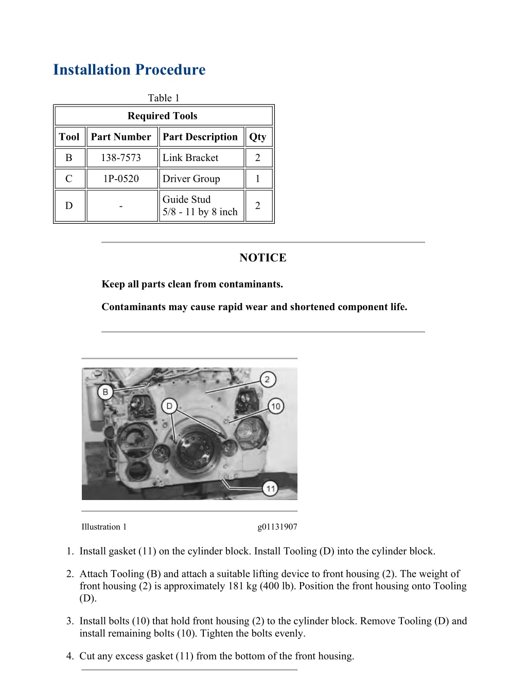
Installation Procedure Table 1 Required Tools Tool Part Number Part Description Qty B 138-7573 Link Bracket 2 C 1P-0520 Driver Group 1 Guide Stud 5/8 - 11 by 8 inch D - 2 NOTICE Keep all parts clean from contaminants. Contaminants may cause rapid wear and shortened component life. Illustration 1 g01131907 1. Install gasket (11) on the cylinder block. Install Tooling (D) into the cylinder block. 2. Attach Tooling (B) and attach a suitable lifting device to front housing (2). The weight of front housing (2) is approximately 181 kg (400 lb). Position the front housing onto Tooling (D). 3. Install bolts (10) that hold front housing (2) to the cylinder block. Remove Tooling (D) and install remaining bolts (10). Tighten the bolts evenly. 4. Cut any excess gasket (11) from the bottom of the front housing. https://127.0.0.1/sisweb/sisweb/techdoc/techdoc_print_page.jsp?returnurl=/sisweb/sisw... 2022/4/27
w 5/6(W) Illustration 2 g01131955 5. Use Tooling (C) to install sleeve bearing (6) in idler gear (5). 6. Install O-ring seal (8) on shaft (4). Apply clean engine oil to the bore in front housing (2) for the shaft. 7. Position thrust washer (9), idler gear (5), and shaft (4) in the front housing. Install bolts (7). Illustration 3 g01246380 8. Install the O-ring seal in cover (3). Position cover (3) on front housing (2) and install the bolts. 9. Position the gaskets and covers (1) on front housing (2) and install the bolts. End By: a. If necessary, install the engine oil pump and water pump drive. Refer to Disassembly and Assembly, "Accessory Drive (Front) - Install". https://127.0.0.1/sisweb/sisweb/techdoc/techdoc_print_page.jsp?returnurl=/sisweb/sisw... 2022/4/27
w 6/6(W) b. If necessary, install the accessory drive. Refer to Disassembly and Assembly, "Accessory Drive (Front) - Install". c. Install the crankshaft front seal and the wear sleeve. Refer to Disassembly and Assembly, "Crankshaft Front Seal and Wear Sleeve - Install". d. Install the engine oil filter housing. Refer to Disassembly and Assembly, "Engine Oil Filter Housing - Install". https://127.0.0.1/sisweb/sisweb/techdoc/techdoc_print_page.jsp?returnurl=/sisweb/sisw... 2022/4/27
https://www.ebooklibonline.com Hello dear friend! Thank you very much for reading. Enter the link into your browser. The full manual is available for immediate download. https://www.ebooklibonline.com
w 4/5(W) Removal Procedure Table 1 Required Tools Tool Part Number Part Description Qty A 138-7573 Lifting Bracket 2 Guide Stud 1 - 14 by 10 inch B - 2 Illustration 1 g01137704 1. Remove two bolts (1) and install Tooling (B). 2. Remove two bolts (3) and attach Tooling (A) and a suitable lifting device to vibration damper (2). The weight of vibration damper (2) is approximately 175 kg (385 lb). Remove remaining bolts (1). Remove vibration damper (2). Installation Procedure Table 2 Required Tools Tool Part Number Part Description Qty A 138-7573 Lifting Bracket 2 B - 2 https://127.0.0.1/sisweb/sisweb/techdoc/techdoc_print_page.jsp?returnurl=/sisweb/sisw... 2022/4/27
w 5/5(W) Guide Stud 1 - 14 by 10 inch C Loctite 243 - Illustration 2 g01137704 1. Install Tooling (B) in the crankshaft. 2. Attach Tooling (A) and a suitable lifting device to vibration damper (2). The weight of vibration damper (2) is approximately 175 kg (385 lb). 3. Install the vibration damper on Tooling (B). Install bolts (1). Remove Tooling (B) and install remaining bolts (1). Tighten bolts (1) to a torque of 1125 100 N m (820 74 lb ft). 4. Remove Tooling (A). Apply Tooling (C) to the threads of bolts (3). Install bolts (3) and tighten to a torque of 55 7 N m (41 5 lb ft). https://127.0.0.1/sisweb/sisweb/techdoc/techdoc_print_page.jsp?returnurl=/sisweb/sisw... 2022/4/27
w 4/5(W) Removal Procedure Table 1 Required Tools Tool Part Number Part Description Qty A 1U-7600 Slide Hammer Puller 1 1U-7325 Distorter Adapter - B 6V-3143 Distorter Adapter(1) - C 5P-7409 Sleeve Distorter 1 (1)For use with engines equipped with a seal adapter. Start By: a. Remove the vibration damper. Refer to Disassembly and Assembly, "Vibration Damper - Remove and Install". NOTICE Keep all parts clean from contaminants. Contaminants may cause rapid wear and shortened component life. NOTICE Every time that the crankshaft seal is removed from the wear sleeve, a new wear sleeve and crankshaft seal must be installed. https://127.0.0.1/sisweb/sisweb/techdoc/techdoc_print_page.jsp?returnurl=/sisweb/sisw... 2022/4/27
w 5/5(W) Illustration 1 g00659180 1. Drill three evenly spaced holes in crankshaft front seal (1) and use Tooling (A) to remove crankshaft front seal (1) from the front housing. Illustration 2 g00659181 2. Insert Tooling (B) between the front housing and wear sleeve (2). NOTICE The use of excessive force on the sleeve distorter can cause the distorter adapter to crack the housing. To help avoid damage to the engine, do not use excessive force to remove the wear sleeve. 3. Insert Tooling (C) between Tooling (B) and wear sleeve (2). Carefully turn Tooling (C) until the edge of the tool creates a crease in wear sleeve (2). Repeat this procedure several times around wear sleeve (2) until wear sleeve (2) can be removed by hand. https://127.0.0.1/sisweb/sisweb/techdoc/techdoc_print_page.jsp?returnurl=/sisweb/sisw... 2022/4/27
w 4/6(W) Installation Procedure For Seals 113-8432 and 113-8433 Table 1 Required Tools Tool Part Number Part Description Qty 6V-4003(1) Seal Locator As 1 D 2N-5006(1) Bolt 2 E 8T-3099(1) Seal Installer 1 F 9S-8858(1) Nut 1 G - (Loctite 620) - H 484-7863 (2) Tool As 1 (1)For installation of seals 113-8432 and 113-8433 (2)For Installation of seals 436-1478 and 436-1479 NOTICE Keep all parts clean from contaminants. Contaminants may cause rapid wear and shortened component life. Note: The crankshaft front seal and the wear sleeve must be replaced at the same time. Once the crankshaft front seal and the wear sleeve are separated, these components cannot be used again. Note: Do not use any type of lubricant during the installation of the crankshaft front seal and the wear sleeve. 1. Before installation of the crankshaft front seal and the wear sleeve, inspect the crankshaft for scratches. Also, inspect the crankshaft for any distortion on the surface that may lead to an out of round condition. Use a polishing cloth to remove any imperfections on the crankshaft. https://127.0.0.1/sisweb/sisweb/techdoc/techdoc_print_page.jsp?returnurl=/sisweb/sisw... 2022/4/27
Suggest: For more complete manuals. Please go to the home page. https://www.ebooklibonline.com If the above button click is invalid. Please download this document first, and then click the above link to download the complete manual. Thank you so much for reading
w 5/6(W) Illustration 1 g01136390 2. Clean the outside diameter of crankshaft (3) and the inside diameter of the new wear sleeve (2). Clean the bore for the crankshaft front seal in front housing (4).Apply Tooling (G) to the inner diameter of the wear sleeve and the surface of the crankshaft prior to assembly. 3. Install Tooling (D) on crankshaft (3). 4. Place crankshaft front seal (1) and wear sleeve (2) onto Tooling (D). 5. Position Tooling (E) onto Tooling (D). Lubricate the face of the washer on Tooling (F). Install Tooling (F) onto Tooling (E). Tighten Tooling (F) until Tooling (E) contacts Tooling (D). 6. Remove the Tooling from the crankshaft. 7. Check the crankshaft front seal and the wear sleeve for the correct installation. Installation Procedure For Seals 436-1478 and 436-1479 NOTICE Keep all parts clean from contaminants. Contaminants may cause rapid wear and shortened component life. NOTICE https://127.0.0.1/sisweb/sisweb/techdoc/techdoc_print_page.jsp?returnurl=/sisweb/sisw... 2022/4/27
w 6/6(W) Do not place engine oil on the crankshaft seal for installation. Lubrication of the crankshaft seal can give a false indication of leakage at a later time. Note: Ensure that there are no imperfections on the mating surfaces of the crankshaft, the installation tooling, or on the sealing surface of the crankshaft. Surface imperfections can distort the seal during installation and will cause the seal to malfunction. Illustration 2 g06042396 1. Using Tooling (H), install front seal (1) as outlined in the following steps: a. Install pilot (H1) to the crankshaft and install bolts (H2). b. Position front seal (1) onto pilot (H1). c. Install driver (H3) onto the shaft of pilot (H1). Mark driver (H3) at the 12 O' Clock position. Install bearing (H4) and nut (H5). d. Tighten nut (H5) until the base of driver (H3) contacts the skirt of pilot (H1). Loosen nut (H5) and rotate driver (H3) 180 degree. Retighten nut (H5) until driver (H3) contacts the skirt of pilot (H1). 2. Remove Tooling (H). End By: a. Install the vibration damper. https://127.0.0.1/sisweb/sisweb/techdoc/techdoc_print_page.jsp?returnurl=/sisweb/sisw... 2022/4/27
https://www.ebooklibonline.com Hello dear friend! Thank you very much for reading. Enter the link into your browser. The full manual is available for immediate download. https://www.ebooklibonline.com