CASE IH Magnum 200 Powershift Transmission (PST) TIER 4B Tractor Service Repair Manual Instant Download (PIN ZERH08100 and above)
Please open the website below to get the complete manualnn// n

Download Presentation

Please find below an Image/Link to download the presentation.
The content on the website is provided AS IS for your information and personal use only. It may not be sold, licensed, or shared on other websites without obtaining consent from the author. Download presentation by click this link. If you encounter any issues during the download, it is possible that the publisher has removed the file from their server.
E N D
Presentation Transcript
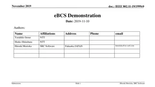
Magnum 180 Magnum 200 Magnum 220 Powershift Transmission (PST) Tractor PIN ZERH08100 and above SERVICE MANUAL Printed in U.S.A. Part number 47748093 1st edition English September 2014 Copyright 2014 CNH Industrial America LLC. All Rights Reserved. Case IH is a registered trademark of CNH Industrial America LLC. Racine Wisconsin 53404 U.S.A.
SERVICE MANUAL Magnum 180 696110052 PST TIER 4B [ZERH08100 - ] Magnum 200 696110062 PST TIER 4B [ZERH08100 - ] Magnum 220 696110072 PST TIER 4B [ZERH08100 - ] 47748093 26/09/2014 EN
Link Product / Engine Product Market Product North America Engine Magnum 180 696110052 PST TIER 4B [ZERH08100 - ] Magnum 180 696110052 PST TIER 4B [ZERH08100 - ] Magnum 200 696110062 PST TIER 4B [ZERH08100 - ] Magnum 200 696110062 PST TIER 4B [ZERH08100 - ] Magnum 220 696110072 PST TIER 4B [ZERH08100 - ] Magnum 220 696110072 PST TIER 4B [ZERH08100 - ] F4HFE613K*B002 Australia New Zealand F4HFE613K*B002 Australia New Zealand F4HFE613J*B005 North America F4HFE613J*B005 North America F4HFE613H*B003 Australia New Zealand F4HFE613H*B003 47748093 26/09/2014
https://www.ebooklibonline.com Hello dear friend! Thank you very much for reading. Enter the link into your browser. The full manual is available for immediate download. https://www.ebooklibonline.com
Contents INTRODUCTION Engine....................................................................................... 10 [10.001] Engine and crankcase ............................................................. 10.1 [10.216] Fuel tanks .......................................................................... 10.2 [10.218] Fuel injection system............................................................... 10.3 [10.202] Air cleaners and lines .............................................................. 10.4 [10.500] Selective Catalytic Reduction (SCR) exhaust treatment........................... 10.5 [10.400] Engine cooling system ............................................................. 10.6 [10.414] Fan and drive ...................................................................... 10.7 [10.310] Aftercooler.......................................................................... 10.8 [10.304] Engine lubrication system.......................................................... 10.9 Power coupling........................................................................... 19 [19.100] Drive shaft.......................................................................... 19.1 [19.110] Flywheel damper ................................................................... 19.2 Transmission.............................................................................. 21 [21.113] Powershift transmission ............................................................ 21.1 [21.135] Powershift transmission external controls.......................................... 21.2 [21.155] Powershift transmission internal components...................................... 21.3 [21.160] Creeper ............................................................................ 21.4 [21.166] Overdrive........................................................................... 21.5 [21.200] Dropbox ............................................................................ 21.6 Four-Wheel Drive (4WD) system .................................................. 23 [23.202] Electro-hydraulic control ........................................................... 23.1 [23.314] Drive shaft.......................................................................... 23.2 Front axle system ....................................................................... 25 [25.100] Powered front axle ................................................................. 25.1 47748093 26/09/2014
[25.102] Front bevel gear set and differential ............................................... 25.2 [25.108] Final drive hub, steering knuckles, and shafts ..................................... 25.3 [25.122] Axle suspension control............................................................ 25.4 Rear axle system........................................................................ 27 [27.100] Powered rear axle.................................................................. 27.1 [27.106] Rear bevel gear set and differential................................................ 27.2 Power Take-Off (PTO)................................................................. 31 [31.104] Rear electro-hydraulic control...................................................... 31.1 [31.114] Two-speed rear Power Take-Off (PTO) ............................................ 31.2 Brakes and controls .................................................................... 33 [33.202] Hydraulic service brakes ........................................................... 33.1 [33.110] Parking brake or parking lock ...................................................... 33.2 [33.220] Trailer brake hydraulic control...................................................... 33.3 Hydraulic systems....................................................................... 35 [35.000] Hydraulic systems.................................................................. 35.1 [35.102] Pump control valves................................................................ 35.2 [35.104] Fixed displacement pump.......................................................... 35.3 [35.105] Charge pump....................................................................... 35.4 [35.106] Variable displacement pump ....................................................... 35.5 [35.114] Three-point hitch control valve ..................................................... 35.6 [35.116] Three-point hitch cylinder .......................................................... 35.7 [35.204] Remote control valves ............................................................. 35.8 [35.300] Reservoir, cooler, and filters........................................................ 35.9 Hitches, drawbars, and implement couplings.................................. 37 [37.110] Rear three-point hitch .............................................................. 37.1 Frames and ballasting................................................................. 39 [39.140] Ballasts and supports .............................................................. 39.1 Steering..................................................................................... 41 47748093 26/09/2014
[41.101] Steering control .................................................................... 41.1 [41.200] Hydraulic control components...................................................... 41.2 [41.206] Pump............................................................................... 41.3 Wheels...................................................................................... 44 [44.520] Rear wheels........................................................................ 44.1 Cab climate control..................................................................... 50 [50.100] Heating............................................................................. 50.1 [50.200] Air conditioning..................................................................... 50.2 [50.300] Cab pressurizing system........................................................... 50.3 Electrical systems....................................................................... 55 [55.010] Fuel injection system............................................................... 55.1 [55.011] Fuel tank system ................................................................... 55.2 [55.014] Engine intake and exhaust system................................................. 55.3 [55.024] Transmission control system....................................................... 55.4 [55.031] Parking brake electrical system.................................................... 55.5 [55.045] Front axle control system .......................................................... 55.6 [55.046] Rear axle control system........................................................... 55.7 [55.047] Steering control system ............................................................ 55.8 [55.050] Heating, Ventilation, and Air-Conditioning (HVAC) control system................. 55.9 [55.051] Cab Heating, Ventilation, and Air-Conditioning (HVAC) controls................. 55.10 [55.100] Harnesses and connectors....................................................... 55.11 [55.130] Rear three-point hitch electronic control system ................................. 55.12 [55.201] Engine starting system........................................................... 55.13 [55.301] Alternator......................................................................... 55.14 [55.302] Battery............................................................................ 55.15 [55.408] Warning indicators, alarms, and instruments .................................... 55.16 [55.512] Cab controls...................................................................... 55.17 [55.518] Wiper and washer system........................................................ 55.18 47748093 26/09/2014
[55.640] Electronic modules............................................................... 55.19 [55.988] Selective Catalytic Reduction (SCR) electrical system .......................... 55.20 [55.DTC] FAULT CODES.................................................................. 55.21 Platform, cab, bodywork, and decals............................................. 90 [90.100] Engine hood and panels ........................................................... 90.1 [90.102] Engine shields, hood latches, and trims ........................................... 90.2 [90.124] Pneumatically-adjusted operator seat.............................................. 90.3 [90.150] Cab................................................................................. 90.4 [90.151] Cab interior......................................................................... 90.5 47748093 26/09/2014
INTRODUCTION 47748093 26/09/2014 1
INTRODUCTION Foreword - Important notice regarding equipment servicing All repair and maintenance work listed in this manual must be carried out only by qualified dealership personnel, strictly complying with the instructions given, and using, whenever possible, the special tools. Anyone who performs repair and maintenance operations without complying with the procedures provided herein shall be responsible for any subsequent damages. The manufacturer and all the organizations of its distribution chain, including - without limitation - national, regional, or local dealers, reject any responsibility for damages caused by parts and/or components not approved by the manu- facturer, including those used for the servicing or repair of the product manufactured or marketed by the manufacturer. In any case, no warranty is given or attributed on the product manufactured or marketed by the manufacturer in case of damages caused by parts and/or components not approved by the manufacturer. The information in this manual is up-to-date at the date of the publication. It is the policy of the manufacturer for continuous improvement. Some information could not be updated due to modifications of a technical or commercial type, or changes to the laws and regulations of different countries. In case of questions, refer to your CASE IH Sales and Service Networks. 47748093 26/09/2014 3
INTRODUCTION Safety rules Personal safety This is the safety alert symbol. It is used to alert you to potential personal injury hazards. Obey all safety messages that follow this symbol to avoid possible death or injury. Throughout this manual and on machine decals, you will find the signal words DANGER, WARNING, and CAUTION followed by special instructions. These precautions are intended for the personal safety of you and those working with you. Read and understand all the safety messages in this manual before you operate or service the machine. DANGER indicates a hazardous situation which, if not avoided, will result in death or serious injury. The color associated with DANGER is RED. WARNING indicates a hazardous situation which, if not avoided, could result in death or serious injury. The color associated with WARNING is ORANGE. CAUTION, used with the safety alert symbol, indicates a hazardous situation which, if not avoided, could result in minor or moderate injury. The color associated with CAUTION is YELLOW. FAILURE TO FOLLOW DANGER, WARNING, AND CAUTION MESSAGES COULD RESULT IN DEATH OR SERIOUS INJURY. Machine safety NOTICE: Notice indicates a situation which, if not avoided, could result in machine or property damage. The color associated with Notice is BLUE. Throughout this manual you will find the signal word Notice followed by special instructions to prevent machine or property damage. The word Notice is used to address practices not related to personal safety. Information NOTE: Note indicates additional information which clarifies steps, procedures, or other information in this manual. Throughout this manual you will find the word Note followed by additional information about a step, procedure, or other information in the manual. The word Note is not intended to address personal safety or property damage. 47748093 26/09/2014 4
INTRODUCTION Torque - Minimum tightening torques for normal assembly METRIC NON-FLANGED HARDWARE NOM. SIZE LOCKNUT CL.8 W/CL8.8 BOLT LOCKNUT CL.10 W/CL10.9 BOLT CLASS 8.8 BOLT and CLASS 8 NUT CLASS 10.9 BOLT and CLASS 10 NUT PLATED W/ZnCr 2.9 N m (26 lb in) 5.9 N m (52 lb in) 10 N m (89 lb in) 25 N m (217 lb in) 49 N m (36 lb ft) 85 N m (63 lb ft) 210 N m (155 lb ft) 425 N m (313 lb ft) 735 N m (500 lb ft) PLATED W/ZnCr 4.2 N m (37 lb in) 8.5 N m (75 lb in) 15 N m (128 lb in) 35 N m (311 lb in) 70 N m (51 lb ft) 121 N m (90 lb ft) 301 N m (222 lb ft) 587 N m (433 lb ft) 1016 N m (750 lb ft) UNPLATED UNPLATED 2.2 N m (19 lb in) 4.5 N m (40 lb in) 7.5 N m (66 lb in) 18 N m (163 lb in) 3.2 N m (28 lb in) 6.4 N m (57 lb in) 11 N m (96 lb in) 26 N m (234 lb in) 2 N m (18 lb in)2.9 N m (26 lb M4 in) 4 N m (36 lb in)5.8 N m (51 lb M5 in) 10 N m (89 lb in) 24 N m (212 lb in) 48 N m (35 lb ft) 83 N m (61 lb ft) 205 N m (151 lb ft) 400 N m (295 lb ft) 693 N m (510 lb ft) 6.8 N m (60 lb in) 17 N m (151 lb in) 33 N m (25 lb ft) 58 N m (43 lb ft) 143 N m (106 lb ft) 290 N m (214 lb ft) 501 N m (370 lb ft) M6 M8 37 N m (27 lb ft) 52 N m (38 lb ft) M10 64 N m (47 lb ft) 91 N m (67 lb ft) M12 158 N m (116 lb ft) 319 N m (235 lb ft) 551 N m (410 lb ft) 225 N m (166 lb ft) 440 N m (325 lb ft) 762 N m (560 lb ft) M16 M20 M24 NOTE: M4 through M8 hardware torque specifications are shown in pound-inches. M10 through M24 hardware torque specifications are shown in pound-feet. 47748093 26/09/2014 5
INTRODUCTION METRIC FLANGED HARDWARE NOM. SIZE CLASS 8.8 BOLT and CLASS 8 NUT CLASS 10.9 BOLT and CLASS 10 NUT LOCKNUT CL.8 W/CL8.8 BOLT LOCKNUT CL.10 W/CL10.9 BOLT PLATED W/ZnCr 3.2 N m (28 lb in) 6.5 N m (58 lb in) 11 N m (96 lb in) 27 N m (240 lb in) 54 N m (40 lb ft) 93 N m (69 lb ft) 231 N m(171 lb ft) 467 N m(345 lb ft) 809 N m(597 lb ft) PLATED W/ZnCr 4.6 N m (41 lb in) 9.4 N m (83 lb in) 16 N m (141 lb in) 39 N m (343 lb in) 77 N m (56 lb ft) 134 N m (98 lb ft) 331 N m(244 lb ft) 645 N m(476 lb ft) 1118 N m (824 lb ft) UNPLATED UNPLATED 2.4 N m (21 lb in) 4.9 N m (43 lb in) 8.3 N m (73 lb in) 20 N m (179 lb in) 3.5 N m (31 lb in) 7.0 N m (62 lb in) 12 N m (105 lb in) 29 N m (257 lb in) 2.2 N m (19 lb in) 4.4 N m (39 lb in) 7.5 N m (66 lb in) 18 N m (163 lb in) 3.1 N m (27 lb in) 6.4 N m (57 lb in) 11 N m (96 lb in) 27 N m (240 lb in) M4 M5 M6 M8 40 N m (30 lb ft) 57 N m (42 lb ft) 37 N m (27 lb ft) 53 N m (39 lb ft) M10 100 N m (74 lb ft) 248 N m (183 lb ft) 484 N m (357 lb ft) 838 N m (618 lb ft) 70 N m (52 lb ft) 63 N m (47 lb ft) 91 N m (67 lb ft) M12 174 N m (128 lb ft) 350 N m (259 lb ft) 607 N m (447 lb ft) 158 N m (116 lb ft) 318 N m (235 lb ft) 552 N m (407 lb ft) 226 N m (167 lb ft) 440 N m (325 lb ft) M16 M20 M24 IDENTIFICATION Metric Hex head and carriage bolts, classes 5.6 and up 1 20083680 1. Manufacturer's Identification 2. Property Class Metric Hex nuts and locknuts, classes 05 and up 2 20083681 47748093 26/09/2014 6
SERVICE MANUAL Engine Magnum 180 696110052 PST TIER 4B [ZERH08100 - ] Magnum 200 696110062 PST TIER 4B [ZERH08100 - ] Magnum 220 696110072 PST TIER 4B [ZERH08100 - ] 47748093 26/09/2014 10
Engine - Engine and crankcase Engine - Remove Prior operation: Battery - Disconnect (55.302) Prior operation: Air intake lines Air scoop - Remove (10.202) Prior operation: Engine cooling system - Remove (10.400) Prior operation: Air conditioning - Recover - Refrigerant (50.200) 1. Disconnect the air sensor connector (1) and the crankcase vent hose (2) from the air cleaner outlet tube. 1 RAIL13TR01577AA 2. Disengage the clamp and remove the air cleaner outlet hose (1) from the turbocharger. 2 RAIL13TR01582AA 3. Disengage the clamp at the air cleaner and remove the air outlet tube. 3 RAIL13TR01583AA 47748093 26/09/2014 10.1 [10.001] / 3
Engine - Engine and crankcase 4. Remove the air cleaner mounting bolts (1) from each side of the air cleaner bracket (left side shown). 4 RAIL13TR01585AA 5. Remove the air cleaner along with the mounting bracket. 5 RAIL13TR01587AA 6. Disconnect the Diesel Exhaust Fluid (DEF)/AdBlue line (1), the coolant supply and return lines (2) and the electrical connector (3) from the dosing module. Squeeze the tabs together and lift the hose straight off of the fitting. 6 RAIL13TR01586AA 47748093 26/09/2014 10.1 [10.001] / 4
Engine - Engine and crankcase 7. Disengage the clamp (1) from the input side of the Diesel Exhaust Catalyst (DOC). 7 RAIL13TR01589AA 8. Disengage the clamp (1) from the output side of the DOC. 8 RAIL13TR01590AA 9. Using proper lifting equipment, secure a strap to the lifting bracket on the DOC. 9 RAIL13TR01592AA 47748093 26/09/2014 10.1 [10.001] / 5
Engine - Engine and crankcase 10. With tension on the lifting strap, remove the mounting bracket bolts (1) for the DOC from both sides of the bracket (left hand side is shown). 10 RAIL13TR01593AA 11. Raise the DOC and remove it from the tractor. 11 RAIL13TR01596AA 12. Remove the four mounting bolts (1) for the window step. Remove the step. 12 RAIL13TR01594AA 47748093 26/09/2014 10.1 [10.001] / 6
Engine - Engine and crankcase 13. Cut the tie straps on the DEF/AdBlue system har- ness. Disconnect the two harness connectors (1). 13 RAIL13TR01597AA 14. Disconnect the 12 V auxiliary connector (1) and the inlet fuel line from the fuel separator (2). 14 RAIL13TR01603AA 15. Disconnect the two connectors (1) for the front axle harness. 15 RAIL13TR01625AA 47748093 26/09/2014 10.1 [10.001] / 7
Engine - Engine and crankcase 16. Remove the cab trim panels from both sides of the cab, (right hand side shown). 16 RAIL13TR01611AA 17. Disconnect and cap the high and low pressure air con- ditioning lines (1) located under the front of the cab. 17 RAIL13TR01599AA 18. Remove the cover plate from the driveshaft (left hand side shown). 18 RAIL13TR01600AA 47748093 26/09/2014 10.1 [10.001] / 8
Engine - Engine and crankcase 19. Remove the bolts (1) for the mounting bracket for the driveshaft cover plate. Disconnect the driveshaft from the engine. 19 RAIL13TR01602AA 20. Remove the bolts (1) for the mounting bracket for the air cleaner/DOC from the hood support bracket. 21. Remove the mounting bolts (left hand side shown) which secure the hood support bracket to front frame and remove the bracket. Repeat for right hand side. 20 RAIL13TR01608AA 22. Remove the air cleaner/DOC bracket. 21 RAIL13TR01609AA 47748093 26/09/2014 10.1 [10.001] / 9
Engine - Engine and crankcase 23. Disconnect the starter positive (1) and ground (2) ca- bles. 24. Disconnect the chassis to engine harness connector (3). 22 RAIL13TR01613AA 25. Disconnect the two hydraulic oil cooler lines (1). Cap or plug all fittings and lines. 23 RAIL13TR01615AA 26. Disconnect the two coolant hoses (1). 24 RAIL13TR01616AA 47748093 26/09/2014 10.1 [10.001] / 10
Engine - Engine and crankcase 27. Disconnect the vacuum line (1) from the air intake col- lector elbow. 25 RAIL13TR01624AA 28. Disengage the P-clamp for the vacuum line from the fly wheel housing. 26 RAIL13TR01621AA 29. Attach appropriate lifting equipment to the front and rear engine lifting brackets. 27 RAIL13TR01622AA 47748093 26/09/2014 10.1 [10.001] / 11
Engine - Engine and crankcase 30. Remove the two bolts (1) from the isolation clamp for the front engine mount (right hand side shown). 28 RAIL13TR01626AA 31. Raise the engine from the frame. Check that all har- nesses and hoses are disconnected. Remove the en- gine from the frame. 32. Inspect the rear engine mounts for damage and/or wear. Replace as necessary. 29 RCPH07CCH166AAB 33. Inspect the front engine support (1) and isolation mount (2) for damage/and or wear. Replace as nec- essary. 30 RCPH07CCH040BAB 34. Refer to the engine repair manual for information on supporting the engine during repair. Next operation: 47748093 26/09/2014 10.1 [10.001] / 12
Engine - Engine and crankcase Engine - Install Prior operation: Engine - Remove (10.001) NOTICE: Check that all fittings are clean and free of foreign matter during assembly. Use new O-rings and lubricate them with petroleum jelly prior to installation. 1. Properly support the engine and lower the engine into the front frame. 1 RAIL13TR01627AA 2. Retain tension on the lifting equipment to align the front isolation mount clamping bolts. Install the clamp and bolts. Remove the tension on the lifting equipment. 3. Torque the engine mounting bolts to 59 - 106 N m (44 - 78 lb ft). 4. Remove the lifting equipment. 2 RAIL13TR01626AA 5. Install the P-clamp (1) for the vacuum line on the fly- wheel housing. 3 RAIL13TR01621AA 47748093 26/09/2014 10.1 [10.001] / 14
Engine - Engine and crankcase 6. Connect the vacuum line (1) for the air intake collector elbow. 4 RAIL13TR01620AA 7. Connect the two coolant lines (1) 5 RAIL13TR01616AA 8. Connect the two hydraulic oil cooler lines (1) using new O-rings. 6 RAIL13TR01615AA 47748093 26/09/2014 10.1 [10.001] / 15
Engine - Engine and crankcase 9. Connect the positive starter cable (1) and the ground cable (2). Reconnect the chassis to engine harness connector (3). 7 RAIL13TR01613AA 10. Install the hood support brackets (1) and secure the brackets to the front frame using the bolts previously removed. 11. Torque the bolts to 125 - 150 N m (92 - 111 lb ft). 12. Reinstall the mounting bracket for the air cleaner/ Diesel Oxidation Catalyst (DOC). Secure the bracket to the hood support bracket with the bolts (2) previ- ously removed. 8 RAIL13TR01608AA 13. Align the yolk for the driveshaft with the flywheel adap- tor plate, and install the bolts (1). 14. Torque the 101 - 113 N m (75 - 83 lb ft). 15. Reinstall the mounting bracket (2) for the driveshaft cover plate, and secure with the bolts previously re- moved. 9 RAIL13TR01602AA 47748093 26/09/2014 10.1 [10.001] / 16
Engine - Engine and crankcase 16. Reinstall the driveshaft cover plate and secure with the bolts previously removed. 10 RAIL13TR01600AA 17. Coat new O-rings for the air conditioning system with mineral oil, and install the O-rings on the high and low pressure fittings. Connect the high and low pressure lines (1). 11 RAIL13TR01599AA 18. Reinstall the cab trim panels. 12 RAIL13TR01611AA 47748093 26/09/2014 10.1 [10.001] / 17
Engine - Engine and crankcase 19. Connect the front axle harness connectors. 13 RAIL13TR01625AA 20. Connect the 12 V auxiliary connector (1) and the fuel inlet line to the fuel separator (2). 14 RAIL13TR01603AA 21. Connect the connectors (1) for the Selective Catalytic Reduction (SCR) system. 15 RAIL13TR01597AA 47748093 26/09/2014 10.1 [10.001] / 18
Engine - Engine and crankcase 22. Using proper lifting equipment, lower the DOC into place. 16 RAIL13TR01596AA 23. Secure the DOC mounting bracket with the bolts (1) previously removed (left hand side shown). 17 RAIL13TR01593AA 24. Connect the outlet pipe to the DOC, and secure with the clamp previously removed. NOTE: The mounting straps around the DOC may need to be loosened to line up the outlet and inlet pipes. 18 RAIL13TR01590AA 47748093 26/09/2014 10.1 [10.001] / 19
Engine - Engine and crankcase 25. Connect the inlet pipe to the DOC, and secure with the clamp previously removed. NOTE: If the mounting straps were loosened, make sure to tighten the straps after the inlet and outlet pipes are secure. 19 RAIL13TR01589AA 26. Connect the electrical connector (1) and the coolant lines (2) to the dosing module. Connect the Diesel Exhaust Fluid (DEF)/AdBlue line (3) to the dosing module. 20 RAIL13TR01586AA 27. Install the window step and secure the step with the bolts (1) previously removed. 21 RAIL13TR01594AA 47748093 26/09/2014 10.1 [10.001] / 20
Engine - Engine and crankcase 28. Reinstall the air cleaner along with its mounting bracket. Secure the bracket to the DOC bracket with the bolts (1) previously removed. Left hand side is shown, repeat for right hand side. 22 RAIL13TR01585AA 29. Connect the air cleaner outlet tube (1) between the turbocharger and the air cleaner (2). 23 RAIL13TR01583AA 30. Connect the air sensor connector (1) and the crankcase vent hose (2) to the air cleaner outlet tube. 24 RAIL13TR01578AA 31. Check that all connectors and hoses are connected. Use tie straps to secure loose harnesses and hoses as required. Next operation: Engine cooling system - Install (10.400) Next operation: Engine cooling system - Filling (10.400) Next operation: Air intake lines Air scoop - Install (10.202) Next operation: 47748093 26/09/2014 10.1 [10.001] / 21
Engine - Fuel tanks Fuel tank - Remove Prior operation: Diesel Exhaust Fluid (DEF)/AdBlue tank - Remove (10.500) WARNING Fuel vapors are explosive and flammable. Do not smoke while handling fuel. Keep fuel away from flames or sparks. Shut off engine and remove key before servicing. Always work in a well-ventilated area. Clean up spilled fuel immediately. Failure to comply could result in death or seri- ous injury. 1. W0904A At the rear of the fuel tank, place a clean suitable con- tainer under the drain and drain the tank. Repeat for left hand side tank. 1 RAIL13TR01800AA NOTE: Both tanks need to be drained even if only one tank is being removed. 2. Loosen the bolts (1) securing the cover plate for the crossover tube under the fuel tanks. Remove the cover plates from the tank that is being removed. 2 RAIL13TR01795AA 3. Disengage the hose clamps, and disconnect the crossover hoses from the tank. 3 RAIL13TR01796AA 47748093 26/09/2014 10.2 [10.216] / 3
Suggest: If the above button click is invalid. Please download this document first, and then click the above link to download the complete manual. Thank you so much for reading
Engine - Fuel tanks For left hand side tank 4. At the tank holding strap (1), remove the adjustment nut (2). 4 RCPH09CCH132AAB 5. Remove the bolts and tank hold-down bracket (1). 5 RAIL13TR01794AA 6. Disengage the fuel vent hose clamp and disconnect the hose (1). 6 RCPH09CCH131AAB 7. Disconnectthefuelsupplyfitting(1)andthereturnhose (2). 7 RAIL13TR01823AA 47748093 26/09/2014 10.2 [10.216] / 4
https://www.ebooklibonline.com Hello dear friend! Thank you very much for reading. Enter the link into your browser. The full manual is available for immediate download. https://www.ebooklibonline.com