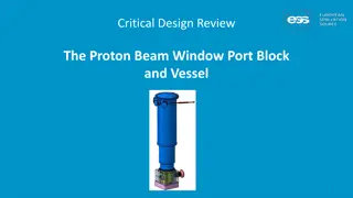
TEAM SEVEN CRITICAL DESIGN REVIEW.
During the critical design review, Team Seven presented their project purpose, objectives, and key elements related to developing an energy-efficient unmanned aerial system (UAS). The project aims to improve mission endurance, reduce user workload, and enhance communications in remote areas. By focusing on subsystems such as mission management, flight controls, hardware development, and flight trajectory optimization, the team is working towards a tailored solution to meet project requirements and address critical risks.
Download Presentation

Please find below an Image/Link to download the presentation.
The content on the website is provided AS IS for your information and personal use only. It may not be sold, licensed, or shared on other websites without obtaining consent from the author. Download presentation by click this link. If you encounter any issues during the download, it is possible that the publisher has removed the file from their server.
E N D
Presentation Transcript
TEAM SEVEN CRITICAL DESIGN REVIEW 1 Advisors Professor Mah Professor Rafi Hunter Ray TEAM SEVEN Sponsor Mr. John Mah Ty Banach, Maklen Estrada, Max Gerber, Sam Hatton, Alex Hubben, Collin Hudson, Mike Miller, Kevin Pipich, Bennett Spengler, Ethan Temby, Alessandro Villain, Jacob Wilson
AGENDA 03 01 02 Critical Project Elements and Risks Project Purpose Design Solution 04 05 06 Design Requirements and Their Satisfaction Verification and Validation Project Planning Design Solution Design Requirements Project Purpose Critical Elements and Risk Project Planning Verification and Validation
PROJECT OVERVIEW Problem TEAM SEVEN Objectives Program (HERD-CU) o Establish communications in remote areas Develop energy management solution based on mission trajectory o Lack of low-cost, energy efficient unmanned ariel systems (UAS) o Improve mission endurance o Reduce user workload by providing an optimized flight path o Limited emergency personnel Project (TEAM SEVEN) Enable trajectory solution via attitude control o COTS autopilot/ground station software not tailored for long endurance missions o Upgrade the native autopilot to fly a control architecture more optimal for this type of mission 4 Project Purpose Design Requirements Design Solution Verification and Validation Project Planning Critical Elements and Risk
5 Project Purpose Design Requirements Design Solution Verification and Validation Project Planning Critical Elements and Risk
SUBSYSTEMS & MAJOR PROJECT ELEMENTS Mission Management Flight Controls Hardware Flight Trajectory Based on Energy State Flight Hardware and Communications Development of Stability Augmentation System Simulink/MAVLINK/ROS 2 On-Board Computer Airframe Phoenix 2400 o o o Ground Station ROS 2 Integration with PX4 o 2nd Level Controls using LQR Pixhawk Flight Controller Battery/ESC/Servos/Wires o o o Custom Algorithms Transmitter/Receiver o o o Motor/Propellor o 7 Design Solution Project Purpose Design Requirements Project Planning Critical Elements and Risk Verification and Validation
HIGH LEVEL SYSTEMS ARCHITECTURE 8 Design Solution Project Purpose Design Requirements Project Planning Critical Elements and Risk Verification and Validation
MISSION MANAGEMENT P.F.D. 9 Design Solution Project Purpose Design Requirements Project Planning Critical Elements and Risk Verification and Validation
FLIGHT CONTROLS DIAGRAM Setpoint (attitude and thrust) Waypoint (position and velocity) 10 Design Solution Project Purpose Design Requirements Project Planning Critical Elements and Risk Verification and Validation
HARDWARE FBD 11 Design Solution Project Purpose Design Requirements Project Planning Critical Elements and Risk Verification and Validation
COMMUNICATION LINKS 12 Design Solution Project Purpose Design Requirements Project Planning Critical Elements and Risk Verification and Validation
AIRFRAME SENSOR SUITE 13 Design Solution Project Purpose Design Requirements Project Planning Critical Elements and Risk Verification and Validation
POWER MANAGEMENT 14 Design Solution Project Purpose Design Requirements Project Planning Critical Elements and Risk Verification and Validation
*Functional Requirements are in backup slides CRITICAL PROJECT ELEMENTS Energy Management Stability Augmentation System Flight Wind Boundaries Measurements FR 2 FR 3 FR 6 FR 3 FR 4 FR 6 FR 1 FR 4 FR 5 FR 1 FR 3 FR 5 o Primary goal of the mission o Necessary for implementing flight trajectory o Necessary safety consideration Measuring wind is complex o o Considered in each subsystem o Preserve LOS, ensure safe flight by not crashing Optimization is wind dependent o o Simplifies user input and improves safety Critical to success of mission o 16 Critical Elements and Risk Design Requirements Project Planning Design Solution Verification and Validation Project Purpose
RISK SUMMARY Risk 1 Risk 2 Risk 3 Predominant Wind Estimation Flight Condition Execution ROS2 Control Law Implementation o If ROS2 control laws cannot be implemented interfaced with existing PX4 code, o Then there will be significant design rework involved in restructuring PX4 code. o If the waypoints commanded by mission management includes added parameters, o Then flight control laws will have to be developed to meet these additional constraints. o If reliable wind estimates cannot be obtained, o Then flight condition optimization may result in limited improvement in terms of energy consumption. 17 Critical Elements and Risk Design Requirements Project Planning Design Solution Verification and Validation Project Purpose
RISK SCORING Probability: 2 Cost: 1 Technical: 3 Schedule: 1 Total: 6 R1: ROS2 Control Law Implementation 4 8 12 16 R2 Impact 3 6 9 12 Probability: 2 Cost: 1 Technical: 4 Schedule: 3 Total: 8 R2: Flight Condition Execution R1 R3 2 4 6 8 1 2 3 4 Probability: 3 Cost: 1 Technical: 3 Schedule: 2 Total: 9 R3: Predominant Wind Estimation Probability *Overall impact score is determined by the maximum of cost/technical/schedule 18 Critical Elements and Risk Design Requirements Project Planning Design Solution Verification and Validation Project Purpose
DESIGN ASPECTS: OUTER LOOP Purpose oLive path optimization o Update path characteristics while in flight o Desired velocity and shape o Based on wind speed and direction 20 Design Requirements Verification and Validation Project Planning Design Solution Project Purpose Critical Elements and Risk
KEY DESIGN REQUIREMENTS: OUTER LOOP Design Requirement 1.6 2.1 2.2 2.3 6.1 Ground station capable of transmitting flight plan to UAS Utilize Utilized existing off- the-shelf and natively developed software 20% increase in endurance compared to baseline flight profile Generate set of waypoints for a given UAS mission downlinked telemetry to develop optimized flight plan Description 21 Design Requirements Verification and Validation Project Planning Design Solution Project Purpose Critical Elements and Risk
TEMPEST POWER & ENERGY MODEL AIRCRAFT PERFORMANCE: GENERAL DR 2.1 22 Design Requirements Verification and Validation Project Planning Design Solution Project Purpose Critical Elements and Risk
TEMPEST POWER & ENERGY MODEL AIRCRAFT PERFORMANCE: POWER CURVES DR 2.1 (from drag polar) propeller efficiency + 20% endurance Assumptions: Baseline flight: SLUF @ 50% throttle 15 pitch propeller (typical efficiency curve) 23 Design Requirements Verification and Validation Project Planning Design Solution Project Purpose Critical Elements and Risk
TEMPEST POWER & ENERGY MODEL AIRCRAFT PERFORMANCE: WIND DR 2.1 24 Design Requirements Verification and Validation Project Planning Design Solution Project Purpose Critical Elements and Risk
PX4 MAVLINK PROTOCOL CONSTRAINT DR 1.6 DR 6.1 25 Design Requirements Verification and Validation Project Planning Design Solution Project Purpose Critical Elements and Risk
OPTIMIZATION DESIGN CHOICE WIND TRIANGLE AND GROUND SPEED DR 2.2 Goal: Command ground speed such that airspeed is constant Full derivation in backup slides 26 Design Requirements Verification and Validation Project Planning Design Solution Project Purpose Critical Elements and Risk
PATH MODELING MAXIMIZE TURN RADIUS 27 Design Requirements Verification and Validation Project Planning Design Solution Project Purpose Critical Elements and Risk
PATH MODELING FLYING PARALLEL TO THE WIND Flying parallel to the wind decreases risk: Lower control surface demand Lower flight controller uncertainty Lower impact from wind changes f Goal: Avoid side-slip and crab flight! 28 Design Requirements Verification and Validation Project Planning Design Solution Project Purpose Critical Elements and Risk
PATH MODELING FLYING PARALLEL TO THE WIND 29 Design Requirements Verification and Validation Project Planning Design Solution Project Purpose Critical Elements and Risk
OPTIMIZATION DESIGN CHOICE WIND TRIANGLE FLIGHT & PATH MODIFICATIONS DR 2.2 DR 2.3 DR 6.1 30 Design Requirements Verification and Validation Project Planning Design Solution Project Purpose Critical Elements and Risk
DESIGN ASPECTS: INNER LOOP Purpose oEfficient execution of waypoint path o Generate attitude setpoints throughout flight o Replace existing PX4 loops o ROS2 compatibility with PX4 Setpoint (attitude and thrust) Waypoint (position and velocity) 31 Design Requirements Verification and Validation Project Planning Design Solution Project Purpose Critical Elements and Risk
KEY DESIGN REQUIREMENTS: INNER LOOP Design Requirement 2.1 3.1 5.3 6.1 Autonomous flight for all phases of flight except launch and landing. Utilize existing off-the-shelf and natively developed software 20% increase in endurance compared to baseline flight profile Follow a set of predefined waypoints. Description 32 Design Requirements Verification and Validation Project Planning Design Solution Project Purpose Critical Elements and Risk
CONTROL ARCHITECTURE MODEL Goal Assumptions o The state of the aircraft experiencing a disturbance from SLUF can be modelled by a 2nd order approximation of aircraft modes. o To inform our control architecture trade, and evaluate what we can control o The aircraft state is characterized by the inertial velocity vector in the body x direction uE, and the pitch angle theta. 2nd Order Phugoid Approximation 33 Design Requirements Verification and Validation Project Planning Design Solution Project Purpose Critical Elements and Risk
CONTROL ARCHITECTURE MODEL 34 Design Requirements Verification and Validation Project Planning Design Solution Project Purpose Critical Elements and Risk
CONTROL ARCHITECTURE MODEL Outcomes o Model and architecture trade reduced design space, with Linear-Quadratic Regulator (LQR) being our chosen architecture. o Successfully controlled changes in state and rejected disturbances using LQR o Better suited for setpoint control 35 Design Requirements Verification and Validation Project Planning Design Solution Project Purpose Critical Elements and Risk
PX4 POSITION CONTROLLER Fixed Wing Position Controller o Position commands to attitude and thrust commands using PID o Calculates KE and PE of aircraft and attempts to remain at a specific energy level (KE + PE) Attitude Controller o Attitude and thrust to control surface deflection commands o Handles turn coordination and mode damping 36 Design Requirements Verification and Validation Project Planning Design Solution Project Purpose Critical Elements and Risk
INNER LOOP: DESIGN CHOICE Replace Position Controller o Replace TECS control architecture with LQR controller o TECS controls for unwanted factors, wasting energy o LQR can optimize for model converting waypoints to setpoints o More impactful energy savings o LQR controller implemented on ROS2 onboard computer 37 Design Requirements Verification and Validation Project Planning Design Solution Project Purpose Critical Elements and Risk
39 PX4 WIND ESTIMATION CHARACTERIZATION TEST Design Validation/CPE Pass/Fail Criteria Test Objective o Validation of method to use wind to fly at Pr,min and align path with wind direction o Estimate North-East wind velocity from PX4 o Pass: Error between PX4 wind speed measurements and GFS wind speed is within +/- 2 m/s & within +/- 22.5 o Validate PX4 wind measurements against NOAA GFS (Global Forecast System) wind data o Testing CPE 4 (Wind Measurements) o Fail: Error tolerances not met Verification and Validation Project Planning Design Solution Design Requirements Project Purpose Critical Elements and Risk
40 PX4 WIND ESTIMATION 40 Verification and Validation Project Planning Design Solution Design Requirements Project Purpose Critical Elements and Risk
PX4 WIND ESTIMATION MEASUREMENTS AND KEY ISSUES Key Issues Measurements o PX4 estimates the state of the aircraft using Extended Kalman Filtering (EKF) o Loss of Data o Sensor unable to return data o Large State Prediction Discrepancy o Velocity is used to determine Equivalent Airspeed (EAS) o Could cause EKF to attempt a reset of the states with the sensor observations o EAS data used to estimate North- East Wind Velocity 41 Verification and Validation Project Planning Design Solution Design Requirements Project Purpose Critical Elements and Risk
PX4 WIND ESTIMATION TEST READINESS Test Readiness o IMU (Inertial Measurement Unit) o Measures angular (rotation) rates and acceleration in aircraft body axis o Pitot Tube o Measures differential pressure to determine true airspeed o GPS (Global Positioning System) o Measures position (latitude, longitude, altitude) [deg, deg, meters] o Ground Station Logging o Saves flight logs to CSV on ground station computer 42 Verification and Validation Project Planning Design Solution Design Requirements Project Purpose Critical Elements and Risk
TEST READINESS -- PHOENIX 2400 2.4 M Wingspan ABS Plastic Hull 4023-1050kV Brushless Motor Readily Available Legacy Free for us 43 43 Verification and Validation Project Planning Design Solution Design Requirements Project Purpose Critical Elements and Risk
44 PHOENIX 2400 POWER CURVE CHARACTERIZATION TEST Design Validation/CPE Pass/Fail Criteria Test Objective o Pass: Power curve has an ?2 0.85 to a nonlinear fit curve o Use ideal airspeed to reduce power in flight to extend endurance o Determine power curve and minimum power required airspeed o Fail: Error exceeds an ?2 of 0.85 o Testing CPE 1 (Energy Management) o Verify power curve model (no drag polar available for the Phoenix 2400) Verification and Validation Project Planning Design Solution Design Requirements Project Purpose Critical Elements and Risk
PHOENIX 2400 POWER CURVE ESTIMATION PROCESS 45 45 Verification and Validation Project Planning Design Solution Design Requirements Project Purpose Critical Elements and Risk
PHOENIX 2400 POWER CURVE ESTIMATION MEASUREMENTS AND KEY ISSUES Key Issues Measurements oPX4 Telemetry oTrue airspeed oBattery voltage oBattery current draw oWind gusts or sudden changes in wind direction may yield unwanted test results oIdeally testing on calm day 46 Verification and Validation Project Planning Design Solution Design Requirements Project Purpose Critical Elements and Risk
PHEONIX 2400 POWER CURVE ESTIMATION TEST READINESS Test Readiness o PDB (Power Distribution Board) o Measures voltage and current draw from the battery o Most power will be used by the ESC/motor o Pitot Tube o Measures differential pressure to determine true airspeed o Ground Station Logging o Saves flight logs to CSV on ground station computer 47 Verification and Validation Project Planning Design Solution Design Requirements Project Purpose Critical Elements and Risk
PX4 WIND ESTIMATION AND PHOENIX POWER CURVE SAFETY RISKS Environmental Safety Unpredictable Winds o While taking measurements in flight, strong wind gust are possible o May compromise flight safety and lead to a crash o Battery ejection could cause fires in environment near test flight location Safety Risk Mitigation Plans Safety Risk Mitigation Plans o Fly at lower altitude to closely monitor flight status (< 6500ft MSL) o Avoid flying in extremely turbulent weather on test day o Fly in areas with steady winds o Develop protective housing for battery o Confirm with advisor and other faculty members the safety of the power management systems prior to flight 48 Verification and Validation Project Planning Design Solution Design Requirements Project Purpose Critical Elements and Risk
49 SIMULATION CHARACTERIZATION TEST Design Validation/CPE Pass/Fail Criteria Test Objective o Validating: o Messaging reliability o Guidance level loop fidelity o Pass: Aircraft reaches all waypoints within a 20-meter range o Send attitude setpoints and pre- defined waypoints to PX4 o Fail: Aircraft does not reach all waypoints and/or does not come within 20- meter range o Verify if aircraft reaches pre-defined waypoints within a selected range o Testing CPE 2 (Stability Augmentation System) Verification and Validation Project Planning Design Solution Design Requirements Project Purpose Critical Elements and Risk
50 SIMULATION TEST SET UP Output Input MAVLink 50 Verification and Validation Project Planning Design Solution Design Requirements Project Purpose Critical Elements and Risk
